EP0159948B1 - Kupplungsvorrichtung für, insbesondere landwirtschaftliche Geräte, getragen durch einen Traktor - Google Patents
Kupplungsvorrichtung für, insbesondere landwirtschaftliche Geräte, getragen durch einen Traktor Download PDFInfo
- Publication number
- EP0159948B1 EP0159948B1 EP19850400752 EP85400752A EP0159948B1 EP 0159948 B1 EP0159948 B1 EP 0159948B1 EP 19850400752 EP19850400752 EP 19850400752 EP 85400752 A EP85400752 A EP 85400752A EP 0159948 B1 EP0159948 B1 EP 0159948B1
- Authority
- EP
- European Patent Office
- Prior art keywords
- implement
- tractor
- points
- tool
- hitching
- Prior art date
- Legal status (The legal status is an assumption and is not a legal conclusion. Google has not performed a legal analysis and makes no representation as to the accuracy of the status listed.)
- Expired
Links
Images


Classifications
-
- A—HUMAN NECESSITIES
- A01—AGRICULTURE; FORESTRY; ANIMAL HUSBANDRY; HUNTING; TRAPPING; FISHING
- A01B—SOIL WORKING IN AGRICULTURE OR FORESTRY; PARTS, DETAILS, OR ACCESSORIES OF AGRICULTURAL MACHINES OR IMPLEMENTS, IN GENERAL
- A01B63/00—Lifting or adjusting devices or arrangements for agricultural machines or implements
- A01B63/02—Lifting or adjusting devices or arrangements for agricultural machines or implements for implements mounted on tractors
- A01B63/10—Lifting or adjusting devices or arrangements for agricultural machines or implements for implements mounted on tractors operated by hydraulic or pneumatic means
- A01B63/111—Lifting or adjusting devices or arrangements for agricultural machines or implements for implements mounted on tractors operated by hydraulic or pneumatic means regulating working depth of implements
- A01B63/114—Lifting or adjusting devices or arrangements for agricultural machines or implements for implements mounted on tractors operated by hydraulic or pneumatic means regulating working depth of implements to achieve a constant working depth
-
- A—HUMAN NECESSITIES
- A01—AGRICULTURE; FORESTRY; ANIMAL HUSBANDRY; HUNTING; TRAPPING; FISHING
- A01B—SOIL WORKING IN AGRICULTURE OR FORESTRY; PARTS, DETAILS, OR ACCESSORIES OF AGRICULTURAL MACHINES OR IMPLEMENTS, IN GENERAL
- A01B59/00—Devices specially adapted for connection between animals or tractors and agricultural machines or implements
- A01B59/04—Devices specially adapted for connection between animals or tractors and agricultural machines or implements for machines pulled or pushed by a tractor
- A01B59/042—Devices specially adapted for connection between animals or tractors and agricultural machines or implements for machines pulled or pushed by a tractor having pulling means arranged on the rear part of the tractor
-
- A—HUMAN NECESSITIES
- A01—AGRICULTURE; FORESTRY; ANIMAL HUSBANDRY; HUNTING; TRAPPING; FISHING
- A01B—SOIL WORKING IN AGRICULTURE OR FORESTRY; PARTS, DETAILS, OR ACCESSORIES OF AGRICULTURAL MACHINES OR IMPLEMENTS, IN GENERAL
- A01B59/00—Devices specially adapted for connection between animals or tractors and agricultural machines or implements
- A01B59/06—Devices specially adapted for connection between animals or tractors and agricultural machines or implements for machines mounted on tractors
- A01B59/066—Devices specially adapted for connection between animals or tractors and agricultural machines or implements for machines mounted on tractors of the type comprising at least two lower arms and one upper arm generally arranged in a triangle, e.g. three-point hitches
- A01B59/068—Devices specially adapted for connection between animals or tractors and agricultural machines or implements for machines mounted on tractors of the type comprising at least two lower arms and one upper arm generally arranged in a triangle, e.g. three-point hitches the lower arms being lifted or lowered by power actuator means provided externally on the tractor
Definitions
- the invention relates to a coupling device for a tool, in particular an agricultural tool, intended to be carried by a tractor, said tool being provided with means for hooking to a lifting system, of the three-point type, of the tractor, comprising an intermediate support provided between the tractor lifting system and the attachment means of the implement, this intermediate support comprising, in the upper part, an attachment point intended to be connected to the high point of the attachment means and , in the lower part, attachment means located towards its transverse ends and intended to be connected to the bottom attachment points of the tool.
- a coupling device of this kind is known, in particular from US-A-2 888 997.
- the coupling device shown in this document comprises an intermediate support fixed to the lifting system of the tractor, while the implement is connected to this intermediate support, both in the upper part and in the lower part, by articulated links.
- Significant play is provided at the articulation of each lower link to allow relative tilting movements, in particular on one side or the other, of the intermediate support and of the tool.
- the latter is therefore mounted in a sort of "floating" and if an area of this tool encounters harder ground than that encountered by the other end of the tool, the latter rocks so that the part attacking the harder ground rises, while the other end sinks into the softer soil. This results in balancing of the drag force on the tractor and reduces the lateral component of the drag.
- the quality of the working of the soil by the tool is not optimal since the work is not carried out at a practically constant depth over the entire surface of the soil.
- the speed and precision with which the tool movements are carried out need to be improved.
- Such a device cannot function correctly if it is placed at the front of the tractor, so as to be pushed, taking account of the unstable equilibria in the pushed position.
- a virtual theoretical axis linked to the spontaneous search for a stable equilibrium will not exist in thrust. There will be blockage in a given position.
- a device is also known according to FR-A-1 284 856 intended to allow wide implements to better follow the profile of the ground, independently of the tractor.
- this device does not allow good control of the stability of the tool in the raised position, which is annoying.
- the distribution of loads on the tool, as well as the speed and precision with which the movements of the tool are carried out need to be improved.
- GB-A-1 422 134 shows a hooking device involving a special plate, and not allowing direct hooking to the three-point device of a tractor.
- the object of the invention is, above all, to make coupling devices of the kind defined above such that they respond better than hitherto to the various requirements of practice and in particular such that they no longer have, or to a lesser degree, the drawbacks mentioned above.
- a coupling device for a tool in particular agricultural, of the kind defined above, is characterized in that, on the one hand, the intermediate support is rigid and comprises, in the upper part, two points of hooking located at the transverse ends and connected, respectively, by two connecting means extendable at the highest point of the lifting system of the tractor, these connecting means being suitable for transmitting the forces for lifting the implement carried by the tractor, the attachment point for the tool forming a third point located halfway between the end points, that on the other hand, in the lower part, the two attachment points are made in a manner similar to the attachment points conventional tractor so that the lower attachment points of the tool can be received in these attachment points, and that on the other hand finally, said support comprises, in the middle of its lower part, a means of articulation with geometric axis longitudi nal suitable for cooperating with a complementary articulation means secured to a transversely supported transverse bar about its geometric axis by the two low attachment points of the lifting system of the tractor, this articulation means being the only
- connection means comprise means for controlling the movements of the tool independently of the lifting system, these control means being combined with means sensitive to the position of the tool by report to the ground so that the information provided by these sensitive means is used for the actuation of the above control means.
- control means makes it possible to manage a load transfer from the tool to the tractor, on the basis of information from sensors on the position of the tool relative to the ground.
- connection means are formed by telescopic rods which, in the raised position of the lifting system, take their maximum length and come to a limit stop, the tool then being fitted with gauge wheels.
- the articulation means with a longitudinal geometric axis comprises a longitudinal articulation axis
- the complementary articulation means comprises a bore provided in a cylinder integral with the transverse bar
- the longitudinal articulation axis is located below the transverse bar.
- the above means sensitive to the position of the tool with respect to the ground may comprise, for each gauge wheel, a force sensor capable of determining the loads carried by the wheel, the information provided by each sensor serving to actuate the control means.
- control means are adapted to intervene so that the load supported by each gauge wheel remains substantially constant and equal to a predetermined value, in particular adjustable, between a minimum threshold and a maximum threshold, the additional load being transferred towards the tractor.
- a predetermined value in particular adjustable, between a minimum threshold and a maximum threshold, the additional load being transferred towards the tractor.
- the load values adopted for each gauge wheel are equal.
- the control means may comprise at least two elementary control means capable of developing, each, a control force, intended to be transmitted to the tool, having a component in the longitudinal direction, or direction of advance of the tool , and a component in the transverse direction, at least two means sensitive to the position of the tool relative to the ground being provided and associated respectively with the elementary control means.
- the two elementary control means are advantageously formed by two jacks whose axes are concurrent, the end of these jacks located towards the competition point being connected to a high point of the three-point lifting system of the tractor, while the two other ends of these jacks are connected, respectively, to two difierent points, spaced from one another in the transverse direction, and offset in the longitudinal direction relative to the above high point, the above two different points being rigidly connected between them and, when the tool is coupled, being rigidly connected to this tool.
- the intermediate support forms a sort of frame, comprising in the upper part three hooking points rigidly connected together, the two extreme points in the transverse direction constituting the above two dittent points to which the connecting means are connected, while the third attachment point, generally located midway between the two extreme points, is connected, in particular by an articulated link or the like, to the top point of the attachment means of the tool.
- the support comprises, at its lower part, two other attachment points, on each side, for receiving the two lower attachment points of the tool, this lower part of the support being mounted, in its middle part, on the means articulation allowing tilting of the support in at least two non-parallel directions, in particular orthogonal, parallel or substantially parallel to the ground.
- the support is provided, in the middle of its lower part, with the articulation means with a longitudinal axis, intended to be substantially horizontal while the mean plane of the support is substantially vertical, suitable for cooperating with the complementary articulation means integral with the transverse bar intended to be supported by the two low points of attachment of the three-point lifting system of the tractor, this bar being itself rotatably mounted around its transverse axis.
- connection between the ends of the connection means situated towards their point of competition, with the high point of the three-point lifting system of the tractor comprises a secondary part, intended to be hung at this high point of the lifting system of the tractor, and comprising two yokes integral with one another and forming between them an angle corresponding to that of the connection means, said ends of the connection means being hooked on these yokes.
- Such a coupling device can be provided either at the rear of the tractor, for a tool located at the rear, or at the front of the tractor, in which case the tool is pushed by the tractor, or both at the front and rear of the tractor for a pushed implement and for another pulled implement.
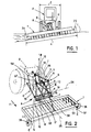
- Figure 1 of these drawings is an overall diagram of a tractor, equipped with a wide tool, pushed, seen from the front, to illustrate the movement of the tool relative to the tractor.
- FIG. 2 is a diagram, in perspective, of a coupling device according to the invention, mounted between the lifting system of the tractor and the attachment means of the tool.
- Figure 3 is a side view of the coupling device according to the invention.
- FIG. 4 is a top view with respect to FIG. 3.
- FIG. 5, finally, is a diagram illustrating an embodiment of the means sensitive to the load supported by a gauge wheel of the tool.
- FIGS. 1 and 2 one can see a coupling device A for a relatively wide agricultural or agricultural implement 1, intended to be carried by a tractor 2.
- the width L of the implement can be significantly greater than the width 1 of the tractor.
- the tool 1 is provided with means for hooking B to a lifting system C of the three-point type of the tractor 2.
- the coupling device comprises connection means R provided between the lifting system C of the tractor and the means of attachment B of the tool, these connection means R being arranged to allow movements of the tool allowing it to remain substantially parallel to the ground, at the level of the tool.
- the tool can take an inclination relative to the tractor, to follow the profile of the soil.
- connection means R comprise, between the attachment means B and the lifting system C, connection means J allowing the tool 1 to perform tilting movements around at least two axes 24, 25 not parallel to each other but parallel or substantially parallel to the ground T.
- connection means J comprise means of control S of the movements of the tool in an autonomous manner with respect to the lifting system C of the tractor, these control means S being combined with means E sensitive to the position of the tool 1 relative to the ground T, so that the information provided by these sensitive means E is used for the actuation of the above control means S.
- the lifting system C of the conventional tractor is of the three-point type, a high point 3 and two low points 4, 5.
- the high point 3 can be formed by a yoke provided at the end of an arm which can be raised or lowered in a longitudinal or vertical plane.
- Points 4 and 5 are provided at the ends of two longitudinal arms, articulated on the tractor.
- the attachment points 4 and 5 can be of the ball type.
- the attachment means B of the tool 1 comprise, for example, a rigid triangular frame 6 integral with the chassis of the tool 1.
- This frame 6 comprises a lower horizontal side, forming a base, the transverse ends of which 7, 6 could be hooked, in case the coupling device a according to the invention is not used, directly on points 4 and 5 of the lifting system of the tractor.
- the frame 6, the shape of which is that of an isosceles triangle, has its two equal sides which converge towards the apex 9 provided, for example, with a yoke. Still assuming that the coupling device A of the invention would not be used, this apex 9 would be directly connected by a bar or a rigid rod to the high point 3 of the lifting system of the tractor.
- connection means R comprise an intermediate support 10 also forming a sort of frame, this support comprising in the upper part three attachment points 11, 12, 13 rigidly connected to each other.
- the two points 11, 13 located at the transverse ends are connected to the aforementioned control means S while the third attachment point 12 located midway between the end points 11, 13 is connected by a rod 14, rigid, at the high point 9 attachment means B of the tool.
- the attachment points 11, 12 and 13 can be formed by yokes.
- the support 10 comprises, at its lower part, two other attachment points 15, 16 located at its transverse ends. These attachment points 15 and 16 are produced in a manner similar to the conventional attachment points 4 and 5 of the tractor so that the low attachment points 7 and 8 of the tool 1 can be received at these points attachment 15 and 16, without any adaptation necessary.
- the support 10 is provided, in the middle of its lower part, with a longitudinal hinge pin 17, that is to say parallel to the direction of advance P, shown diagrammatically by an arrow, of the tool 1.
- L axis 17 is perpendicular to the mean plane of the support 10, this mean plane being intended to be substantially vertical and transverse with respect to said direction of advance P.
- the support 10 is constructed so as to have great rigidity and can be formed by a triangulated structure as visible in FIG. 2. It comprises a horizontal upper rigid bar 18 whose attachment points 11, 12, and 13 are integral and a rigid lower horizontal bar 19, integral with the axis 17 and provided at its ends with attachment points 15 and 16. Diagonal bars respectively connect point 11 to point 15 and one end of axis 17 while two 20 other diagonal bars connect the point 13 to said end of the axis 17 and to the other attachment point 16.
- the four diagonal bars of the support 10 form a sort of capital M as visible in FIG. 2.
- the longitudinal axis 17 is received in a complementary articulation means formed by a bore 20 (fig. 3) provided in a cylinder 21 integral with a transverse bar 22 intended to hang on and to be supported by the two low points hooking 4 and 5 of the lifting system C of the tractor.
- the axis 17 is preferably located below the bar 22 allowing the passage of a PTO transmission over this axis 17 and between the triangulation of the tool and the connection means.
- the position of the axis 17 is chosen so as not to cause ground clearance problems during work.
- the cylinder 21 is located below the bar 22 and is fixed to this bar for example by gussets such as 23 in particular welded to said bar and to the cylinder.
- the bar 22 is mounted on the attachment points 4 and 5 so that it can rotate around the transverse geometric axis 24, relative to the lifting system C of the tractor.
- the support 10 can also rotate around the longitudinal geometric axis 25 of the cylinder 21 and the axis 17.
- the geometric axes 24 and 25, which are not parallel to each other, are parallel, or substantially parallel, to the ground T.
- the movements of the tool 1, in order to remain parallel to the ground, consist of tilting around these two axes.
- the control means S of the movements of the tool 1 comprise two elementary control means formed respectively by two jacks 26, 27 capable of developing, each, a control force such as F (FIG. 4), intended to be transmitted to the tool 1 and having a component FI in the longitudinal direction, or direction of advance P of the tool, pushed or pulled, and a component Ft in the transverse direction.
- F control force
- the axes of the two jacks 26, 27 are concurrent towards a geometric point 28 (FIG. 4) advantageously located in the center of the yoke constituting the top attachment point 3.
- the two jacks 26, 27 can be arranged so that the plane of their concurrent axes is horizontal when the tractor 2 and the tool 1 move on the same horizontal flat surface, but this characteristic is not essential.
- the two cylinders 26 and 27 could be inclined relative to the horizontal plane.
- each cylinder located towards the competition point 28, is connected to the high point 3 of the lifting system C.
- Each end is equipped with a ball joint suitable for being received between the branches of two respective female yokes 31, 32, integral with one another and forming between them an angle corresponding to that of the jacks.
- the yokes 31, 32 are part of a secondary part 33 which has a male yoke 38 suitable for being received in a female yoke constituting the attachment point 3.
- the connection between the various male and female yokes is ensured by transverse axes such as 34, orthogonal to the forces transmitted between the yokes.
- the jacks 26 and 27 when the tractor and the implement are rolling on a flat horizontal surface are symmetrical to each other with respect to a longitudinal vertical plane passing through the point 28.
- the attachment points 11 and 13 are also symmetrical with respect to this longitudinal plane, and are produced in the form of yokes, as visible in FIG. 4, secured, in particular by welding, to the support 10, and oriented in the inclined direction of the associated jack.
- the rods 26a, 27a of the jacks 26, 27 are provided at their ends with ball joints attached to points 11 and 13.
- the tool 1 has two gauge wheels 35, 36 ( Figure 2) provided on each side of the tool, in the transverse direction. If tool 1 was located at the rear of the tractor and pulled by it, the gauge wheels 35 and 36 would be at the rear of tool 1. In the envisaged case of a tool pushed by the tractor and mounted at the front of this tractor, the gauge wheels are located in front of said tool. Part of the load on tool 1, due to the weight and dynamic effects, is exerted on these gauge wheels 35, 36.
- gauge wheels 35, 36 mounted at the end of a longitudinal arm 37, substantially parallel to the direction P, this arm being articulated around a transverse axis 37a schematically represented.
- the wheel 35, 36 can be mounted at the lower end of a vertical rod 37b fixed, in particular in an adjustable manner in the vertical direction, at the end of the arm 37 remote from the axis 37a.
- Elastic means formed by a block 37c of elastic material, for example elastomer, are provided between the arm 37 and a stop 37d secured to the frame of the tool 1 to allow the movement of the arm 37 while limiting it.
- Block 37c in the example considered works in compression.
- the position of this block 37c is advantageously adjustable in the longitudinal direction shown by the double arrow F in FIG. 5. The adjustment of the position of the block 37c makes it possible to adjust the load supported by the wheel 35.
- the means E (see FIGS. 2 and 5) sensitive to the position of the tool 1 relative to the ground T, are advantageously constituted by the gauge wheel 35, 36 comprising a force sensor capable of determining the supported loads by the associated wheel, the information provided by each sensor used to actuate the control means S.
- the force sensor 39 for the wheel 35 (or 40 for the wheel 36) comprises a cam 41 linked in rotation to the arm 37 supporting the wheel and an electrical contact 42 comprising a feeler 43 which presses against the cam 41.
- the probe 43 is pushed against the cam 41 by a spring 44 housed in a housing 45 linked to the chassis of the tool 1; the spring 44 bears at one end against a stop 46.
- the contact 42 in the rest position the contact 42 is open; the electrical contact can be established between the pad 47, (formed for example of two elementary pads spaced from one another carried by the probe 43) and the pads 48a, 48b linked to the housing 45; these tablets are suitably insulated,;:, ... compared to neighboring rooms.
- the contact between the pads 47, 48a closes when the load supported by the wheel 35 exceeds the predetermined limit, because the rotation of the cam 41, clockwise according to the representation of FIG. 5, causes the displacement of the rod 43 to the right of the drawing in FIG. 5 until the contact is closed.
- the contact between the pads 47 and 48b closes when the load supported by the wheel 35 becomes too low, which causes movement of the probe 43 in the other direction.
- the three pads 47, 48a, 48b, of the electrical contact are connected by electrical connection conductors 49, 50a, 50b to two control assemblies 51a, 51b for example electromagnets, acting on a distributor 52 of hydraulic fluid under pressure, intended to control the supply of the jack 26 associated with the wheel 35.
- the hydraulic fluid under pressure comes from a source 53 connected by suitable pipes 54 to orifices of the distributor 52.
- the cylinder 26 can be of the single-acting type and a single chamber of this cylinder is connected by a pipe 55 to an orifice of the solenoid valve 52.
- the cylinder 26 works to shorten, that is to say that when the liquid under pressure is admitted into the cylinder chamber, the rod 26a of the latter enters the cylinder.
- the return of the jack, when the pipe 55 is connected to the cover, is provided by the load against which the jack is intended to act, this load causing the rod 26a to exit.
- the assembly is arranged so that when the electrical contacts are open, the solenoid valve 52 is in a closed position and the hydraulic fluid is trapped in the cylinder chamber 26 so that the piston and the piston rod of this cylinder cannot move in translation relative to the cylinder of the cylinder, under the effect of the load.
- control means S make it possible for each gauge wheel 35, 36 to bear a substantially constant load.
- control means S are adjusted so that the load supported by the wheel 35 is equal to that supported by the wheel 36.
- force sensors than that shown in FIG. 5 can be used.
- force sensors such as 39, 40 it is possible to detect variations in load on the gauge wheels to which correspond variations in height of the tool relative to the ground T, relatively small, for example of the order of a centimeter or even of the order of a few millimeters.
- the force sensors such as 39, 40 make it possible to accurately detect the load transferred to the tractor without altering the position relative to the ground.
- the attachment point 3 is put in place of the lifting system C of the tractor, the intermediate piece 33 comprising the yokes 31, 32.
- the bar 22 is then put in place by hooking it to the two low points 4, 5 of the lifting system C of the tractor.
- the ends 29, 30 of the rods secured to the cylinders 26, 27 are hooked to the yokes 31, 32, using pins such as 34.
- the support 10 is then put in place by inserting the pin 17 into the bore 20 supported by bar 22 and by attaching points 11 and 13 of this support 10 to the 25 rods 26a, 27a, jacks 26 and 27.
- the axis 17 can be blocked, removably, in the longitudinal direction, relative to the bore 20; the support 10 and the bar 22 then form an assembly.
- the tool is then fixed, by its frame 6, to the support 10, the three points 7, 8 and 9 of this frame 6 being attached to points 15, 16 and 12 of said support 10.
- the operation of the coupling device is as follows.
- the moment of the transverse component Ft relative to the axis 25 causes, according to the representation of FIG. 2, a rotation of the support 10 and therefore a tilting of the tool 1, around this axis 25, in the opposite direction of the clockwise, seen from the rear of the tool 1, so that the load supported by the wheel 35 decreases.
- the device according to the invention makes it possible to positively control the maintenance of the tool 1 parallel to the ground by ensuring substantially constant loads on the gauge wheels 35, 36, these loads being preferably equal.
- the coupling device and its control can be adapted according to the nature of the soil worked by the tool. For example, for a hard floor, the setting of the spring 44 will correspond to a higher value and therefore to a higher load on the wheel 35, which makes it possible to smooth the information collected by the sensors and to eliminate instantaneous variations such as those caused by hard earthy notes, linked to the state of the surface. The load supported by the tractor is then lower, but this is not a problem since the tractor has good grip, because the ground is hard.
- the sensors 39 and 40 are adjusted so that the load supported by the wheels 35 and 36 is relatively low to increase the grip of the tractor, the problem of smoothing the information provided by the sensors being less acute.
- stops such as 56, 57 (FIGS. 3 and 4) suitable for coming to cooperate with the transverse bar 25, at during rotation about the longitudinal axis 25, to limit the amplitude of this rotation.
- the yoke constituting the point of attachment 12 of the support 10, and to which the connecting rod 14 is hung may have, in its wings, several holes 58, superimposed, three for example in the case of the figure 3, which allows the attachment of said rod 14 to the pair of holes best suited for the tool in question.
- a spherical ball joint located on the bar 19 equidistant from points 15 and 16, and suitable for cooperating with an additional housing carried by a support mounted on the attachment points 4 and 5 of the tractor.
- the support 10 would have freedom in rotation around a plurality of axes parallel to the ground.
- the example described above relates to a tool of the pushed type which tends to sink when the resistance of the soil increases.
- the single acting cylinder while working to shorten, opposes this tendency to sink.
- connection means J comprise control means S, in particular formed by jacks, tilting movements of the tool.
- connection means J would be passive and formed, for example, by telescopic rods.
- the telescopic links would allow tilting movements around the two axes 24, 25, without ensuring load transfer to the tractor; in other words, points 11 and 13 would in some way be free to debate along the straight line passing through these points and point 28.
- the telescopic rods In the raised position of the lifting system C of the tractor, the telescopic rods would take their maximum length and come into abutment stroke to ensure the transmission of forces for lifting the implement carried by the tractor.
Landscapes
- Life Sciences & Earth Sciences (AREA)
- Engineering & Computer Science (AREA)
- Mechanical Engineering (AREA)
- Soil Sciences (AREA)
- Environmental Sciences (AREA)
- Zoology (AREA)
- Agricultural Machines (AREA)
Claims (13)
Applications Claiming Priority (2)
| Application Number | Priority Date | Filing Date | Title |
|---|---|---|---|
| FR8406046A FR2562752B1 (fr) | 1984-04-17 | 1984-04-17 | Dispositif d'attelage pour un outil, notamment agricole, destine a etre porte par un tracteur, elements de ce dispositif et ensemble comprenant un tel dispositif |
| FR8406046 | 1984-04-17 |
Publications (2)
| Publication Number | Publication Date |
|---|---|
| EP0159948A1 EP0159948A1 (de) | 1985-10-30 |
| EP0159948B1 true EP0159948B1 (de) | 1988-08-10 |
Family
ID=9303224
Family Applications (1)
| Application Number | Title | Priority Date | Filing Date |
|---|---|---|---|
| EP19850400752 Expired EP0159948B1 (de) | 1984-04-17 | 1985-04-16 | Kupplungsvorrichtung für, insbesondere landwirtschaftliche Geräte, getragen durch einen Traktor |
Country Status (3)
| Country | Link |
|---|---|
| EP (1) | EP0159948B1 (de) |
| DE (1) | DE3564173D1 (de) |
| FR (1) | FR2562752B1 (de) |
Families Citing this family (6)
| Publication number | Priority date | Publication date | Assignee | Title |
|---|---|---|---|---|
| DE3630873A1 (de) * | 1986-09-11 | 1988-03-17 | Fendt & Co Xaver | Geraeteanbauvorrichtung fuer landwirtschaftlich nutzbare zugfahrzeuge |
| FR2628284B1 (fr) * | 1988-03-08 | 1990-12-07 | Defrancq Hubert | Dispositif d'attelage pour un outil, en particulier un outil agricole, destine a etre porte par un tracteur |
| FR2649580B1 (fr) * | 1989-07-13 | 1992-02-07 | Defrancq Hubert | Systeme d'attelage et de relevage pour un outil, notamment agricole, propre a etre monte a l'avant d'un tracteur |
| FR2850525B1 (fr) * | 2003-01-31 | 2006-01-13 | Indust Design | Systeme d'accrochage d'outil pour vehicule de travaux et vehicule de travaux equipe d'un tel systeme d'accrochage |
| US9968030B2 (en) | 2010-06-22 | 2018-05-15 | Cnh Industrial Canada, Ltd. | Down pressure adjustment device and method for use with a disc opener assembly of an agricultural implement |
| CN111357417A (zh) * | 2020-05-07 | 2020-07-03 | 山西农业大学 | 一种丘陵山地拖拉机悬挂装置自适应机构 |
Family Cites Families (7)
| Publication number | Priority date | Publication date | Assignee | Title |
|---|---|---|---|---|
| US2888997A (en) * | 1956-11-30 | 1959-06-02 | Frank M Fraga | Compensating hitch |
| US3432184A (en) * | 1967-07-10 | 1969-03-11 | United States Steel Corp | Power actuated tractor hitch |
| CA930233A (en) * | 1968-12-10 | 1973-07-17 | Sweet Ralph | Automatic depth control device for tillage units |
| GB1422134A (en) * | 1972-09-20 | 1976-01-21 | Shelton P A | Three point linkage |
| US4031963A (en) * | 1975-04-14 | 1977-06-28 | Erhard Poggemiller | Depth control device for ground working agricultural implements |
| US4355688A (en) * | 1981-01-29 | 1982-10-26 | Deere & Company | Agricultural implement and depth control therefor |
| FR2531303B2 (fr) * | 1981-09-07 | 1986-09-12 | Naud Expl Charrues | Dispositif destine a ameliorer l'adherence au sol de tracteurs portant des outils de travail du sol |
-
1984
- 1984-04-17 FR FR8406046A patent/FR2562752B1/fr not_active Expired
-
1985
- 1985-04-16 DE DE8585400752T patent/DE3564173D1/de not_active Expired
- 1985-04-16 EP EP19850400752 patent/EP0159948B1/de not_active Expired
Also Published As
| Publication number | Publication date |
|---|---|
| FR2562752A1 (fr) | 1985-10-18 |
| DE3564173D1 (en) | 1988-09-15 |
| EP0159948A1 (de) | 1985-10-30 |
| FR2562752B1 (fr) | 1987-08-14 |
Similar Documents
| Publication | Publication Date | Title |
|---|---|---|
| FR2485322A1 (fr) | Dispositif de relevage et d'abaissement pour outil, instrument ou machine agricole | |
| FR2649580A1 (fr) | Systeme d'attelage et de relevage pour un outil, notamment agricole, propre a etre monte a l'avant d'un tracteur | |
| EP0159948B1 (de) | Kupplungsvorrichtung für, insbesondere landwirtschaftliche Geräte, getragen durch einen Traktor | |
| FR3023448A1 (fr) | Dispositif apte a se deplacer le long d'un rang de culture et integrant au moins un porte-outil flottant | |
| FR2756699A1 (fr) | Machine agricole de preparation de la terre a outils independants | |
| FR2562378A1 (fr) | Dispositif de regulation automatique de l'attitude d'un accessoire de machine agricole tel qu'une rampe de pulverisation | |
| EP2959759B1 (de) | Landwirtschaftliche maschine, die mit einer zentriervorrichtung ausgestattet ist | |
| EP3707983B1 (de) | Landwirtschaftliche maschine mit einer verteilenden zugstange | |
| FR2681563A1 (fr) | Dispositif stabilisateur pour vehicule agricole. | |
| EP1029432B1 (de) | Sämaschine | |
| FR2534110A1 (fr) | Dispositif destine a supporter, au moins partiellement, le poids d'une machine agricole | |
| FR2580893A1 (fr) | Appareil perfectionne pour la preparation des sols au moyen d'un rouleau sous le tracteur et dont la pression exercee au sol est reglable, avant ou pendant le travail. | |
| WO1997015177A1 (fr) | Charrue reversible portee a largeur variable avec dispositif de recentrage du bati sur l'axe de retournement | |
| FR2622386A2 (fr) | Machine agricole pour le travail du sol | |
| EP4460172B1 (de) | Vorrichtung und system zur schnittstelle zwischen einer landwirtschaftlichen traktorkupplung und einem arbeitsgerät | |
| EP3973756B1 (de) | Gezogene landwirtschaftliche erntemaschnie mit einer verstellbaren achsvorrichtung | |
| FR2701798A1 (fr) | Charrue multi-socs réversible semi-portée. | |
| EP1111986A1 (de) | Fahrwerk für landwirtschaftliche maschine | |
| FR2800972A1 (fr) | Dispositif de fauchage des vegetaux | |
| EP1021942B1 (de) | Landwirtschaftliche Egge | |
| FR2877539A1 (fr) | Engin agricole comportant un outil a correction de devers | |
| FR2598277A1 (fr) | Machine agricole pour le travail du sol | |
| EP1133429A1 (de) | Hebezeug am vorderseite einem raupenschlepper und damit ausgerüsteten rupenschlepper | |
| FR2967865A1 (fr) | Machine agricole a correction automatique d'assiette | |
| FR2725340A1 (fr) | Machine agricole trainee a semi-portee avec amortisseur |
Legal Events
| Date | Code | Title | Description |
|---|---|---|---|
| PUAI | Public reference made under article 153(3) epc to a published international application that has entered the european phase |
Free format text: ORIGINAL CODE: 0009012 |
|
| AK | Designated contracting states |
Designated state(s): DE GB |
|
| 17P | Request for examination filed |
Effective date: 19860226 |
|
| 17Q | First examination report despatched |
Effective date: 19861205 |
|
| D17Q | First examination report despatched (deleted) | ||
| GRAA | (expected) grant |
Free format text: ORIGINAL CODE: 0009210 |
|
| AK | Designated contracting states |
Kind code of ref document: B1 Designated state(s): DE GB |
|
| REF | Corresponds to: |
Ref document number: 3564173 Country of ref document: DE Date of ref document: 19880915 |
|
| GBT | Gb: translation of ep patent filed (gb section 77(6)(a)/1977) | ||
| PLBE | No opposition filed within time limit |
Free format text: ORIGINAL CODE: 0009261 |
|
| STAA | Information on the status of an ep patent application or granted ep patent |
Free format text: STATUS: NO OPPOSITION FILED WITHIN TIME LIMIT |
|
| 26N | No opposition filed | ||
| PGFP | Annual fee paid to national office [announced via postgrant information from national office to epo] |
Ref country code: GB Payment date: 19910408 Year of fee payment: 7 |
|
| PGFP | Annual fee paid to national office [announced via postgrant information from national office to epo] |
Ref country code: DE Payment date: 19910523 Year of fee payment: 7 |
|
| PG25 | Lapsed in a contracting state [announced via postgrant information from national office to epo] |
Ref country code: GB Effective date: 19920416 |
|
| GBPC | Gb: european patent ceased through non-payment of renewal fee | ||
| PG25 | Lapsed in a contracting state [announced via postgrant information from national office to epo] |
Ref country code: DE Effective date: 19930101 |