EP0161652B1 - Ringschraube - Google Patents
Ringschraube Download PDFInfo
- Publication number
- EP0161652B1 EP0161652B1 EP85105823A EP85105823A EP0161652B1 EP 0161652 B1 EP0161652 B1 EP 0161652B1 EP 85105823 A EP85105823 A EP 85105823A EP 85105823 A EP85105823 A EP 85105823A EP 0161652 B1 EP0161652 B1 EP 0161652B1
- Authority
- EP
- European Patent Office
- Prior art keywords
- threaded bolt
- ring
- screw
- annular plate
- ring element
- Prior art date
- Legal status (The legal status is an assumption and is not a legal conclusion. Google has not performed a legal analysis and makes no representation as to the accuracy of the status listed.)
- Expired
Links
- 239000004567 concrete Substances 0.000 claims abstract description 10
- 230000008878 coupling Effects 0.000 claims description 8
- 238000010168 coupling process Methods 0.000 claims description 8
- 238000005859 coupling reaction Methods 0.000 claims description 8
- 238000009434 installation Methods 0.000 claims 1
- 238000005452 bending Methods 0.000 description 3
- 239000011178 precast concrete Substances 0.000 description 2
- 230000000694 effects Effects 0.000 description 1
- 238000004519 manufacturing process Methods 0.000 description 1
- 239000007787 solid Substances 0.000 description 1
Images

Classifications
-
- B—PERFORMING OPERATIONS; TRANSPORTING
- B66—HOISTING; LIFTING; HAULING
- B66C—CRANES; LOAD-ENGAGING ELEMENTS OR DEVICES FOR CRANES, CAPSTANS, WINCHES, OR TACKLES
- B66C1/00—Load-engaging elements or devices attached to lifting or lowering gear of cranes or adapted for connection therewith for transmitting lifting forces to articles or groups of articles
- B66C1/10—Load-engaging elements or devices attached to lifting or lowering gear of cranes or adapted for connection therewith for transmitting lifting forces to articles or groups of articles by mechanical means
- B66C1/62—Load-engaging elements or devices attached to lifting or lowering gear of cranes or adapted for connection therewith for transmitting lifting forces to articles or groups of articles by mechanical means comprising article-engaging members of a shape complementary to that of the articles to be handled
- B66C1/66—Load-engaging elements or devices attached to lifting or lowering gear of cranes or adapted for connection therewith for transmitting lifting forces to articles or groups of articles by mechanical means comprising article-engaging members of a shape complementary to that of the articles to be handled for engaging holes, recesses, or abutments on articles specially provided for facilitating handling thereof
- B66C1/666—Load-engaging elements or devices attached to lifting or lowering gear of cranes or adapted for connection therewith for transmitting lifting forces to articles or groups of articles by mechanical means comprising article-engaging members of a shape complementary to that of the articles to be handled for engaging holes, recesses, or abutments on articles specially provided for facilitating handling thereof for connection to anchor inserts embedded in concrete structures
-
- F—MECHANICAL ENGINEERING; LIGHTING; HEATING; WEAPONS; BLASTING
- F16—ENGINEERING ELEMENTS AND UNITS; GENERAL MEASURES FOR PRODUCING AND MAINTAINING EFFECTIVE FUNCTIONING OF MACHINES OR INSTALLATIONS; THERMAL INSULATION IN GENERAL
- F16B—DEVICES FOR FASTENING OR SECURING CONSTRUCTIONAL ELEMENTS OR MACHINE PARTS TOGETHER, e.g. NAILS, BOLTS, CIRCLIPS, CLAMPS, CLIPS OR WEDGES; JOINTS OR JOINTING
- F16B35/00—Screw-bolts; Stay-bolts; Screw-threaded studs; Screws; Set screws
- F16B35/04—Screw-bolts; Stay-bolts; Screw-threaded studs; Screws; Set screws with specially-shaped head or shaft in order to fix the bolt on or in an object
- F16B35/06—Specially-shaped heads
-
- F—MECHANICAL ENGINEERING; LIGHTING; HEATING; WEAPONS; BLASTING
- F16—ENGINEERING ELEMENTS AND UNITS; GENERAL MEASURES FOR PRODUCING AND MAINTAINING EFFECTIVE FUNCTIONING OF MACHINES OR INSTALLATIONS; THERMAL INSULATION IN GENERAL
- F16B—DEVICES FOR FASTENING OR SECURING CONSTRUCTIONAL ELEMENTS OR MACHINE PARTS TOGETHER, e.g. NAILS, BOLTS, CIRCLIPS, CLAMPS, CLIPS OR WEDGES; JOINTS OR JOINTING
- F16B45/00—Hooks; Eyes
- F16B45/002—Eyes
Definitions
- the invention relates to an eyebolt for introducing large forces into a concrete part with a threaded bolt that is screwed into an internal thread anchored in the concrete part, with a ring element for introducing tensile forces that can be rotated relative to the threaded bolt and that surrounds the threaded bolt with an annular plate.
- a ring element for introducing tensile forces that can be rotated relative to the threaded bolt and that surrounds the threaded bolt with an annular plate.
- an outer holding member and an inner collar on the threaded bolt between which the ring part is rotatably arranged and with a support surface for the ring element which surrounds the threaded bolt.
- DE-A 1 500 642 describes an eyebolt of the type specified above.
- This eyebolt is used to screw into a concrete part, so that a load can be anchored to the concrete part.
- the aim is to achieve the most effective and safe load pick-up possible in order to prevent the connection from failing.
- Similar problems arise when it comes to transporting precast concrete parts and when a hoist has to be connected to an eyebolt screwed into a precast concrete part.
- the ring element adjusts itself to the direction of the force introduced in the case of inclined pulls.
- the rotatability of the ring part is provided around the threaded bolt, but also a pivotability between the ring element, to which a cable pull engages, for example, and an annular plate which can be rotated around the threaded bolt.
- the arrangement of a joint between the annular plate and the ring element, which runs parallel to the outer surface of the concrete part, increases the distance of the load application point from the support surface.
- the use of hinge pins also increases the effort and limits the smallest cross-sectional area that transmits the forces.
- the invention has for its object to further develop an eyebolt of the type specified in such a way that larger forces can be transmitted with the same external dimensions without increasing the manufacturing effort.
- the invention proposes that the annular plate surrounding the threaded bolt is formed in one piece with the ring element.
- the eyebolt according to the invention adjusts itself sufficiently to inclined pulls.
- the ring element rotates so easily that the cable pulling the ring element lies in the plane formed by the ring element.
- the eyebolt interacts optimally with the support surfaces provided, so that no bending moments occur which could stress the threaded bolt.
- the eyebolt loosens in the internal thread.
- the ring element may not twist. But even then, the support surfaces provided remain sufficiently effective and the forces and moments that occur remain manageable.
- the inner collar is designed as a support plate on which the annular plate is supported.
- the collar which resembles a support plate, is formed in one piece with the threaded bolt. This gives a compact design, which reduces the bending moments that occur.
- the ring element can be rotated relative to the threaded bolt, it is clear that the threaded bolt cannot simply be screwed in by means of the ring element.
- the screwability can be achieved, for example, in that the holding member or the outer end of the threaded bolt has a key surface.
- drivers can also be provided between the holding member and the ring element or the support plate connected to the ring element. Such drivers can have a different configuration.
- the coupling can be carried out by means of a coupling, one coupling element being arranged on the threaded bolt and the other coupling element being arranged on the intermediate member. In this way, the threaded bolt can be rotated by means of the intermediate member.
- the invention further proposes resilient drivers which disengage above a predetermined torque.
- the threaded bolt with the ring element can simply be screwed in, for example by means of the intermediate member. Once he has reached the correct position in the load, the ring element can be rotated and brought into a position that is required for the correct application of force.
- an actuatable driver is also possible, for example a pin which is inserted into the holding member or into the threaded bolt in such a way that a screwing-in movement is possible on the ring element.
- drivers which can be screwed in radially to the screw axis are provided are, which fully release the ring element with a sufficient screw-in depth, on the other hand, with partial screw-in, form a stop for the ring element, so that the screwing in succeeds.
- the invention proposes a symmetrical ring element which, parallel to the outer surface of the load, has substantially larger dimensions than perpendicular to this outer surface.
- a ring element of this design will adjust itself in the correct direction during an inclined pull, in which the load direction then runs in the plane of the ring of the ring element.
- the ring element 1 has substantially larger dimensions in the direction of the outer surface 13 of the load 14 than perpendicularly thereto, so that a corresponding alignment of the ring element 1 occurs when the intermediate member 12 is pulled.
- the intermediate member 12 can be a solid ring, for example, which can be suspended in a crane hook.
- the intermediate element 12 can also be a rope loop, for example in the form of an 8.
- the threaded bolt 3 is screwed into a sleeve 15 with an internal thread 16, which sleeve 15 is anchored in the load 14.
- a recess 17 is provided in the outer surface 13 of the load, which is able to receive the support plate 6, which is connected in one piece to the ring element.
- the threaded bolt 3 has a collar 5, which gives the ring element 1 an attachment.
- the ring element 1 or the support plate 6 are held in the desired position by means of the screwed-on holding member 4, the holding member being held at the desired distance from the collar 5 by a transverse bore 18 with a split pin or the like.
- a spring 19 is mounted, which presses a ball 8 into a recess on the outer surface of the support plate.
- the threaded bolt 3 can be screwed in by means of the ring element 1.
- the ring member 1 can be rotated over the ball 8, and rotated for example half a turn, so that without locking the ball 8 an alignment of the ring element according to the load is possible.
- the support plate 6 lies on the bottom of the recess 17 in order to safely introduce the forces.
- the threaded bolt 3 is connected in one piece to the support plate 6, while the ring element 2 rests with its annular plate 21 on the support plate 6 and is supported on the holding member 4.
- a coupling 9 is provided as a driver between the intermediate member 12 and the threaded bolt.
- a slot is arranged on the intermediate member 12, which serves as a coupling element 11 and interacts with a projecting strip 10 on the bolt 3.
- a recess is provided in the holding member 4, into which the pin-like driver 7 can be inserted.
- This pin 7 is captively connected to the ring element 2.
Landscapes
- Engineering & Computer Science (AREA)
- General Engineering & Computer Science (AREA)
- Mechanical Engineering (AREA)
- Connection Of Plates (AREA)
- Polishing Bodies And Polishing Tools (AREA)
- Load-Bearing And Curtain Walls (AREA)
- Forms Removed On Construction Sites Or Auxiliary Members Thereof (AREA)
- Load-Engaging Elements For Cranes (AREA)
Description
- Die Erfindung betrifft eine Ringschraube zum Einleiten großer Kräfte in ein Betonteil mit einem Gewindebolzen, der in ein im Betonteil verankertes Innengewinde eingeschraubt ist, mit einem Ringelement zur Einleitung von Zugkräften, das gegenüber dem Gewindebolzen verdrehbar ist und das mit eine ringförmigen Platte den Gewindebolzen umgibt, mit einem äußeren Halteglied und einem inneren Bund am Gewindebolzen, zwischen denen der Ringteil verdrehbar angeordnet ist und mit einer Abstützfläche für das Ringelement, das den Gewindebolzen umgibt.
- In der DE-A 1 500 642 ist eine Ringschraube der vorstehend angegebenen Gattung beschrieben. Diese Ringschraube dient zum Einschrauben in ein Betonteil, so daß an dem Betonteil eine Last verankert werden kann. Dabei geht es darum, eine möglichst effektive und sichere Lastaufnahme zu erreichen, um ein Versagen der Verbindung auszuschließen. Gleichartige Probleme treten auf, wenn es darum geht, Betonfertigteile zu transportieren und wenn ein Hebezeug mit einer in ein Betonfertigteil eingeschraubten Ringschraube zu verbinden ist. Um auszuschließen, daß auf die Ringschraube, und zwar insbesondere auf den Gewindebolzen bei Schrägzügen erhebliche zusätzliche Belastungen einwirken, ist es bekannt, eine ringförmige Abstützfläche vorzusehen, die den Gewindebolzen umgibt, so daß bei Schrägzügen kein Biegemoment auf den Gewindebolzen einwirken kann.
- Das Ringelement stellt sich bei der bekannten Ringschraube bei Schrägzügen auf die Richtung der eingeleiteten Kraft ein. Zu diesem Zweck ist die Verdrehbarkeit des Ringteils um den Gewindebolzen vorgesehen, aber auch eine Verschwenkbarkeit zwischen dem Ringelement, an dem beispielsweise ein Seilzug angreift und ringförmigen Platte, die um den Gewindebolzen verdrehbar ist. Die Anordnung eines Gelenkes zwischen ringförmigen Platte und dem Ringelement, das parallel zur Außenfläche des Betonteils verläuft, vergrößert den Abstand des Lastangriffspunktes von der Stützfläche. Die Verwendung von Gelenkbolzen vergrößert zudem den Aufwand und begrenzt die kleinste, die Kräfte übertragende Querschnittsfläche.
- Der Erfindung liegt die Aufgabe zugrunde, eine Ringschraube der eingangs angegebenen Gattung dahingehend weiter zu entwickeln, daß bei gleichen Außenabmessungen größere Kräfte übertragbar sind, ohne daß der Herstellungsaufwand vergrößert wird.
- Zur Lösung dieser Aufgabe wird ausgegangen von der Ringschraube der eingangs angegebenen Gattung. Die Erfindung schlägt vor, daß die den Gewindebolzen umgebende ringförmige Platte einstückig mit dem Ringelement ausgebildet ist.
- Bei der Erfindung ist somit nur eine Verdrehbarkeit des Ringelementes um den Gewindebolzen gegeben. Eine Neigbarkeit des Ringelementes um eme Achse rechtwinklig zur Achse des Gewindebolzens fehlt dagegen.
- Überraschenderweise wurde gefunden, daß sich die erfindungsgemäße Ringschraube ausreichend auf Schrägzüge einstellt. Bei Belastung verdreht sich das Ringelement ohne weiteres so, daß der Seilzug, der am Ringelement angreift, in der Ebene liegt, die durch das Ringelement gebildet wird. Die Ringschraube wirkt dabei optimal mit den vorgesehenen Abstützflächen zusammen, so daß keine Biegemomente auftreten, die den · Gewindebolzen belasten könnten. Auch besteht wie bei der bekannten Anordnung keine Gefahr, daß sich die Ringschraube im Innengewinde lockert.
- Sollte es sich ergeben, daß die Last genau rechtwinklig zur Ebene des Ringelements angreift, wird sich das Ringelement gegebenenfalls nicht verdrehen. Aber auch dann bleiben die vorgesehenen Abstützflächen ausreichend wirksam, und die auftretenden Kräfte und Momente bleiben beherrschbar.
- Bei einer Ausführungsform der Erfindung ist der innere Bund als Stützplatte ausgebildet, auf der sich die ringförmige Platte abstützt. Insbesondere hierbei ist es günstig, wenn der stützplattenartige Bund einstückig mit dem Gewindebolzen ausgebildet ist. Dies gibt eine gedrängte Bauweise, was die auftretenden Biegemomente reduziert.
- Da bei der Erfindung das Ringelement gegenüber dem Gewindebolzen verdrehbar ist, ist klar, daß der Gewindebolzen nicht einfach mittels des Ringelementes eindrehbar ist. Die Eindrehbarkeit läßt sich beispielsweise dadurch erreichen, daß das Halteglied bzw. das äußere Ende des Gewindebolzens eine Schlüsselfläche aufweist. Es können aber auch Mitnehmer zwischen dem Halteglied und dem Ringelement bzw. der mit dem Ringelement verbundenen Stützplatte vorgesehen sein. Solche Mitnehmer können eine verschiedene Ausgestaltung aufweisen. Die Mitnahme kann durch eine Kupplung erfolgen, wobei das eine Kupplungselement am Gewindebolzen und das andere Kupplungselement am Zwischenglied angeordnet wird. Auf diese Weise läßt sich mittels des Zwischenglieds der Gewindebolzen verdrehen.
- Die Erfindung schlägt weiter federnde Mitnehmer vor, die oberhalb eines vorbestimmten Drehmoments ausrasten. Mit dieser Bauweise kann einfach der Gewindebolzen mit dem Ringelement, beispielsweise mittels des Zwischenglieds, eingeschraubt werden. Hat er die richtige Lage in der Last erreicht, läßt sich das Ringelement verdrehen und in eine Lage bringen, die für die richtige Krafteinleitung benötigt wird.
- Es ist aber auch ein betätigbarer Mitnehmer möglich, beispielsweise ein Stift, der so in das Halteglied oder in den Gewindebolzen eingesteckt wird, daß am Ringelement eine Einschraubbewegung möglich wird. Ähnliche Wirkungen lassen sich erreichen, wenn radial zur Schraubachse einschraubbare Mitnehmer vorgesehen werden, die bei ausreichender Einschraubtiefe das Ringelement völlig freigeben, bei teilweiser Einschraubung dagegen einen Anschlag für das Ringelement bilden, so daß das Einschrauben gelingt.
- Insbesondere schlägt die Erfindung ein symmetrisches Ringelement vor, das parallel zur Außenfläche der Last wesentlich größere Abmessungen besitzt als senkrecht zu dieser Außenfläche. Ein Ringelement dieser Ausbildung wird sich bei einem Schrägzug selbst in die richtige Richtung einstellen, in der dann die Lastrichtung in der Ebene des Ringes des Ringelements verläuft.
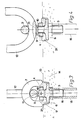
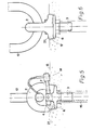
- In der Zeichnung sind drei Ausführungsbeispiele der Erfindung schematisch dargestellt.
- Es zeigen :
- Fig. 1 eine teilweise Schnittdarstellung,
- Fig. 2 eine Seitenansicht eines ersten Ausführungsbeispiels der Erfindung,
- Fig. 3 und Fig. 4 entsprechende Darstellungen, teilweise im Schnitt eines zweiten Ausführungsbeispiels der Erfindung und
- Fig. 5 und Fig. 6 entsprechende Darstellungen eines weiteren Ausführungsbeispiels der Erfindung.
- Im Ausführungsbeispiel der Fig. 1 besitzt das Ringelement 1 in Richtung der Außenfläche 13 der Last 14 wesentlich größere Abmessungen als senkrecht hierzu, so daß bei einem Zug am Zwischenglied 12 eine entsprechende Ausrichtung des Ringelements 1 eintritt. Das Zwischenglied 12 kann beispielsweise ein massiver Ring sein, der in einen Kranhaken einhängbar ist. Das Zwischenelement 12 kann aber auch eine Seilschlaufe, beispielsweise in Form einer 8 sein.
- Der Gewindebolzen 3 ist in eine Hülse 15 mit Innengewinde 16 eingeschraubt, welche Hülse 15 in der Last 14 verankert ist. In der Außenfläche 13 der Last ist eine Vertiefung 17 vorgesehen, die in der Lage ist, die Stützplatte 6, die einstückig mit dem Ringelement verbunden ist, aufzunehmen. Der Gewindebolzen 3 besitzt einen Bund 5, der dem Ringelement 1 eine Anlage gibt. Das Ringelement 1 bzw. die Stützplatte 6 werden mittels des aufgeschraubten Haltegliedes 4 in der gewünschten Stellung gehalten, wobei das Halteglied durch eine Querbohrung 18 mit einem Splint od. dergl. in der gewünschten Distanz zum Bund 5 gehalten wird. Im Halteglied 4 ist eine Feder 19 gelagert, die eine Kugel 8 in eine Vertiefung auf der Außenfläche der Stützplatte drückt. Durch geeignete Vorspannung der Feder 19 läßt sich der Gewindebolzen 3 mittels des Ringelementes 1 einschrauben. Liegt der Bund 5 an der äußeren Abdeckung 20 der Hülse 15 an, kann das Ringelement 1 über die Kugel 8 hinweggedreht werden, und beispielsweise eine halbe Umdrehung weitergedreht werden, so daß ohne Einrasten der Kugel 8 eine Ausrichtung des Ringelements entsprechend der Last möglich wird. Die Stützplatte 6 liegt dabei am Boden der Vertiefung 17 auf, um die Kräfte sicher einzuleiten.
- Beim Ausführungsbeispiel nach den Fig. 3 und 4 ist der Gewindebolzen 3 einstückig mit der Stützplatte 6 verbunden, während das Ringelement 2 mit seiner ringförmigen Platte 21 auf der Stützplatte 6 aufliegt und sich am Halteglied 4 abstützt.
- Zwischen dem Zwischenglied 12 und dem Gewindebolzen ist als Mitnehmer eine Kupplung 9 vorgesehen. Hierfür ist am Zwischenglied 12 ein Schlitz angeordnet, der als Kupplungselement 11 dient und mit einer vorstehenden Leiste 10 am Bolzen 3 zusammenwirkt.
- Beim Ausführungsbeispiel nach den Fig. 5 und 6 ist im Halteglied 4 eine Ausnehmung vorgesehen, in die der stiftartige Mitnehmer 7 eingesteckt werden kann. Dieser Stift 7 ist unverlierbar mit dem Ringelement 2 verbunden. Bei dieser Anordnung ist es möglich, mittels des Zwischengliedes 12 oder auch des Ringelementes 2 den Gewindebolzen einzuschrauben bzw. nach Gebrauch wieder herauszudrehen.
Claims (8)
Priority Applications (1)
| Application Number | Priority Date | Filing Date | Title |
|---|---|---|---|
| AT85105823T ATE41485T1 (de) | 1984-05-15 | 1985-05-11 | Ringschraube. |
Applications Claiming Priority (2)
| Application Number | Priority Date | Filing Date | Title |
|---|---|---|---|
| DE19848414736U DE8414736U1 (de) | 1984-05-15 | 1984-05-15 | Ringschraube |
| DE8414736U | 1984-05-15 |
Publications (3)
| Publication Number | Publication Date |
|---|---|
| EP0161652A2 EP0161652A2 (de) | 1985-11-21 |
| EP0161652A3 EP0161652A3 (en) | 1986-08-20 |
| EP0161652B1 true EP0161652B1 (de) | 1989-03-15 |
Family
ID=6766878
Family Applications (1)
| Application Number | Title | Priority Date | Filing Date |
|---|---|---|---|
| EP85105823A Expired EP0161652B1 (de) | 1984-05-15 | 1985-05-11 | Ringschraube |
Country Status (3)
| Country | Link |
|---|---|
| EP (1) | EP0161652B1 (de) |
| AT (1) | ATE41485T1 (de) |
| DE (2) | DE8414736U1 (de) |
Cited By (4)
| Publication number | Priority date | Publication date | Assignee | Title |
|---|---|---|---|---|
| DE4336780A1 (de) * | 1993-10-25 | 1995-04-27 | Rud Ketten Rieger & Dietz | Ringschraube |
| DE4403785A1 (de) * | 1993-10-25 | 1995-08-10 | Rud Ketten Rieger & Dietz | Ringschraube |
| WO2016140673A1 (en) * | 2015-03-05 | 2016-09-09 | The Crosby Group LLC | Rotating eye bolt assembly with lock mechanism |
| EP4006267A1 (de) * | 2020-11-30 | 2022-06-01 | Georg Weidner | Transportankersystem für betonteil |
Families Citing this family (17)
| Publication number | Priority date | Publication date | Assignee | Title |
|---|---|---|---|---|
| DE3538067A1 (de) * | 1985-10-25 | 1987-04-30 | Oerlikon Boehringer Gmbh | Einstellbare ringschraube |
| FR2624242B1 (fr) * | 1987-12-08 | 1990-03-23 | Armor Inox Sa | Dispositif de verrouillage, notamment pour portes d'enceintes rotatives sous pression |
| DE4311757A1 (de) * | 1993-04-08 | 1994-10-13 | Halfen Gmbh & Co Kg | Vorrichtung zum Ankuppeln eines Seiles einer Hebevorrichtung an ein Fertigteil |
| DE4336779C2 (de) * | 1993-10-25 | 1995-09-14 | Rud Ketten Rieger & Dietz | Anschlußvorrichtung |
| IT1284894B1 (it) * | 1996-09-30 | 1998-05-28 | Sergio Zambelli | Dispositivo per il sollevamento di manufatti prefabbricati in particolare in calcestruzzo o simili |
| FR2781022B1 (fr) * | 1998-07-10 | 2000-09-15 | Hilti France | Dispositif de fixation a anneau |
| DE10002899C2 (de) * | 2000-01-14 | 2002-01-03 | Rud Ketten Rieger & Dietz | Ringmutter |
| DE10164593B4 (de) * | 2001-12-21 | 2006-01-12 | Rud-Kettenfabrik Rieger & Dietz Gmbh U. Co. | Anschlagpunkt |
| FR2880084B1 (fr) * | 2004-12-23 | 2007-03-02 | Blaise Henrion | Dispositif de fixation du type anneau de levage |
| CN103221699B (zh) * | 2010-12-02 | 2015-06-10 | 佩瓦格奥地利有限公司 | 吊环螺栓 |
| DE202012100764U1 (de) | 2012-03-05 | 2012-04-27 | Thiele Gmbh & Co. Kg | Ringschraube |
| CN103373667B (zh) * | 2012-04-28 | 2016-12-14 | 振锋企业股份有限公司 | 物件连接装置 |
| DE202012103079U1 (de) * | 2012-08-15 | 2012-09-03 | J. D. Theile Gmbh & Co. Kg | Anschlagöse |
| US20150071732A1 (en) * | 2013-09-06 | 2015-03-12 | Yoke Industrial Corp. | Eyebolt |
| CN109795951A (zh) * | 2017-11-17 | 2019-05-24 | 振锋企业股份有限公司 | 吊环螺栓 |
| CN109502472B (zh) * | 2019-01-16 | 2023-10-27 | 广西玉柴机器股份有限公司 | 一种吊装气缸体的吊具 |
| DE102025102468A1 (de) * | 2025-01-23 | 2026-07-23 | Georg Weidner | Asymmetrische Haltescheibe für Transportanker |
Family Cites Families (3)
| Publication number | Priority date | Publication date | Assignee | Title |
|---|---|---|---|---|
| DE1500642A1 (de) * | 1966-08-30 | 1969-02-13 | American Drill Bushing Company | Befestigungsvorrichtung |
| US4174087A (en) * | 1978-03-03 | 1979-11-13 | Allen-Stevens Corp. | Swivel suspension set |
| JPS5929138Y2 (ja) * | 1982-07-23 | 1984-08-22 | 日本ノ−シヨン工業株式会社 | 合成樹脂製なす環 |
-
1984
- 1984-05-15 DE DE19848414736U patent/DE8414736U1/de not_active Expired
-
1985
- 1985-05-11 EP EP85105823A patent/EP0161652B1/de not_active Expired
- 1985-05-11 AT AT85105823T patent/ATE41485T1/de not_active IP Right Cessation
- 1985-05-11 DE DE8585105823T patent/DE3568837D1/de not_active Expired
Cited By (4)
| Publication number | Priority date | Publication date | Assignee | Title |
|---|---|---|---|---|
| DE4336780A1 (de) * | 1993-10-25 | 1995-04-27 | Rud Ketten Rieger & Dietz | Ringschraube |
| DE4403785A1 (de) * | 1993-10-25 | 1995-08-10 | Rud Ketten Rieger & Dietz | Ringschraube |
| WO2016140673A1 (en) * | 2015-03-05 | 2016-09-09 | The Crosby Group LLC | Rotating eye bolt assembly with lock mechanism |
| EP4006267A1 (de) * | 2020-11-30 | 2022-06-01 | Georg Weidner | Transportankersystem für betonteil |
Also Published As
| Publication number | Publication date |
|---|---|
| EP0161652A3 (en) | 1986-08-20 |
| EP0161652A2 (de) | 1985-11-21 |
| ATE41485T1 (de) | 1989-04-15 |
| DE3568837D1 (en) | 1989-04-20 |
| DE8414736U1 (de) | 1984-08-16 |
Similar Documents
| Publication | Publication Date | Title |
|---|---|---|
| EP0161652A2 (de) | Ringschraube | |
| EP0163008B1 (de) | Hebe- und Transportvorrichtung | |
| EP0132524A2 (de) | Einschraub-Verbindungsstück für in ein Betonfertigteil einbetonierte Hülsenanker | |
| EP3736459B1 (de) | Anschlagpunkt | |
| CH631133A5 (de) | Vorrichtung zum anhaengen eines betonfertigteils an ein hebezeug. | |
| DE3009789C2 (de) | Vorrichtung zum Ankuppeln eines Lasthebemittels an ein Betonfertigteil o.dgl. | |
| DE2708788C2 (de) | Vorrichtung zum Anhängen eines Betonfertigteils an ein Hebezeug | |
| EP0000793B1 (de) | Transportabler Mast, insbesondere für Richtfunkanlagen | |
| DE4336779C2 (de) | Anschlußvorrichtung | |
| DE3220743C2 (de) | Einrichtung zum Verzurren von Containern | |
| DE202019002916U1 (de) | Stützsystem zum Tragen eines Teils eines Bauwerks | |
| DE69419724T2 (de) | Hebering | |
| DE202012103079U1 (de) | Anschlagöse | |
| EP4353666B1 (de) | Anschlagpunkt | |
| DE9316475U1 (de) | Ringschraube | |
| DE4336780A1 (de) | Ringschraube | |
| DE3420841C2 (de) | Verbindungsvorrichtung zur Erstellung einer mehrdimensionalen Konstruktion | |
| DE2708787B2 (de) | Vorrichtung zum Anhängen eines Betonfertigteils an ein Hebezeug | |
| EP1028259B1 (de) | Befestigungsvorrichtung zur lösbaren Verankerung eines feuerfesten Bauteiles an einem metallischen Bauteil | |
| DE3538067C2 (de) | ||
| DE2617866A1 (de) | Vorrichtung zum anschlagen von betonfertigteilen | |
| DD204458A1 (de) | Lasthaken fuer liefertrommeln | |
| DE1247075B (de) | Verbindungsvorrichtung fuer zwei Bauteile | |
| DE20011873U1 (de) | Einschraubanschlagmittel für Betonfertigteile | |
| AT226569B (de) | Scharnier für die Flügel von Türen, Fernstern od. dgl. |
Legal Events
| Date | Code | Title | Description |
|---|---|---|---|
| PUAI | Public reference made under article 153(3) epc to a published international application that has entered the european phase |
Free format text: ORIGINAL CODE: 0009012 |
|
| AK | Designated contracting states |
Designated state(s): AT CH DE FR IT LI NL |
|
| PUAL | Search report despatched |
Free format text: ORIGINAL CODE: 0009013 |
|
| AK | Designated contracting states |
Kind code of ref document: A3 Designated state(s): AT CH DE FR IT LI NL |
|
| 17P | Request for examination filed |
Effective date: 19861029 |
|
| 17Q | First examination report despatched |
Effective date: 19870914 |
|
| GRAA | (expected) grant |
Free format text: ORIGINAL CODE: 0009210 |
|
| AK | Designated contracting states |
Kind code of ref document: B1 Designated state(s): AT CH DE FR IT LI NL |
|
| REF | Corresponds to: |
Ref document number: 41485 Country of ref document: AT Date of ref document: 19890415 Kind code of ref document: T |
|
| REF | Corresponds to: |
Ref document number: 3568837 Country of ref document: DE Date of ref document: 19890420 |
|
| ET | Fr: translation filed | ||
| ITF | It: translation for a ep patent filed | ||
| PLBE | No opposition filed within time limit |
Free format text: ORIGINAL CODE: 0009261 |
|
| STAA | Information on the status of an ep patent application or granted ep patent |
Free format text: STATUS: NO OPPOSITION FILED WITHIN TIME LIMIT |
|
| 26N | No opposition filed | ||
| ITTA | It: last paid annual fee | ||
| PGFP | Annual fee paid to national office [announced via postgrant information from national office to epo] |
Ref country code: AT Payment date: 19940511 Year of fee payment: 10 |
|
| PG25 | Lapsed in a contracting state [announced via postgrant information from national office to epo] |
Ref country code: AT Effective date: 19950511 |
|
| PGFP | Annual fee paid to national office [announced via postgrant information from national office to epo] |
Ref country code: FR Payment date: 19980518 Year of fee payment: 14 |
|
| PG25 | Lapsed in a contracting state [announced via postgrant information from national office to epo] |
Ref country code: FR Free format text: LAPSE BECAUSE OF NON-PAYMENT OF DUE FEES Effective date: 20000131 |
|
| REG | Reference to a national code |
Ref country code: FR Ref legal event code: ST |
|
| PGFP | Annual fee paid to national office [announced via postgrant information from national office to epo] |
Ref country code: NL Payment date: 20040518 Year of fee payment: 20 |
|
| PGFP | Annual fee paid to national office [announced via postgrant information from national office to epo] |
Ref country code: DE Payment date: 20040722 Year of fee payment: 20 |
|
| PGFP | Annual fee paid to national office [announced via postgrant information from national office to epo] |
Ref country code: CH Payment date: 20040813 Year of fee payment: 20 |
|
| PG25 | Lapsed in a contracting state [announced via postgrant information from national office to epo] |
Ref country code: NL Free format text: LAPSE BECAUSE OF EXPIRATION OF PROTECTION Effective date: 20050511 |
|
| REG | Reference to a national code |
Ref country code: CH Ref legal event code: PL |
|
| NLV7 | Nl: ceased due to reaching the maximum lifetime of a patent |
Effective date: 20050511 |