EP0161909A2 - A tubular container - Google Patents
A tubular container Download PDFInfo
- Publication number
- EP0161909A2 EP0161909A2 EP85303264A EP85303264A EP0161909A2 EP 0161909 A2 EP0161909 A2 EP 0161909A2 EP 85303264 A EP85303264 A EP 85303264A EP 85303264 A EP85303264 A EP 85303264A EP 0161909 A2 EP0161909 A2 EP 0161909A2
- Authority
- EP
- European Patent Office
- Prior art keywords
- container
- ring
- container according
- flanges
- sidewall
- Prior art date
- Legal status (The legal status is an assumption and is not a legal conclusion. Google has not performed a legal analysis and makes no representation as to the accuracy of the status listed.)
- Withdrawn
Links
Images


Classifications
-
- B—PERFORMING OPERATIONS; TRANSPORTING
- B65—CONVEYING; PACKING; STORING; HANDLING THIN OR FILAMENTARY MATERIAL
- B65D—CONTAINERS FOR STORAGE OR TRANSPORT OF ARTICLES OR MATERIALS, e.g. BAGS, BARRELS, BOTTLES, BOXES, CANS, CARTONS, CRATES, DRUMS, JARS, TANKS, HOPPERS, FORWARDING CONTAINERS; ACCESSORIES, CLOSURES, OR FITTINGS THEREFOR; PACKAGING ELEMENTS; PACKAGES
- B65D77/00—Packages formed by enclosing articles or materials in preformed containers, e.g. boxes, cartons, sacks or bags
- B65D77/04—Articles or materials enclosed in two or more containers disposed one within another
- B65D77/06—Liquids or semi-liquids or other materials or articles enclosed in flexible containers disposed within rigid containers
-
- B—PERFORMING OPERATIONS; TRANSPORTING
- B65—CONVEYING; PACKING; STORING; HANDLING THIN OR FILAMENTARY MATERIAL
- B65D—CONTAINERS FOR STORAGE OR TRANSPORT OF ARTICLES OR MATERIALS, e.g. BAGS, BARRELS, BOTTLES, BOXES, CANS, CARTONS, CRATES, DRUMS, JARS, TANKS, HOPPERS, FORWARDING CONTAINERS; ACCESSORIES, CLOSURES, OR FITTINGS THEREFOR; PACKAGING ELEMENTS; PACKAGES
- B65D43/00—Lids or covers for rigid or semi-rigid containers
- B65D43/02—Removable lids or covers
- B65D43/0202—Removable lids or covers without integral tamper element
- B65D43/0214—Removable lids or covers without integral tamper element secured only by friction or gravity
- B65D43/022—Removable lids or covers without integral tamper element secured only by friction or gravity only on the inside, or a part turned to the inside, of the mouth of the container
-
- B—PERFORMING OPERATIONS; TRANSPORTING
- B65—CONVEYING; PACKING; STORING; HANDLING THIN OR FILAMENTARY MATERIAL
- B65D—CONTAINERS FOR STORAGE OR TRANSPORT OF ARTICLES OR MATERIALS, e.g. BAGS, BARRELS, BOTTLES, BOXES, CANS, CARTONS, CRATES, DRUMS, JARS, TANKS, HOPPERS, FORWARDING CONTAINERS; ACCESSORIES, CLOSURES, OR FITTINGS THEREFOR; PACKAGING ELEMENTS; PACKAGES
- B65D51/00—Closures not otherwise provided for
- B65D51/24—Closures not otherwise provided for combined or co-operating with auxiliary devices for non-closing purposes
- B65D51/242—Closures not otherwise provided for combined or co-operating with auxiliary devices for non-closing purposes provided with means for facilitating lifting or suspending of the container
-
- B—PERFORMING OPERATIONS; TRANSPORTING
- B65—CONVEYING; PACKING; STORING; HANDLING THIN OR FILAMENTARY MATERIAL
- B65D—CONTAINERS FOR STORAGE OR TRANSPORT OF ARTICLES OR MATERIALS, e.g. BAGS, BARRELS, BOTTLES, BOXES, CANS, CARTONS, CRATES, DRUMS, JARS, TANKS, HOPPERS, FORWARDING CONTAINERS; ACCESSORIES, CLOSURES, OR FITTINGS THEREFOR; PACKAGING ELEMENTS; PACKAGES
- B65D2543/00—Lids or covers essentially for box-like containers
- B65D2543/00009—Details of lids or covers for rigid or semi-rigid containers
- B65D2543/00018—Overall construction of the lid
- B65D2543/00064—Shape of the outer periphery
- B65D2543/00074—Shape of the outer periphery curved
- B65D2543/00083—Shape of the outer periphery curved oval
-
- B—PERFORMING OPERATIONS; TRANSPORTING
- B65—CONVEYING; PACKING; STORING; HANDLING THIN OR FILAMENTARY MATERIAL
- B65D—CONTAINERS FOR STORAGE OR TRANSPORT OF ARTICLES OR MATERIALS, e.g. BAGS, BARRELS, BOTTLES, BOXES, CANS, CARTONS, CRATES, DRUMS, JARS, TANKS, HOPPERS, FORWARDING CONTAINERS; ACCESSORIES, CLOSURES, OR FITTINGS THEREFOR; PACKAGING ELEMENTS; PACKAGES
- B65D2543/00—Lids or covers essentially for box-like containers
- B65D2543/00009—Details of lids or covers for rigid or semi-rigid containers
- B65D2543/00018—Overall construction of the lid
- B65D2543/00064—Shape of the outer periphery
- B65D2543/00074—Shape of the outer periphery curved
- B65D2543/00092—Shape of the outer periphery curved circular
-
- B—PERFORMING OPERATIONS; TRANSPORTING
- B65—CONVEYING; PACKING; STORING; HANDLING THIN OR FILAMENTARY MATERIAL
- B65D—CONTAINERS FOR STORAGE OR TRANSPORT OF ARTICLES OR MATERIALS, e.g. BAGS, BARRELS, BOTTLES, BOXES, CANS, CARTONS, CRATES, DRUMS, JARS, TANKS, HOPPERS, FORWARDING CONTAINERS; ACCESSORIES, CLOSURES, OR FITTINGS THEREFOR; PACKAGING ELEMENTS; PACKAGES
- B65D2543/00—Lids or covers essentially for box-like containers
- B65D2543/00009—Details of lids or covers for rigid or semi-rigid containers
- B65D2543/00018—Overall construction of the lid
- B65D2543/00259—Materials used
- B65D2543/00277—Metal
-
- B—PERFORMING OPERATIONS; TRANSPORTING
- B65—CONVEYING; PACKING; STORING; HANDLING THIN OR FILAMENTARY MATERIAL
- B65D—CONTAINERS FOR STORAGE OR TRANSPORT OF ARTICLES OR MATERIALS, e.g. BAGS, BARRELS, BOTTLES, BOXES, CANS, CARTONS, CRATES, DRUMS, JARS, TANKS, HOPPERS, FORWARDING CONTAINERS; ACCESSORIES, CLOSURES, OR FITTINGS THEREFOR; PACKAGING ELEMENTS; PACKAGES
- B65D2543/00—Lids or covers essentially for box-like containers
- B65D2543/00009—Details of lids or covers for rigid or semi-rigid containers
- B65D2543/00444—Contact between the container and the lid
- B65D2543/00481—Contact between the container and the lid on the inside or the outside of the container
- B65D2543/0049—Contact between the container and the lid on the inside or the outside of the container on the inside, or a part turned to the inside of the mouth of the container
- B65D2543/00509—Cup
-
- B—PERFORMING OPERATIONS; TRANSPORTING
- B65—CONVEYING; PACKING; STORING; HANDLING THIN OR FILAMENTARY MATERIAL
- B65D—CONTAINERS FOR STORAGE OR TRANSPORT OF ARTICLES OR MATERIALS, e.g. BAGS, BARRELS, BOTTLES, BOXES, CANS, CARTONS, CRATES, DRUMS, JARS, TANKS, HOPPERS, FORWARDING CONTAINERS; ACCESSORIES, CLOSURES, OR FITTINGS THEREFOR; PACKAGING ELEMENTS; PACKAGES
- B65D2543/00—Lids or covers essentially for box-like containers
- B65D2543/00009—Details of lids or covers for rigid or semi-rigid containers
- B65D2543/00444—Contact between the container and the lid
- B65D2543/00481—Contact between the container and the lid on the inside or the outside of the container
- B65D2543/00537—Contact between the container and the lid on the inside or the outside of the container on the outside, or a part turned to the outside of the mouth of the container
- B65D2543/00546—NO contact
-
- B—PERFORMING OPERATIONS; TRANSPORTING
- B65—CONVEYING; PACKING; STORING; HANDLING THIN OR FILAMENTARY MATERIAL
- B65D—CONTAINERS FOR STORAGE OR TRANSPORT OF ARTICLES OR MATERIALS, e.g. BAGS, BARRELS, BOTTLES, BOXES, CANS, CARTONS, CRATES, DRUMS, JARS, TANKS, HOPPERS, FORWARDING CONTAINERS; ACCESSORIES, CLOSURES, OR FITTINGS THEREFOR; PACKAGING ELEMENTS; PACKAGES
- B65D2543/00—Lids or covers essentially for box-like containers
- B65D2543/00009—Details of lids or covers for rigid or semi-rigid containers
- B65D2543/00444—Contact between the container and the lid
- B65D2543/00564—Contact between the container and the lid indirect by means of a gasket or similar intermediate ring
-
- B—PERFORMING OPERATIONS; TRANSPORTING
- B65—CONVEYING; PACKING; STORING; HANDLING THIN OR FILAMENTARY MATERIAL
- B65D—CONTAINERS FOR STORAGE OR TRANSPORT OF ARTICLES OR MATERIALS, e.g. BAGS, BARRELS, BOTTLES, BOXES, CANS, CARTONS, CRATES, DRUMS, JARS, TANKS, HOPPERS, FORWARDING CONTAINERS; ACCESSORIES, CLOSURES, OR FITTINGS THEREFOR; PACKAGING ELEMENTS; PACKAGES
- B65D2543/00—Lids or covers essentially for box-like containers
- B65D2543/00009—Details of lids or covers for rigid or semi-rigid containers
- B65D2543/00824—Means for facilitating removing of the closure
- B65D2543/00833—Integral tabs, tongues, handles or similar
- B65D2543/00851—Integral tabs, tongues, handles or similar on the central part of the lid
-
- B—PERFORMING OPERATIONS; TRANSPORTING
- B65—CONVEYING; PACKING; STORING; HANDLING THIN OR FILAMENTARY MATERIAL
- B65D—CONTAINERS FOR STORAGE OR TRANSPORT OF ARTICLES OR MATERIALS, e.g. BAGS, BARRELS, BOTTLES, BOXES, CANS, CARTONS, CRATES, DRUMS, JARS, TANKS, HOPPERS, FORWARDING CONTAINERS; ACCESSORIES, CLOSURES, OR FITTINGS THEREFOR; PACKAGING ELEMENTS; PACKAGES
- B65D2543/00—Lids or covers essentially for box-like containers
- B65D2543/00009—Details of lids or covers for rigid or semi-rigid containers
- B65D2543/00953—Sealing means
- B65D2543/00962—Sealing means inserted
- B65D2543/00972—Collars or rings
Definitions
- THE PRESENT INVENTION relates to a tubular container, and more particularly to such a container provided with a device for gripping the sidewalls thereof, such as a device for lifting the container.
- Tubular containers are now becoming more popular and are frequently used for packaging various products, such as solids or liquids which may be retained within a plastic bag located within the tubular container.
- One prior proposed gripping insert is of concave shape and is formed of relatively thin material having radially extending expansion slots. This does not ensure an evenly distributed contact between the outer edge of the gripping insert and the inside of the wall of the tube. This increases the possibility of the insert pulling out of the tube when the tube is being carried by means of the gripping insert. -This is clearly undesirable.
- a container said container being of tubular configuration and having a base and an upstanding sidewall defining on open mouth, the container being provided with an element tnsertabk into the mouth of the container, said element carrying peripheral wedging means which, when the element is in the open mouth of the container are adjacent the inner surface of the sidewall of the container, therebeing engagement means located between said wedging means and the said inner surface of the sidewall of the container so that if said wedging means are moved upwardly towards the mouth of the container, said wedging means bias the engagement means into firm contact with the interior of the side wall of the container thus retaining said element firmly in position.
- said element is a carrying element and is provided with a manually graspable handle accessible from the exterior of the container.
- said element defines a peripheral flared sidewall which constitutes said wedging means.
- a lip or rib is provided which extends radially outwardly beyond the top of the flared sidewall provided on said element.
- Said element may be fabricated as an injection moulding of a plastics material.
- the engagement means comprises a broken ring of material having a high coefficient of friction adapted to engage said wedging means and also adopted to engage the inner periphery of the sidewall of the container.
- said ring is a broken ring.
- said ring has a cross section such that the radially innermost part of the cross section constitutes an inclined wall having an angte of inclination corresponding to the angle of inclination of said wedging means.
- said ring is provided with a plurality of gripping flanges on the exterior thereof.
- said flanges comprise a plurality of sets of flanges each occupying a predetermined angle of arc, the sets of flanges being spaced apart by portions of the ring not provided with flanges.
- Said flanges may be substantially planar flanges, or may be substantially triangular flanges.
- the container may be substantially circular cross section, or of substantially oval cross section.
- the ring may comprise two separate parts, or comprises two parts interconnected by a part of reduced cross section.
- the container is such that when said element is pushed inwardly into the container, means provided on said element engage said engagement member and move the engagement member into the container with said element.
- the container may contain a bag of resilient material which, in turn, contains a carbonated beverage.
- a cylindrical container I having a substantially flat base 2, and an upstanding side wall 2 which is circular in plan, having an open mouth or top 3.
- a gripping device 4 is provided in the open mouth of the container I.
- the gripping device comprises a gripping disc 5 which is provided, adjacent the periphery thereof, with a depending side wall 6.
- the sidewall 6 is slightly flared in that the lower part of the side wall 6 has a slightly greater overall diameter than the upper part which is connected to the gripping disc 5.
- Centrally provided in the gripping disc is a manually graspable handle 7.
- the gripping disc 5 is provided with a peripheral lip 8 which extends radially beyond the top of the sidewall 6.
- the gripping disc 5, within its associated side wall 6, is dimensioned to be freely insertable in the open mouth of the container 4.
- a gripping ring 9 is provided, which is a broken ring.
- the gripping ring 9 is substantially a complete ring, but a small part 10 of the ring is missing.
- the ring is made of a material having a high coefficient of friction, such as rubber or a plastic material.
- the cross section of the ring can be seen most clearly in Figure 3, and it can be seen that the ring is of generally rectangular configuration. However, it is to be noted that the vertical side wall I of the rectangular cross section that is radially innermost is slightly inclined, (so that the ring is thicker at the top than it is at the bottom) the ongte of inclination corresponding to the angle of inclination of the depending side wall 6 mentioned above.
- the exterior of the ring is provided with a plurality of sets of parallel outwardly extending gripping flanges or ribs 12.
- Each set of flanges extends over approximately 35 0 of arc, and the sets of flanges are spaced apart by approximately 10° of arc.
- the gripping ring will initially be placed around the depending side wall 6 and as the disc 5, with the gripping ring 9 mounted thereon, is inserted in the open mouth 3 of the container I, the gripping ring will be retained in position between the depending side wall 6 and the side wall 2 of the container 1. If a downward pressure is applied to the handle 7 the plate 5 will move downwardly and the lip 8 on the plate which protrudes beyond the side wall 6 will engage the upper surface of the ring 9. The ring 9 will then move downwardly as the plate 5 moves downwardly.
- the flanges 12 provided on the exterior of the ring 9 will tend to grip the inner surface of the wall 2 of the container I retaining the gripping ring in position relative to the container I, and thus the disc 5 and the associated depending side wall 6 will move upwardly relative to the gripping ring 9.
- the side wall will effect a wedging action on the gripping ring 9 and will urge the ring 9 radially outwardly into very firm gripping engagement with the side wall 2 of the container I.
- the arrangement will be such that after the sidewall 6 has moved upwardly by a predetermined amount relative to the gripping ring 9, it will not be possible for the side wall to move further upwardly.
- a container of the type described above may be utilised to contain a flexible bag formed of a plastics material or an appropriate laminate which may contain a carbonated beverage such as beer, lemonade, cola or the like.
- the bag would be provided with a tap, accessible from the exterior of the container, to permit the beverage within the bag to be dispensed.
- a continual pressure is applied to the bag the risk of the beverage degasifying or going "flat" is minimised.
- the entire gripping assembly 4 may be fabricated as an injection moulding from a plastics material.
- Figure 4 corresponds to Figure 1 but shows a modified embodiment of the invention.
- the closure 4' is provided with a dome shaped disc 5', the slightly flared peripheral side wall 6" effectively extending upwardly from the periphery dome shaped disc 5.
- the disc 5' has a central handle 7.
- Reinforcing webs 3 are provided between the disc 5' and the side wall 6'.
- a bead 8' is provided at the upper end of the side wall 6' to engage the broken sealing ring 9'.
- the closure 4' may be fabricated as an injection moulding of plastics material.
- the seating ring 9' has a single series of flanges 12' which extend entirely around the sealing ring, and the flanges are of triangular configuration. This embodiment will operate in the same way as the embodiment shown in Figures I to 3.
- the invention has been described with reference to embodiments primarily intended for use in connection with certain containers of circular hortzontal cross section, it is to be realised that the invention may be utilised with containers of oval cross section. In such an arrangement, however, the gripping may need to be formed of two separate parts, or two parts interconnected by a part of reduced thickness.
Landscapes
- Engineering & Computer Science (AREA)
- Mechanical Engineering (AREA)
- Details Of Rigid Or Semi-Rigid Containers (AREA)
- Closures For Containers (AREA)
Abstract
A container is provided with a closure lid with a peripheral flared wall. A ring of material having a high coefficient of friction engages the flared wall and can also engage the interior of the open mouth of a container. When the element and the ring are located in position an upward force applied to the element will wedge the ring into firm contact with the interior of the container thus securing the element in position. The element may be used to carry the container or to apply pressure to a bag of carbonated beverage located within the container.
Description
- THE PRESENT INVENTION relates to a tubular container, and more particularly to such a container provided with a device for gripping the sidewalls thereof, such as a device for lifting the container.
- Tubular containers are now becoming more popular and are frequently used for packaging various products, such as solids or liquids which may be retained within a plastic bag located within the tubular container.
- It has been proposed to provide an insert which can be slidably inserted in the upper part of a tubular container, the insert being provided with a handle and being arranged so that when an upward force is applied to the handle the insert will grip the interior wall of the tube, thus enabling the tubular container to be lifted by means of the insert.
- Many prior proposed gripping inserts of this type have the shortcoming that the parts of the gripping insert designed to engage or grip the interior wall surface of the tube exert an extreme pressure on the wall of the tube, since often sharp engagement points or tangs are provided. This can result in the puncturing of the wall of the container.
- One prior proposed gripping insert is of concave shape and is formed of relatively thin material having radially extending expansion slots. This does not ensure an evenly distributed contact between the outer edge of the gripping insert and the inside of the wall of the tube. This increases the possibility of the insert pulling out of the tube when the tube is being carried by means of the gripping insert. -This is clearly undesirable.
- According to this invention there is provided a container, said container being of tubular configuration and having a base and an upstanding sidewall defining on open mouth, the container being provided with an element tnsertabk into the mouth of the container, said element carrying peripheral wedging means which, when the element is in the open mouth of the container are adjacent the inner surface of the sidewall of the container, therebeing engagement means located between said wedging means and the said inner surface of the sidewall of the container so that if said wedging means are moved upwardly towards the mouth of the container, said wedging means bias the engagement means into firm contact with the interior of the side wall of the container thus retaining said element firmly in position.
- Preferably said element is a carrying element and is provided with a manually graspable handle accessible from the exterior of the container.
- Conveniently said element defines a peripheral flared sidewall which constitutes said wedging means.
- Advantageously a lip or rib is provided which extends radially outwardly beyond the top of the flared sidewall provided on said element.
- Said element may be fabricated as an injection moulding of a plastics material.
- In a preferred embodiment the engagement means comprises a broken ring of material having a high coefficient of friction adapted to engage said wedging means and also adopted to engage the inner periphery of the sidewall of the container.
- Preferably said ring is a broken ring.
- Conveniently said ring has a cross section such that the radially innermost part of the cross section constitutes an inclined wall having an angte of inclination corresponding to the angle of inclination of said wedging means.
- Advantageously said ring is provided with a plurality of gripping flanges on the exterior thereof.
- Preferably said flanges comprise a plurality of sets of flanges each occupying a predetermined angle of arc, the sets of flanges being spaced apart by portions of the ring not provided with flanges.
- Said flanges may be substantially planar flanges, or may be substantially triangular flanges.
- The container may be substantially circular cross section, or of substantially oval cross section. In the latter case the ring may comprise two separate parts, or comprises two parts interconnected by a part of reduced cross section.
- Preferably the container is such that when said element is pushed inwardly into the container, means provided on said element engage said engagement member and move the engagement member into the container with said element.
- The container may contain a bag of resilient material which, in turn, contains a carbonated beverage.
- In order that the present invention may be more readily understood, and so that further features thereof may be appreciated, the invention will now be described, by way of example, with reference to the accompanying drawings in which:
- FIGURE I is a side elevational view of a container provided with a gripping device in accordance with the invention, with parts of the container being cut away for the sake of clarity of illustration,
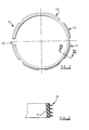
- FIGURE 2 is a plan view of a gripping ring forming part of the arrangement illustrated in Figure I,
- FIGURE 3 is an enlarged cross section through the gripping ring of Figure 2 taken on the line and
- FIGURE 4 is an exploded view of a container and a second embodiment of a gripping device embodying the invention, with parts of the container being cut away.
- Referring initially to Figure I of the accompanying drawings, a cylindrical container I is shown having a substantially
flat base 2, and anupstanding side wall 2 which is circular in plan, having an open mouth ortop 3. - A
gripping device 4 is provided in the open mouth of the container I. The gripping device comprises agripping disc 5 which is provided, adjacent the periphery thereof, with a dependingside wall 6. Thesidewall 6 is slightly flared in that the lower part of theside wall 6 has a slightly greater overall diameter than the upper part which is connected to thegripping disc 5. Centrally provided in the gripping disc is a manuallygraspable handle 7. Thegripping disc 5 is provided with aperipheral lip 8 which extends radially beyond the top of thesidewall 6. - The
gripping disc 5, within its associatedside wall 6, is dimensioned to be freely insertable in the open mouth of thecontainer 4. - A
gripping ring 9 is provided, which is a broken ring. Thus thegripping ring 9 is substantially a complete ring, but asmall part 10 of the ring is missing. The ring is made of a material having a high coefficient of friction, such as rubber or a plastic material. The cross section of the ring can be seen most clearly in Figure 3, and it can be seen that the ring is of generally rectangular configuration. However, it is to be noted that the vertical side wall I of the rectangular cross section that is radially innermost is slightly inclined, (so that the ring is thicker at the top than it is at the bottom) the ongte of inclination corresponding to the angle of inclination of the dependingside wall 6 mentioned above. The exterior of the ring is provided with a plurality of sets of parallel outwardly extending gripping flanges orribs 12. Each set of flanges extends over approximately 350 of arc, and the sets of flanges are spaced apart by approximately 10° of arc. - The gripping ring will initially be placed around the depending
side wall 6 and as thedisc 5, with thegripping ring 9 mounted thereon, is inserted in theopen mouth 3 of the container I, the gripping ring will be retained in position between the dependingside wall 6 and theside wall 2 of thecontainer 1. If a downward pressure is applied to thehandle 7 theplate 5 will move downwardly and thelip 8 on the plate which protrudes beyond theside wall 6 will engage the upper surface of thering 9. Thering 9 will then move downwardly as theplate 5 moves downwardly. If, however, an upward force is applied to thehandle 7 theflanges 12 provided on the exterior of thering 9 will tend to grip the inner surface of thewall 2 of the container I retaining the gripping ring in position relative to the container I, and thus thedisc 5 and the associated dependingside wall 6 will move upwardly relative to thegripping ring 9. As thedisc 5 and associatedside wall 6 move upwardly, by virtue of the configuration of theside wall 6, the side wall will effect a wedging action on thegripping ring 9 and will urge thering 9 radially outwardly into very firm gripping engagement with theside wall 2 of the container I. The arrangement will be such that after thesidewall 6 has moved upwardly by a predetermined amount relative to the grippingring 9, it will not be possible for the side wall to move further upwardly. - It will then be possible to carry the container utilising the
handle 7. - It is envisaged that a container of the type described above may be utilised to contain a flexible bag formed of a plastics material or an appropriate laminate which may contain a carbonated beverage such as beer, lemonade, cola or the like. The bag would be provided with a tap, accessible from the exterior of the container, to permit the beverage within the bag to be dispensed. In such a situation it would be desirable to apply a continuous pressure to the bag, especially when part of the beverage initially contained with the bag has been dispensed, since otherwise the remaining beverage in the bag may degassify or become "flat", the gas present in the beverage then entering the space available above the beverage within the bag. However, if a continual pressure is applied to the bag the risk of the beverage degasifying or going "flat" is minimised.
- It is to be appreciated that if a bag of beverage of the type described above is located in a container as illustrated in Figures I to 3, it would be possible, when part of the beverage being dispensed, to apply a downward force to the
handle 7, thus reducing the gripping action between the dependingside wall 6 and thegripping ring 9. Thedisc 5 could then be moved downwardly until a pressure is being exerted on the bag within thecontainer 1. During this downward movement, by virtue of the engagement of thelip 8 and thering 9, thering 9 will move downwardly with thedisc 5. Subsequently a slight upward pressure applied to thehandle 7 will again lock theplate 5 in position. - The
entire gripping assembly 4 may be fabricated as an injection moulding from a plastics material. - Figure 4 corresponds to Figure 1 but shows a modified embodiment of the invention. In this particular embodiment the closure 4' is provided with a dome shaped disc 5', the slightly flared
peripheral side wall 6" effectively extending upwardly from the periphery dome shapeddisc 5. The disc 5' has acentral handle 7. Reinforcingwebs 3 are provided between the disc 5' and the side wall 6'. A bead 8' is provided at the upper end of the side wall 6' to engage the broken sealing ring 9'. The closure 4' may be fabricated as an injection moulding of plastics material. The seating ring 9' has a single series of flanges 12' which extend entirely around the sealing ring, and the flanges are of triangular configuration. This embodiment will operate in the same way as the embodiment shown in Figures I to 3. - Whilst the invention has been described with reference to embodiments primarily intended for use in connection with certain containers of circular hortzontal cross section, it is to be realised that the invention may be utilised with containers of oval cross section. In such an arrangement, however, the gripping may need to be formed of two separate parts, or two parts interconnected by a part of reduced thickness.
Claims (10)
- I. A container, said container being of tubular configuration and having a base and an upstanding sidewall defining an open mouth, the container being provided with an element insertable into the mouth of the container, said element carrying peripheral wedging means which, when the element is in the open mouth of the container are adjacent the inner surface of the sidewall of the container, therebeing engagement means located between said wedging means and the said inner surface of the sidewall of the container so that if said wedging means are moved upwardly towards the mouth of the container, said wedging means bias the engagement means into firm contact with the interior of the side wall of the container thus retaining said element firmly in position.
- 2. A container according to claim I wherein said element is a carrying element and is provided with a manually graspable handle accessible from the exterior of the container.
- 3. A container according to claim I or claim 2 wherein said element defines a peripheral flared sidewall which constitutes said wedging means.
- 4. A container according to claim 3 wherein a lip or rib is provided which extends radially outwardly beyond the top of the flared sidewall provided on said element.
- 5. A container according to any one of the preceding claims wherein the engagement means comprises a broken ring of material having a high coefficient of friction adapted to engage said wedging means and also adapted to engage the inner periphery of the sidewall of the container.
- 6. A container according to claim 5, wherein said ring has a cross section such that the radially innermost part of the cross section constitutes an inclined wall having an angle of inclination corresponding to the angle of inclination of said wedging means.
- 7. A container according to claim 5 or 6, wherein said ring is provided with a plurality of gripping flanges on the exterior thereof.
- 8. A container according to claim 7 wherein said flanges comprise a plurality of sets of flanges each occupying a predetermined angle of arc, the sets of flanges being spaced apart by portions of the ring not provided with flanges.
- 9. A container according to any one of the preceding claims of oval cross-section, wherein the ring comprises two separate parts, or comprises two parts interconnected by a part of reduced cross section.
- 10. A container according to any one of the preceding claims containing a bag of resilient material which, in turn, contains a carbonated beverage.
Applications Claiming Priority (2)
| Application Number | Priority Date | Filing Date | Title |
|---|---|---|---|
| GB8412175 | 1984-05-12 | ||
| GB848412175A GB8412175D0 (en) | 1984-05-12 | 1984-05-12 | Gripping device |
Publications (2)
| Publication Number | Publication Date |
|---|---|
| EP0161909A2 true EP0161909A2 (en) | 1985-11-21 |
| EP0161909A3 EP0161909A3 (en) | 1986-12-10 |
Family
ID=10560860
Family Applications (1)
| Application Number | Title | Priority Date | Filing Date |
|---|---|---|---|
| EP85303264A Withdrawn EP0161909A3 (en) | 1984-05-12 | 1985-05-08 | A tubular container |
Country Status (3)
| Country | Link |
|---|---|
| EP (1) | EP0161909A3 (en) |
| AU (1) | AU4229285A (en) |
| GB (1) | GB8412175D0 (en) |
Cited By (6)
| Publication number | Priority date | Publication date | Assignee | Title |
|---|---|---|---|---|
| FR2704210A1 (en) * | 1993-04-20 | 1994-10-28 | Defaut Marie Christine | Device for fixing a lid on a container which can be used at a distance by means of a manipulator arm |
| WO2001042090A3 (en) * | 1999-12-07 | 2001-12-06 | Perna Pty Ltd | Storage and dispensing of carbonated beverages |
| WO2002030757A3 (en) * | 2000-10-11 | 2002-06-13 | Bantix Pty Ltd | Variable volume container for a liquified gas fluid |
| WO2017139759A1 (en) * | 2016-02-12 | 2017-08-17 | The Sherwin-Williams Company | Storage container |
| CN110861835A (en) * | 2019-12-11 | 2020-03-06 | 徐州蓝湖信息科技有限公司 | Sealed storage box of portable for commodity circulation transportation |
| EP4265538A1 (en) * | 2022-04-22 | 2023-10-25 | Sleade e.U. | Multi-path package |
Family Cites Families (5)
| Publication number | Priority date | Publication date | Assignee | Title |
|---|---|---|---|---|
| NL36604C (en) * | 1900-01-01 | |||
| US2746632A (en) * | 1953-11-27 | 1956-05-22 | Aladdin Ind Inc | Flexible bottle closure |
| US3164289A (en) * | 1962-12-14 | 1965-01-05 | Thomas A Cocchiarella | Hermetically sealable container lid |
| US3924774A (en) * | 1972-10-11 | 1975-12-09 | John H Donnelly | Closure for containers |
| US4245753A (en) * | 1979-10-04 | 1981-01-20 | Ellis Henry D | Container for paint |
-
1984
- 1984-05-12 GB GB848412175A patent/GB8412175D0/en active Pending
-
1985
- 1985-05-08 EP EP85303264A patent/EP0161909A3/en not_active Withdrawn
- 1985-05-10 AU AU42292/85A patent/AU4229285A/en not_active Abandoned
Cited By (9)
| Publication number | Priority date | Publication date | Assignee | Title |
|---|---|---|---|---|
| FR2704210A1 (en) * | 1993-04-20 | 1994-10-28 | Defaut Marie Christine | Device for fixing a lid on a container which can be used at a distance by means of a manipulator arm |
| WO2001042090A3 (en) * | 1999-12-07 | 2001-12-06 | Perna Pty Ltd | Storage and dispensing of carbonated beverages |
| US6789707B2 (en) | 1999-12-07 | 2004-09-14 | Perna Pty. Ltd. | Storage and dispensing of carbonated beverages |
| US7137538B2 (en) | 1999-12-07 | 2006-11-21 | Perna Pty Ltd. | Storage and dispensing of carbonated beverages |
| WO2002030757A3 (en) * | 2000-10-11 | 2002-06-13 | Bantix Pty Ltd | Variable volume container for a liquified gas fluid |
| WO2017139759A1 (en) * | 2016-02-12 | 2017-08-17 | The Sherwin-Williams Company | Storage container |
| US10717580B2 (en) | 2016-02-12 | 2020-07-21 | The Sherwin-Williams Company | Storage container |
| CN110861835A (en) * | 2019-12-11 | 2020-03-06 | 徐州蓝湖信息科技有限公司 | Sealed storage box of portable for commodity circulation transportation |
| EP4265538A1 (en) * | 2022-04-22 | 2023-10-25 | Sleade e.U. | Multi-path package |
Also Published As
| Publication number | Publication date |
|---|---|
| GB8412175D0 (en) | 1984-06-20 |
| EP0161909A3 (en) | 1986-12-10 |
| AU4229285A (en) | 1985-11-14 |
Similar Documents
| Publication | Publication Date | Title |
|---|---|---|
| US4917258A (en) | Snap-on lid for opened soft drink cans | |
| US6401964B1 (en) | Portable insulating receptacles | |
| CA2079852C (en) | Closure assembly with separable seal | |
| US4660876A (en) | Reusable bottle handle | |
| US2988258A (en) | Cup | |
| US5425467A (en) | Bowl lid having integral lever mechanism | |
| EP0193336B1 (en) | Packages for carbonated beverages and method therefor | |
| US3840152A (en) | Sealable and resealable container | |
| US5147059A (en) | Seal with automatic release | |
| US5176278A (en) | Beverage can resealing device | |
| US3142409A (en) | Container and cover | |
| AU771912B2 (en) | Container with separate storage spaces | |
| EP0668834B1 (en) | Stackable mug | |
| US3112841A (en) | Closure or lid | |
| US5799814A (en) | Drink-through lid for container | |
| EP0790192A2 (en) | Shaker for condiments | |
| MXPA03004955A (en) | Plastic paint can. | |
| JPS643750B2 (en) | ||
| CA2311511A1 (en) | Stackable re-usable container | |
| EP0161909A2 (en) | A tubular container | |
| US5148935A (en) | Venting resealable container closure and associated closure container-combination | |
| UA80972C2 (en) | Cup-shaped receptacle (variants) and lid for it (variants) | |
| US3206019A (en) | Can fastener | |
| US3321124A (en) | Container lid | |
| EP0191616A2 (en) | Container |
Legal Events
| Date | Code | Title | Description |
|---|---|---|---|
| PUAI | Public reference made under article 153(3) epc to a published international application that has entered the european phase |
Free format text: ORIGINAL CODE: 0009012 |
|
| AK | Designated contracting states |
Designated state(s): AT BE CH DE FR GB IT LI LU NL SE |
|
| PUAL | Search report despatched |
Free format text: ORIGINAL CODE: 0009013 |
|
| AK | Designated contracting states |
Kind code of ref document: A3 Designated state(s): AT BE CH DE FR GB IT LI LU NL SE |
|
| STAA | Information on the status of an ep patent application or granted ep patent |
Free format text: STATUS: THE APPLICATION IS DEEMED TO BE WITHDRAWN |
|
| 18D | Application deemed to be withdrawn |
Effective date: 19870611 |