EP0163914A1 - Schweissmethode für Schneidsegmente - Google Patents
Schweissmethode für Schneidsegmente Download PDFInfo
- Publication number
- EP0163914A1 EP0163914A1 EP85105044A EP85105044A EP0163914A1 EP 0163914 A1 EP0163914 A1 EP 0163914A1 EP 85105044 A EP85105044 A EP 85105044A EP 85105044 A EP85105044 A EP 85105044A EP 0163914 A1 EP0163914 A1 EP 0163914A1
- Authority
- EP
- European Patent Office
- Prior art keywords
- core body
- segment
- core
- grits
- cutter
- Prior art date
- Legal status (The legal status is an assumption and is not a legal conclusion. Google has not performed a legal analysis and makes no representation as to the accuracy of the status listed.)
- Granted
Links
Images

Classifications
-
- B—PERFORMING OPERATIONS; TRANSPORTING
- B28—WORKING CEMENT, CLAY, OR STONE
- B28D—WORKING STONE OR STONE-LIKE MATERIALS
- B28D1/00—Working stone or stone-like materials, e.g. brick, concrete or glass, not provided for elsewhere; Machines, devices, tools therefor
- B28D1/02—Working stone or stone-like materials, e.g. brick, concrete or glass, not provided for elsewhere; Machines, devices, tools therefor by sawing
- B28D1/12—Saw-blades or saw-discs specially adapted for working stone
- B28D1/121—Circular saw blades
-
- B—PERFORMING OPERATIONS; TRANSPORTING
- B23—MACHINE TOOLS; METAL-WORKING NOT OTHERWISE PROVIDED FOR
- B23D—PLANING; SLOTTING; SHEARING; BROACHING; SAWING; FILING; SCRAPING; LIKE OPERATIONS FOR WORKING METAL BY REMOVING MATERIAL, NOT OTHERWISE PROVIDED FOR
- B23D65/00—Making tools for sawing machines or sawing devices for use in cutting any kind of material
-
- B—PERFORMING OPERATIONS; TRANSPORTING
- B23—MACHINE TOOLS; METAL-WORKING NOT OTHERWISE PROVIDED FOR
- B23K—SOLDERING OR UNSOLDERING; WELDING; CLADDING OR PLATING BY SOLDERING OR WELDING; CUTTING BY APPLYING HEAT LOCALLY, e.g. FLAME CUTTING; WORKING BY LASER BEAM
- B23K31/00—Processes relevant to this subclass, specially adapted for particular articles or purposes, but not covered by any single one of main groups B23K1/00 - B23K28/00
- B23K31/02—Processes relevant to this subclass, specially adapted for particular articles or purposes, but not covered by any single one of main groups B23K1/00 - B23K28/00 relating to soldering or welding
- B23K31/025—Connecting cutting edges or the like to tools; Attaching reinforcements to workpieces, e.g. wear-resisting zones to tableware
Definitions
- the present invention relates to a method for ' producing a cutter, and more particularly to a method for welding cutter segments composed of sintered compacts, which comprise diamond- or CBN (cubic boron nitride)-grits, to a core body.
- sintered compacts which comprise diamond- or CBN (cubic boron nitride)-grits
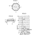
- Fig. 1 shows a conventional method of fixing cutter-segments that contain diamonds onto a core body.
- a circular blade as shown is mounted on a motor-driven shaft (not shown) by, for example, use of a center hole 2a and is used as a handy cutter, for such operations as (1) cutting bricks, slates and tiles, (2) trimming stone blocks, (3) cutting iron sheets, concrete pipes and concrete blocks, (4) grooving concrete roads, (5) forming curved surfaces on stone blocks, (6) chamfering stone blocks and (7) beveling stone blocks.
- the numeral 2 denotes a steel core
- the numeral 1 is a cutter segment made of a mixture of bond powder, such as Co (cobalt), and diamond- or CBN-grits, which has been compacted and sintered (in most cases, by hot pressing) to nearly 100% apparent density.
- Such segments are fixed onto the core 2 by brazing to make a cutter blade.
- the multi-segment circular cutter made by the above conventional process has defects and problems as described below:
- the necessary condition for achieving high joining strength is to avoid weakening the structure at any heat-affected zone Y of the segment, metallic joining layer like solder X or heat-affected zone Z of the core.
- This invention relates to a method of welding by focusing an electron- or laser-beam, which is a high energy source which can be concentrated on a small, limited area to cause instantaneous and simultaneous melting and solidification, on the boundary of the core and segments.
- the welding process allows all core metals and segment bond materials to be molten and makes a perfect molten layer alloy (strengthening of X-layer). It does not employ any metal of low melting point and thus does not cause any softening at elevated temperatures, which is always the case when brazing with solder.
- the joining strength is, therefore, high enough and there is no danger of parting of the segment even in dry cutting use.
- Co bond powder sintered to nearly 100% apparent density having a dispersoid of diamond- or CBN-grits is used as the material of the segments.
- the Co powder compact does not show significant change in its metallographic structure even when it is heated up to the melting point of Co (a problem of the Y-layer) and thus no fragile layer is formed in the portion adjacent to the welded layer.
- Co and Fe are easily alloyed and there is no fear of forming a fragile structure judging from the phase diagram of the alloy (a problem of the X-layer). If the core material is low carbon-steel, there is in general no danger of forming a fragile quenched structure in the portion adjacent to the welded layer (a problem of the Z-layer).
- Ni nickel
- Fe iron-Co-C (carbon)
- X-layer welded layer
- a quenched structure is formed by rapid cooling.
- This quenched structure turns to a ductile structure when it is tempered at 350° - 450°C and the stress induced from quenching is released by tempering.
- a cutter having a strong resistance against bending can be attained.
- an electron- or laser-beam can perform a weld in which heat is concentrated on a limited area in a short time. Accordingly, distortion of the core, which is inherent to the process of heating a vast ares, as is the case with the conventional brazing process, is not observed at all. Thus a core of strong shape without any slot can be used, allowing us to attain a cutter which may be hardly deformed at all by external force.
- the specifications of electron-beam welding of this invention are: 150kV (Voltage), 2.5 mA (Beam current), 1 mm (Width of beam scanning) and 10 -4 mmHg (Vacuum).
- the electron-beam was focused on a 1 mm-wide band encompassing the boundary line between the core and segments, with or without filler and solder, in such a way that the path of the electron-beam melts and solidifies all metallic materials existing in the band instantaneously.
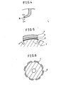
- the dimensions and shape of the core are: 92 mm outer diameter, 20 mm inner diameter, and 1.5 mm thickness. Eight slots of 3 mm width are grooved on the core.
- the core material is SPCC (mild steel), S50C (carbon steel) or SK-5 (tool steel) in JIS.
- the dimensions and shape of the segments are: 32 mm length, 2 mm thickness and 46 mm radius arc.
- the segment material is (1) sintered pure Co powder containing diamond grits or (2) double layer composite of sintered (Co + Cu) powder containing diamond grits and sintered Co powder without diamonds.
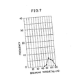
- the core was fixed and segments were broken by bending with a torque wrench and the torque required to break the segments was measured.
- segments brazed with Sil 103 solder by conventional process show strength of 40 - 110 kg.cm at room temperature, but the strength goes down with the temperature rise up to 250° - 350°C because of softening of the solder. At 350°C the strength goes down to less than 60 kg.cm for all segments.
- the melting point of Sil 103 is 620°C, and the chemical composition is: Ag 45.3%, Cu 15.6%, Cd 23.8% and Zn bal.
- Segments made of pure Co bond and a core made of SPCC were welded by an electron-beam. None of the welded areas were broken at 60 kg.cm torque, but the adjacent portions of the core were bent by the 60 kg.cm torque. This shows the welding strength is larger than the strength of the core material.
- the tempering process preferably at 350° - 450°C, is effective in eliminating brittleness of the heat-affected zone of the core (layer Z) and in increasing the strength of such easy-to-quench carbon-steel like SK-5 welded with the use of Ni-filler by an electron-beam.
- Fig. 4 shows the magnified trace of a molten zone produced by the electron-beam.
- the hatched area B is the molten zone.
- a and C show points neighboring the molten zone.
- D shows a distant point.
- the Micro-Vickers hardness was measured at these four points. The results are as follows: A: 332 B: 603 C: 358 D: 325
- Ni-filler With the combination of a pure Co bond segment, Ni-filler and SK-5 core, a homogeneous Ni-Co-Fe alloy is formed by electron-beam welding.
- the 33% Cu - 67% Co sintered powder compact is considered to be more likely to generate a metamorphosis of the material due to welding heat, because of the higher Cu content compared with the 15% Cu - 85% Co sintered powder compact, which relates to the problem of the Y-layer in Fig. 2.
- 100% Ni sheet filler and SPCC core samples of double layer segments having 0.5, 1 and 2 mm thick Co layers were prepared. The thickness of the Ni-filler was 0.2 mm.
- a Co base layer of at least 1 mm thickness prevents 33% Co - 67% Co sintered powder compact from becoming degenerated due to welding heat.
- Eight arc-shaped segments which were made of sintered (Co-Cu) powder with diamond grits, and whose dimensions were 2.0 mm thickness and 32 mm length, were brazed with ordinary solder on an SPCC (mild steel) circular disc whose dimensions were 92 mm outer diameter, 20 mm inner diameter and 1.5 mm thickness, by the use of a high frequency electric device. Distortion took place on the SPCC disc. The run-out of the distorted disc was measured at 70 mm diameter. The run-out fluctuated from +0.05 to -0.10 mm. This means the total distortion produced was 0.15 mm. Such a disc of 0.15 mm distortion cannot be employed in actual use at all.
- cutters composed of similar segments comprising CBN-grits instead of diamond-grits yield the same effects in the same manner.
- This invention is most suited to the segmented cutter blades mounted on handy or wagon-type portable machines which are used in cutting or working stones, concrete and slate.
Landscapes
- Engineering & Computer Science (AREA)
- Mechanical Engineering (AREA)
- Mining & Mineral Resources (AREA)
- Welding Or Cutting Using Electron Beams (AREA)
- Polishing Bodies And Polishing Tools (AREA)
Applications Claiming Priority (4)
| Application Number | Priority Date | Filing Date | Title |
|---|---|---|---|
| JP59092518A JPS60234776A (ja) | 1984-05-08 | 1984-05-08 | カツタ−セグメントの溶接方法 |
| JP6763584U JPS60178566U (ja) | 1984-05-08 | 1984-05-08 | カツタ− |
| JP67635/84U | 1984-05-08 | ||
| JP92518/84 | 1984-05-08 |
Publications (2)
| Publication Number | Publication Date |
|---|---|
| EP0163914A1 true EP0163914A1 (de) | 1985-12-11 |
| EP0163914B1 EP0163914B1 (de) | 1991-06-26 |
Family
ID=26408844
Family Applications (1)
| Application Number | Title | Priority Date | Filing Date |
|---|---|---|---|
| EP85105044A Expired EP0163914B1 (de) | 1984-05-08 | 1985-04-25 | Schweissmethode für Schneidsegmente |
Country Status (3)
| Country | Link |
|---|---|
| US (1) | US4689919A (de) |
| EP (1) | EP0163914B1 (de) |
| DE (1) | DE3583309D1 (de) |
Cited By (4)
| Publication number | Priority date | Publication date | Assignee | Title |
|---|---|---|---|---|
| EP0337753A3 (de) * | 1988-04-14 | 1991-05-08 | Blount, Inc. | Kettensäge zum Schneiden von granuliertem Material |
| WO1996003246A1 (de) * | 1994-07-27 | 1996-02-08 | Ledermann Gmbh | Werkzeug zur spanabhebenden bearbeitung und verfahren zu dessen herstellung |
| WO2007079980A3 (de) * | 2005-12-29 | 2007-11-01 | Boehler Uddeholm Prec Strip Gm | Bimetall-rakelklinge mit pulvermetallurgisch hergestellter arbeitskante |
| DE102006030661B4 (de) * | 2006-07-04 | 2009-02-05 | Profiroll Technologies Gmbh | Hartmetallisches Profilwalzwerkzeug |
Families Citing this family (12)
| Publication number | Priority date | Publication date | Assignee | Title |
|---|---|---|---|---|
| DE59707034D1 (de) * | 1996-11-15 | 2002-05-23 | Swarovski Tyrolit Schleif | Steintrennschleifwerkzeug mit Verbundträgerkörper |
| DE69904723T2 (de) * | 1999-10-14 | 2003-11-13 | Societe Anonyme Carbodiam, Tilly | Herstellungsverfahren einer Schleifscheibe |
| US6439327B1 (en) | 2000-08-24 | 2002-08-27 | Camco International (Uk) Limited | Cutting elements for rotary drill bits |
| PL3578299T3 (pl) * | 2008-08-08 | 2023-03-13 | Saint-Gobain Abrasives, Inc. | Wyroby ścierne |
| US9044841B2 (en) | 2008-11-19 | 2015-06-02 | Saint-Gobain Abrasives, Inc. | Abrasive articles and methods of forming |
| US9097067B2 (en) | 2009-02-12 | 2015-08-04 | Saint-Gobain Abrasives, Inc. | Abrasive tip for abrasive tool and method for forming and replacing thereof |
| CA2994435C (en) * | 2009-12-31 | 2020-04-14 | Saint-Gobain Abrasives, Inc. | Abrasive article incorporating an infiltrated abrasive segment |
| ES2806994T3 (es) | 2010-07-12 | 2021-02-19 | Saint Gobain Abrasives Inc | Artículo abrasivo para la conformación de materiales industriales |
| GB2540385B (en) * | 2015-07-15 | 2017-10-11 | C4 Carbides Ltd | Improvements in or relating to tool blades and their manufacture |
| EP3492193A4 (de) * | 2016-07-28 | 2019-10-02 | Hangzhou Great Star Tools Co., Ltd. | Schneidkomponente und herstellungsverfahren dafür |
| US10932402B2 (en) * | 2016-10-11 | 2021-03-02 | Deere & Company | Wear resistant disk blade and agricultural machine with wear resistant disk blade |
| CN107253290B (zh) * | 2017-07-17 | 2020-04-21 | 江苏锋泰工具有限公司 | 错齿排布金刚石锯片及其制备方法 |
Citations (6)
| Publication number | Priority date | Publication date | Assignee | Title |
|---|---|---|---|---|
| US3315548A (en) * | 1964-12-07 | 1967-04-25 | Contour Saws | Method of making band saw blade |
| US3593600A (en) * | 1969-04-29 | 1971-07-20 | Continental Can Co | Band saw blade apparatus and methods |
| US4144777A (en) * | 1976-09-28 | 1979-03-20 | Sandvik Aktiebolag | Circular saw blade and method for making the same |
| DE3238319A1 (de) * | 1981-10-15 | 1983-04-28 | Sumitomo Electric Industries, Ltd., Osaka | Verfahren zur herstellung von gebundenen hartlegierungen |
| EP0079243A1 (de) * | 1981-11-09 | 1983-05-18 | Sumitomo Electric Industries Limited | Kompaktverbundkörper der einen Presskörper aus Diamant oder Bornitrid enthält |
| US4407263A (en) * | 1981-03-27 | 1983-10-04 | Diamond Giken Co., Ltd. | Cutting blade |
Family Cites Families (6)
| Publication number | Priority date | Publication date | Assignee | Title |
|---|---|---|---|---|
| US2683923A (en) * | 1950-01-31 | 1954-07-20 | Universal Cyclops Steel Corp | Method of making composite metal products of fusion welded construction |
| US3069816A (en) * | 1959-04-22 | 1962-12-25 | Vanguard Abrasive Corp | Abrasive cut-off disks |
| US3203774A (en) * | 1959-05-08 | 1965-08-31 | Vanguard Abrasive Corp | Method of making an abrasive cut-off disk |
| US3110579A (en) * | 1960-01-04 | 1963-11-12 | Vanguard Abrasive Corp | Method of making a diamond abrasive saw blade |
| US3590535A (en) * | 1969-04-24 | 1971-07-06 | Federal Mogul Corp | Diamond abrasive saw blade |
| US4462293A (en) * | 1982-09-27 | 1984-07-31 | Gunzner Fred G | Wear-resistant and shock-resistant tools and method of manufacture thereof |
-
1985
- 1985-04-24 US US06/726,517 patent/US4689919A/en not_active Expired - Fee Related
- 1985-04-25 DE DE8585105044T patent/DE3583309D1/de not_active Expired - Fee Related
- 1985-04-25 EP EP85105044A patent/EP0163914B1/de not_active Expired
Patent Citations (6)
| Publication number | Priority date | Publication date | Assignee | Title |
|---|---|---|---|---|
| US3315548A (en) * | 1964-12-07 | 1967-04-25 | Contour Saws | Method of making band saw blade |
| US3593600A (en) * | 1969-04-29 | 1971-07-20 | Continental Can Co | Band saw blade apparatus and methods |
| US4144777A (en) * | 1976-09-28 | 1979-03-20 | Sandvik Aktiebolag | Circular saw blade and method for making the same |
| US4407263A (en) * | 1981-03-27 | 1983-10-04 | Diamond Giken Co., Ltd. | Cutting blade |
| DE3238319A1 (de) * | 1981-10-15 | 1983-04-28 | Sumitomo Electric Industries, Ltd., Osaka | Verfahren zur herstellung von gebundenen hartlegierungen |
| EP0079243A1 (de) * | 1981-11-09 | 1983-05-18 | Sumitomo Electric Industries Limited | Kompaktverbundkörper der einen Presskörper aus Diamant oder Bornitrid enthält |
Cited By (4)
| Publication number | Priority date | Publication date | Assignee | Title |
|---|---|---|---|---|
| EP0337753A3 (de) * | 1988-04-14 | 1991-05-08 | Blount, Inc. | Kettensäge zum Schneiden von granuliertem Material |
| WO1996003246A1 (de) * | 1994-07-27 | 1996-02-08 | Ledermann Gmbh | Werkzeug zur spanabhebenden bearbeitung und verfahren zu dessen herstellung |
| WO2007079980A3 (de) * | 2005-12-29 | 2007-11-01 | Boehler Uddeholm Prec Strip Gm | Bimetall-rakelklinge mit pulvermetallurgisch hergestellter arbeitskante |
| DE102006030661B4 (de) * | 2006-07-04 | 2009-02-05 | Profiroll Technologies Gmbh | Hartmetallisches Profilwalzwerkzeug |
Also Published As
| Publication number | Publication date |
|---|---|
| DE3583309D1 (de) | 1991-08-01 |
| US4689919A (en) | 1987-09-01 |
| EP0163914B1 (de) | 1991-06-26 |
Similar Documents
| Publication | Publication Date | Title |
|---|---|---|
| US4689919A (en) | Method for welding cutter segments | |
| CA1216158A (en) | Composite compact component and a process for the production of the same | |
| EP0106929B1 (de) | Verschleissfeste und stossfeste Werkzeuge und Verfahren für ihre Herstellung | |
| JPH09510148A (ja) | セグメント状に形成したダイヤモンドブレードの製造方法 | |
| US4144777A (en) | Circular saw blade and method for making the same | |
| CN109736712A (zh) | 激光焊接金刚石取芯钻头 | |
| US6541124B1 (en) | Drill resistant hard plate | |
| US4492846A (en) | Process for the production of bonded hard alloys | |
| US3719790A (en) | Composition and method for forming a weld-surfaced alloyed steel layer of steel | |
| US5265500A (en) | Method of making shock-resistant and wear-resistant tools of composite steel structure | |
| CN111922430A (zh) | 一种高抗弯强度激光焊接金刚石锯片的制备方法 | |
| JPH0324314B2 (de) | ||
| JPS62220294A (ja) | レ−ザ溶接法およびその装置 | |
| JPS6260204B2 (de) | ||
| CA1292875E (en) | High energy laser beam welded tools | |
| JPH052430B2 (de) | ||
| JPS5890385A (ja) | 複合耐摩部材の製造法 | |
| JPS6343788A (ja) | レ−ザ溶接方法 | |
| KR890000927B1 (ko) | 복합 내마모부재 및 그 제조법 | |
| GB2109730A (en) | Composite wear resisting member and the method for producing the same | |
| JPH05293641A (ja) | チタンカーバイト焼結合金とステンレス鋼との接合方法 | |
| Borisova et al. | Laser Welding of Diamond-Bearing Segments on Steel Frames[[Previously Titled: Laser Welding Diamond-Bearing Segments to Steel Holders.]] | |
| JP2000263451A (ja) | 切断用カッター及びその製造方法 | |
| JPS6343789A (ja) | 高密度エネルギ−ビ−ムによる溶融溶接法 | |
| JPS61244466A (ja) | 浸炭台金セグメントカツタ− |
Legal Events
| Date | Code | Title | Description |
|---|---|---|---|
| PUAI | Public reference made under article 153(3) epc to a published international application that has entered the european phase |
Free format text: ORIGINAL CODE: 0009012 |
|
| AK | Designated contracting states |
Designated state(s): DE FR GB IT |
|
| 17P | Request for examination filed |
Effective date: 19860206 |
|
| 17Q | First examination report despatched |
Effective date: 19870623 |
|
| GRAA | (expected) grant |
Free format text: ORIGINAL CODE: 0009210 |
|
| AK | Designated contracting states |
Kind code of ref document: B1 Designated state(s): DE FR GB IT |
|
| REF | Corresponds to: |
Ref document number: 3583309 Country of ref document: DE Date of ref document: 19910801 |
|
| ITF | It: translation for a ep patent filed | ||
| ET | Fr: translation filed | ||
| PLBE | No opposition filed within time limit |
Free format text: ORIGINAL CODE: 0009261 |
|
| STAA | Information on the status of an ep patent application or granted ep patent |
Free format text: STATUS: NO OPPOSITION FILED WITHIN TIME LIMIT |
|
| 26N | No opposition filed | ||
| PGFP | Annual fee paid to national office [announced via postgrant information from national office to epo] |
Ref country code: GB Payment date: 19970327 Year of fee payment: 13 |
|
| PGFP | Annual fee paid to national office [announced via postgrant information from national office to epo] |
Ref country code: FR Payment date: 19970417 Year of fee payment: 13 |
|
| PG25 | Lapsed in a contracting state [announced via postgrant information from national office to epo] |
Ref country code: GB Free format text: LAPSE BECAUSE OF NON-PAYMENT OF DUE FEES Effective date: 19980425 |
|
| PG25 | Lapsed in a contracting state [announced via postgrant information from national office to epo] |
Ref country code: FR Free format text: THE PATENT HAS BEEN ANNULLED BY A DECISION OF A NATIONAL AUTHORITY Effective date: 19980430 |
|
| PGFP | Annual fee paid to national office [announced via postgrant information from national office to epo] |
Ref country code: DE Payment date: 19980623 Year of fee payment: 14 |
|
| GBPC | Gb: european patent ceased through non-payment of renewal fee |
Effective date: 19980425 |
|
| REG | Reference to a national code |
Ref country code: FR Ref legal event code: ST |
|
| PG25 | Lapsed in a contracting state [announced via postgrant information from national office to epo] |
Ref country code: DE Free format text: LAPSE BECAUSE OF NON-PAYMENT OF DUE FEES Effective date: 20000201 |