EP0164553A1 - Boîte à vitesses multiples hydraulique-mécanique pour véhicules automobiles, contrôlable par un système hydraulique de soupapes - Google Patents
Boîte à vitesses multiples hydraulique-mécanique pour véhicules automobiles, contrôlable par un système hydraulique de soupapes Download PDFInfo
- Publication number
- EP0164553A1 EP0164553A1 EP85105357A EP85105357A EP0164553A1 EP 0164553 A1 EP0164553 A1 EP 0164553A1 EP 85105357 A EP85105357 A EP 85105357A EP 85105357 A EP85105357 A EP 85105357A EP 0164553 A1 EP0164553 A1 EP 0164553A1
- Authority
- EP
- European Patent Office
- Prior art keywords
- gear
- clutch
- brake
- shaft
- transmission
- Prior art date
- Legal status (The legal status is an assumption and is not a legal conclusion. Google has not performed a legal analysis and makes no representation as to the accuracy of the status listed.)
- Granted
Links
- 230000005540 biological transmission Effects 0.000 title claims abstract description 33
- 230000001970 hydrokinetic effect Effects 0.000 claims description 10
- 239000010687 lubricating oil Substances 0.000 claims description 8
- 239000003921 oil Substances 0.000 claims description 8
- 230000001419 dependent effect Effects 0.000 claims description 4
- 229910052751 metal Inorganic materials 0.000 claims description 3
- 239000002184 metal Substances 0.000 claims description 3
- 238000005096 rolling process Methods 0.000 claims description 3
- RTAQQCXQSZGOHL-UHFFFAOYSA-N Titanium Chemical compound [Ti] RTAQQCXQSZGOHL-UHFFFAOYSA-N 0.000 claims 1
- 239000010936 titanium Substances 0.000 claims 1
- 229910052719 titanium Inorganic materials 0.000 claims 1
- 238000011144 upstream manufacturing Methods 0.000 description 8
- 238000002485 combustion reaction Methods 0.000 description 3
- 230000008878 coupling Effects 0.000 description 3
- 238000010168 coupling process Methods 0.000 description 3
- 238000005859 coupling reaction Methods 0.000 description 3
- 238000003754 machining Methods 0.000 description 3
- 230000000694 effects Effects 0.000 description 2
- 230000000903 blocking effect Effects 0.000 description 1
- 238000006073 displacement reaction Methods 0.000 description 1
- 239000000446 fuel Substances 0.000 description 1
- 239000000314 lubricant Substances 0.000 description 1
- 238000005461 lubrication Methods 0.000 description 1
- 230000000717 retained effect Effects 0.000 description 1
- 238000004088 simulation Methods 0.000 description 1
Images


Classifications
-
- F—MECHANICAL ENGINEERING; LIGHTING; HEATING; WEAPONS; BLASTING
- F16—ENGINEERING ELEMENTS AND UNITS; GENERAL MEASURES FOR PRODUCING AND MAINTAINING EFFECTIVE FUNCTIONING OF MACHINES OR INSTALLATIONS; THERMAL INSULATION IN GENERAL
- F16H—GEARING
- F16H63/00—Control outputs from the control unit to change-speed- or reversing-gearings for conveying rotary motion or to other devices than the final output mechanism
- F16H63/02—Final output mechanisms therefor; Actuating means for the final output mechanisms
- F16H63/30—Constructional features of the final output mechanisms
- F16H63/3003—Band brake actuating mechanisms
-
- F—MECHANICAL ENGINEERING; LIGHTING; HEATING; WEAPONS; BLASTING
- F16—ENGINEERING ELEMENTS AND UNITS; GENERAL MEASURES FOR PRODUCING AND MAINTAINING EFFECTIVE FUNCTIONING OF MACHINES OR INSTALLATIONS; THERMAL INSULATION IN GENERAL
- F16H—GEARING
- F16H3/00—Toothed gearings for conveying rotary motion with variable gear ratio or for reversing rotary motion
- F16H3/44—Toothed gearings for conveying rotary motion with variable gear ratio or for reversing rotary motion using gears having orbital motion
- F16H3/62—Gearings having three or more central gears
- F16H3/66—Gearings having three or more central gears composed of a number of gear trains without drive passing from one train to another
-
- F—MECHANICAL ENGINEERING; LIGHTING; HEATING; WEAPONS; BLASTING
- F16—ENGINEERING ELEMENTS AND UNITS; GENERAL MEASURES FOR PRODUCING AND MAINTAINING EFFECTIVE FUNCTIONING OF MACHINES OR INSTALLATIONS; THERMAL INSULATION IN GENERAL
- F16H—GEARING
- F16H2200/00—Transmissions for multiple ratios
- F16H2200/003—Transmissions for multiple ratios characterised by the number of forward speeds
- F16H2200/0043—Transmissions for multiple ratios characterised by the number of forward speeds the gear ratios comprising four forward speeds
Definitions
- the invention is based on a multi-speed, hydrokinetic-mechanical change gear for motor vehicles, which can be switched via a hydraulic control valve system, of the type explained in the preamble of claim 1.
- a multi-speed, hydrokinetic-mechanical change gear for motor vehicles is already known, in which, starting from a given multi-speed change gear, consisting of a hydrokinetic torque converter and a planetary gear change gear in the form of a so-called Simpson set , which normally provides three forward gears and one reverse gear, while maintaining essential parts of the transmission, a four forward gears and one reverse gear transmission is provided by connecting a simple planetary gear set with a clutch and brake assembly controlling them.
- the transmission is here provided between its input and its output shaft with a center shaft, such that the turbine shaft forming the drive shaft of the transmission is drivingly connected to the ring gear of the upstream planetary gear set, the sun wheel of which is drivingly connected via a connecting part to a brake drum, on the latter Attack on the outside of a brake band and on the inside of a multi-plate clutch, so that either the sun gear is fixed via the brake band or can be connected to the ring gear via the multi-plate clutch and the planet gear carrier of the upstream planetary gear set is drivingly connected to the center shaft.
- the center shaft is connected to a coupling body which forms the input element of the Simpson set.
- the upstream planetary gear set is locked and, in conjunction with the likewise locked Simpson set, provides a 1: 1 translation of a direct forward gear.
- the given gear is designed in the form of a hydrokinetic torque converter and a planetary gear set in the form of a Simpsom set for internal combustion engines of a certain power class between 1.8 1 to 2.8 1 cubic capacity or 55-110 kW the retained components are undoubtedly somewhat oversized for the engines of the lower performance class.
- the object of the invention is, similar to the known transmission, starting from a given transmission with a hydrokinetic torque converter and a planetary gear in the form of a Simpson set, while maintaining essential components by connecting a simple planetary gear set to four forward gears and to create a reverse gear extended transmission, but the fourth forward gear is designed as a gentle gear to achieve fuel savings.
- a hydrokinetic torque converter known per se with a lock-up clutch is used in this context, so that any slip in the converter can be avoided in the third and fourth forward gears above certain speeds.
- Another part of the object of the invention is to improve the efficiency of the extended transmission so that the pressure medium pump present in the given transmission with a small power requirement can also be maintained for the extended transmission without thereby causing difficulties in the supply of the torque converter or extended gearbox with pressure medium and lubricant occur.
- this object is achieved in that the features indicated in the characterizing part of the claim and the measures explained in claims 2 to 5 are applied to a transmission according to the preamble of claim 1.
- the turbine shaft forming the drive shaft of the transmission is serrated connected to the planet gear carrier, the sun gear of which is serrated via a connecting part with a brake drum, on the outside of which a brake band and on the inside of which a multi-plate clutch engages, the sun wheel being fixable via the brake band is and via the multi-plate clutch, the sun gear can be connected to the planet gear carrier to lock the planetary gear set and the ring gear is splined to the center shaft, which is splined again to the input member, the coupling body, the Simpson set and additionally between a cup-shaped part of the Center shaft and the hub of the planet carrier an overrunning clutch is arranged, in shift position "D" for 1st, 2nd and 3rd gear and reverse gear locking of the upstream gentle gear planetary gear set in the direction of rotation is ensured without this hydraulic servo device would have to be operated.
- the multi-plate clutch provided between the sun gear and the planet gear carrier is only actuated when an engine braking effect is required for pushing operation when driving downhill and the brake band engaging the brake drum connected to the sun gear is actuated only via a servo when the gentle gear in driving range "D" is switched on becomes.
- the hydrokinetic torque converter provided with a converter lock-up clutch can be engaged both in the 3rd and in the 4th forward gear depending on the speed and load, and the control of the converter lock-up clutch takes place via two switchable pressure medium circuits via channels formed between the drive shaft and a housing-mounted hob lift , the one of the channels running over radial and axial bores in the stator hub and across the area of the roller arrangement of the overrunning clutch of the stator, the provision of larger, lower pressure losses causing flow channels is achieved.
- bearing points of the change gearbox are partially provided with needle bearings in a known manner and are supplied via a front, middle and rear lubricating oil channel system, with a branch channel of the middle skid oil channel acting on the roller area of the first overrunning clutch and an oil baffle disc throttling the outflow of the selnder oil, which the rolling elements float in freewheel mode, friction losses in the higher gears are reduced to a minimum.
- receptacles for electromechanical pressure transmitter units are provided in the control valve housing, which, by their subsequent use, enable the simulation of the pressure signals essential for the hydraulic control valve system, the throttle pressure and the regulator pressure electronically from a microprocessor, further reduce the need for pressure medium in the transmission.
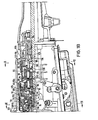
- one end of the crankshaft of an internal combustion engine is designated by 10. It is connected by screws 11 to the center of a drive plate 12, the edge of which is fastened by nuts 13 to screw bolts 14 on the drive jacket 16 of a hydrokinetic torque converter 18.
- the hydrokinetic torque converter 18 consists in a known manner of a pump part 20, a turbine part 22 and a guide part 26, which are arranged in an annular flow circuit.
- the guide part 26 is supported in the usual way via a hub 28 on a fixed hollow hub 30 via an upper coupling 32.
- the turbine part 22 is connected via a turbine hub 34 to a turbine shaft 36, which forms the input shaft of the transmission.
- the pump part 20 is supported via a pump hub 38 in a bearing opening 40 in a transverse wall 42 which forms part of the housing 44 of the torque converter.
- a transmission housing 46 is connected to the torque converter housing 44 via screws 48.
- a pump housing 50 is connected to the transverse wall 42 and is made in one piece with the fixed hollow hub 30.
- the pump housing 50 contains gear wheels 52 of a displacement pump, which provides the pressure medium for the hydraulic control valve system.
- the pump housing 50 also has a bearing part 54, on which a brake drum 56 is rotatably mounted, which receives an annular cylinder 58 and an annular piston 60.
- the cylinder 58 can be pressurized via a channel 62 in the bearing part 54.
- the cylinder 58 and the piston 60 form the actuation servo for a first multi-plate clutch 64 / CL 1 .
- the brake drum 56 is enclosed by a brake band 57 and forms a first brake B 1 .
- An upstream, simple planetary gear set 66 consists of a planet gear carrier 68 drivingly connected to the turbine shaft 36, welded from two sheet metal pressed parts, one via a separate connecting part 72 and a ring gear, which engages on the one hand with internal teeth on the sun gear 70 and on the other hand with external teeth on the brake drum 56 74, which is directly splined to the center shaft 76.
- the planetary gear set 66 can be locked by engaging the first clutch CL 1 , which connects the planet gear carrier 68 with the sun gear 70, in order to achieve an engine braking effect in the switching positions "1, 2, 3, and R". Furthermore, the planetary gear set 66 is locked in the drive direction of rotation of the ring gear by an upper hot clutch 77 / OWC 1 , which is arranged between a shoulder on the central shaft 76 and an inner race 69 connected to the planet gear carrier 68 and is effective in the switching position "D".
- the Ptanetenradsatz 66 is effective by applying the brake band 57 / B 1 as a reduction gear to provide the gentle gear.
- a transverse wall 78 is arranged in the gear housing 46 and is fixed in position on one side by a shoulder 80 and on the other side by a snap ring 82.
- the transverse wall 78 is provided with supply channels 79 for distributing the pressure medium
- the transverse wall 78 separates the gentle gear planetary gear set 66 from a second transmission part within the transmission housing 46, in which a second and a third planetary gear set 84 and 86 are arranged.
- the planetary gear set 84 consists of a ring gear 88, a sun gear 90, a planet gear carrier 92 with planet gears arranged thereon, the planet gear carrier 92 being splined directly to the output shaft 94 of the transmission.
- the planetary gear set 86 consists of a ring gear 96, a planet gear carrier 98 with planet gears arranged thereon and a sun gear 90 which forms a component with the sun gear of the set 84.
- the planet gear carrier 98 is drivingly connected to a brake drum 100, which is enclosed by a brake band 102 and forms a third brake B S.
- the brake drum 100 is supported via an overrunning clutch 110 on a fixed inner race 104, which is received in a rotationally fixed manner on a projection 106 of the end wall 108 of the transmission housing.
- the center shaft 76 is connected directly to a clutch body 112 which forms the input element of the Simpson set and which carries clutch disks for a second and third multi-plate clutch 114 / CL Z and 116 / CL 3 .
- Clutch disks that are connected to the ring gear 88 interact with the clutch disks on the clutch body 112 and enable a driving connection between the clutch body 112 and the ring gear 88.
- the multi-plate clutch 114 / CL 2 consists of clutch disks which are carried by the clutch body 112 and clutch disks which are carried by a brake drum 118 which is connected via a drive bell 130 to the common sun gear 90 of the two planetary gear sets.
- the clutch disks on the clutch body 112 interact with the clutch disks on the brake drum 118 and enable a driving connection between the clutch body 112 and the common sun gear 90.
- the clutch disks of the multi-plate clutch 114 / CL 2 can be pressed against one another by a piston 120 which is arranged in a cylinder 122 in the brake drum 118.
- the clutch disks of the multi-plate clutch 116 / CL 3 are pressed against one another via a piston 124, which is arranged in an annular cylinder 126 in the clutch body 112.
- a brake band 128 comprises the brake drum 118 and forms a second brake B 2 , by means of which the common sun gear 90 of the two planetary gear sets connected via the drive bell 123 can be fixed.
- the first planetary gear set 66 When the manual shift lever is inserted into the shift positions "1, 2 or R", the first planetary gear set 66 is locked during operation in the two lower forward gears and in reverse gear, namely in the first and second forward gears and in reverse gear through the engaged first clutch CL 1 as also thanks to the effective first overbolt clutch OWC 1 .
- the drive torque is therefore transmitted from the turbine shaft via the locked upstream planetary gear set to the center shaft and from there to the input member of the Simpson set, both in the pulling and pushing directions.
- the Simpson set is driven via the engaged third clutch CL 3 , the planet gear carrier of the third set being fixed via the third brake B 3 and / or the overrunning clutch 100 / OWC 2 .
- the drive of the Simpson set remains upright via the third clutch CL 3 and instead of the planet carrier of the third set, the sun gear 90 is fixed via the second brake B 2 .
- the second clutch CL 2 is engaged and the second brake B 2 is released , which locks the second planetary gear set and achieves a 1: 1 direct gear ratio in connection with the likewise locked upstream planetary gear set becomes.
- the first brake B 1 is actuated, whereby the sun gear of the first set is fixed.
- the ring gear of the first set is driven at a geared speed and the first overrunning clutch OWC 1 is released.
- the Simpson set remains locked due to the two clutches CL 2 and CL 3 engaged.
- the first planetary gear set like in 1st gear, is locked by the first clutch CL 1 or the overrunning clutch 77 / OWC 1 .
- the Simpson set is driven via the second clutch CL 2 , the planet gear carrier of the third set being defined via the third brake B 3 .
- the hydrokinetic torque converter 18 is provided between the drive jacket 16 and the turbine and clutch hub 34 with a torque converter lock-up clutch 140 / LUC, which in a known manner consists of a clutch disc 142 in connection with a damper arrangement 144.
- the torque converter lock-up clutch 140 / LUC can be engaged and disengaged via two switchable pressure medium circuits, which are formed via an annular channel 37 formed between the drive shaft 36 and the hollow hub 30 fixed to the housing or an annular channel formed between the hollow hub 30 and the pump hub 38 designed as a hollow shaft Channel 31 are applied.
- One channel 31 runs over radial bores 33 in the stator hub 28, whereby it flows transversely through the area of the roller arrangement of the stator overrunning clutch 32 and thereby ensures larger flow cross-sections on the one hand and on the other hand reduces the friction losses in the freewheeling operation of the overrunning clutch by floating the roller bodies .
- a large number of bearing points of the change gearbox are provided with needle bearings in a manner known per se and are accordingly supplied with harmful oil via a front, middle and rear lubrication oil duct system 150, 160 and 170.
- the front lubricating oil channel system 150 primarily supplies the bearings 152 of the gentle clutch and brake trowel 56 to 64, the thrust washers 154 of the provisional gear 66 as well as the axial support of the planet gear carrier 68 via a needle bearing 156.
- a branch channel 162 of the central lubricating oil channel system 160 supplies the Roller area of the first overrunning clutch 77 / OWC 1, an oil blocking disk 164 being arranged on the opposite side of the overrunning clutch in such a way that the outflow of the lubricating oil is throttled in such a way that the rolling elements can float in freewheel mode and the friction loss is thereby considerably reduced.
- a branch passage 166 primarily feeds the bearing 168 of the clutch cylinder brake drum assembly of the forward clutch 114 to 122.
- the rear Schzmer oil duct system 170 supplies the bearing of the common sun gear 90 of the Simpson planetary gear set, the planet gears of the Simpson planetary gear set and the bearing 178 of the output shaft 94 and the rear overrunning clutch 110 via branch channels 172, 174 and 176.
- the brake band 57 of the first brake B 1 is actuated by a servo 180, which is relatively small in volume, via an actuating lever 182 that enables a power transmission.
- the brake band 128 / B 2 which is provided for fixing the common sun gear 90 of the Simpson planetary gear set, is also actuated by a relatively small volume servo 190 via an actuating lever 192 that enables a power transmission.
- This actuating lever 192 is located in the gear housing 46 further back as seen from the machining side and the bores in the gear housing required for receiving its pivot bolt 194 can only be produced if access is kept free from the machining side.
- the operating lever 182 arranged further forward in the gear housing 46 with its pivot bolt 184 is arranged in a substantially U-shaped bearing block 186 stamped from sheet metal, which is only after machining the receptacle for the bolt 194 in the gear housing 46 provided receiving pocket 188 is inserted.
- the brake band 102 / BS is actuated by a slightly larger servo 200, which is arranged vertically lying to keep the gearbox narrow at the side.
- line ducts can be prepared in order to lead line pressure ducts and signal pressure ducts to a valve bore into which externally electromagnetically controlled pressure transducer valves can be used in order to electrohydraulically display the torque-dependent throttle pressure signal and the speed-dependent regulator pressure signal instead of the usual hydraulic display using a microprocessor.
- the usual throttle pressure valve connected to the throttle valve via a linkage and the regulator pressure valve arranged on a part connected to the output shaft can be dispensed with.
Landscapes
- Engineering & Computer Science (AREA)
- General Engineering & Computer Science (AREA)
- Mechanical Engineering (AREA)
- Structure Of Transmissions (AREA)
Applications Claiming Priority (2)
| Application Number | Priority Date | Filing Date | Title |
|---|---|---|---|
| DE3417703 | 1984-05-12 | ||
| DE3417703A DE3417703C2 (de) | 1984-05-12 | 1984-05-12 | Mehrgängiges, über ein hydraulisches Steuerventilsystem schaltbares hydrokinetisch - mechanisches Wechselgetriebe für Kraftfahrzeuge |
Publications (2)
| Publication Number | Publication Date |
|---|---|
| EP0164553A1 true EP0164553A1 (fr) | 1985-12-18 |
| EP0164553B1 EP0164553B1 (fr) | 1988-07-06 |
Family
ID=6235693
Family Applications (1)
| Application Number | Title | Priority Date | Filing Date |
|---|---|---|---|
| EP85105357A Expired EP0164553B1 (fr) | 1984-05-12 | 1985-05-02 | Boîte à vitesses multiples hydraulique-mécanique pour véhicules automobiles, contrôlable par un système hydraulique de soupapes |
Country Status (4)
| Country | Link |
|---|---|
| US (1) | US4649763A (fr) |
| EP (1) | EP0164553B1 (fr) |
| JP (1) | JPS60249770A (fr) |
| DE (2) | DE3417703C2 (fr) |
Cited By (6)
| Publication number | Priority date | Publication date | Assignee | Title |
|---|---|---|---|---|
| EP0162352B1 (fr) * | 1984-05-14 | 1988-07-06 | Ford-Werke Aktiengesellschaft | Système hydraulique de valves de contrôle pour une boîte de vitesses automatique hydrocinétique-mécanique pour véhicules automobiles |
| EP0253380A3 (en) * | 1986-07-15 | 1989-02-22 | Ford-Werke Aktiengesellschaft | Planetary gear box of the simpson-set type |
| EP0381540A3 (en) * | 1989-02-03 | 1990-12-05 | Toyota Jidosha Kabushiki Kaisha | Automatic transmission |
| US5057063A (en) * | 1989-03-15 | 1991-10-15 | Toyota Jidosha Kabushiki Kaisha | Automatic transmission |
| US5090952A (en) * | 1989-02-03 | 1992-02-25 | Toyota Jidosha Kabushiki Kaisha | Automatic transmission |
| US5120284A (en) * | 1989-02-03 | 1992-06-09 | Toyota Jidosha Kabushiki Kaisha | Automatic transmission |
Families Citing this family (12)
| Publication number | Priority date | Publication date | Assignee | Title |
|---|---|---|---|---|
| DE3447938A1 (de) * | 1984-05-14 | 1985-11-14 | Ford-Werke AG, 5000 Köln | Hydraulisches steuerventilsystem fuer ein mehrgaengiges, selbsttaetig schaltendes, hydrokinetisch-mechanisches wechselgetriebe fuer kraftfahrzeuge |
| DE3608507A1 (de) * | 1986-03-14 | 1987-09-24 | Ford Werke Ag | Radial-axial-gleitlager, insbesondere fuer automatik-getriebe von kraftfahrzeugen |
| DE3612046A1 (de) * | 1986-04-10 | 1987-10-15 | Ford Werke Ag | Rollen- oder klemmkoerper-freilauf, insbesondere fuer automatik-getriebe fuer kraftfahrzeuge |
| US4884471A (en) * | 1988-06-23 | 1989-12-05 | Ford Motor Company | Four speed ratio automatic power transmission |
| WO1991005184A1 (fr) * | 1989-09-27 | 1991-04-18 | Ford Motor Company Limited | Commande de surmultiplication pour transmission hydrocinetique |
| DE4301493C2 (de) * | 1993-01-21 | 1995-09-14 | Ford Werke Ag | Lageranordnung und Abdichtung für die Wandlernabe eines hydrokinetisch-mechanischen Automatik-Getriebes für Kraftfahrzeuge |
| DE4420959B4 (de) | 1993-07-09 | 2006-05-11 | Luk Gs Verwaltungs Kg | Hydrodynamischer Strömungswandler |
| US5782327A (en) * | 1993-07-09 | 1998-07-21 | Luk Getriebe-Systeme Gmbh | Hydrokinetic torque converter and lockup clutch therefor |
| DE19544089C1 (de) * | 1995-11-27 | 1997-05-28 | Ford Werke Ag | Hydraulische Servo-Vorrichtung für eine Reibungsbremse in einem Planetenräder-Wechselgetriebe für Kraftfahrzeuge |
| US5711403A (en) * | 1996-11-04 | 1998-01-27 | Ford Global Technologies, Inc. | Rapid apply servo for a brake band of an automatic transmission |
| CN1327148C (zh) * | 2004-02-20 | 2007-07-18 | 吉林大学 | 具有双离合器的液力变矩器 |
| DE102017203766A1 (de) | 2017-03-08 | 2018-09-13 | Zf Friedrichshafen Ag | Lageranordnung zur Radialkraftabstützung in einem Getriebe |
Citations (10)
| Publication number | Priority date | Publication date | Assignee | Title |
|---|---|---|---|---|
| US2829542A (en) * | 1954-09-20 | 1958-04-08 | Borg Warner | Transmission |
| US3073179A (en) * | 1953-12-04 | 1963-01-15 | Gen Motors Corp | Torque transmitting mechanism |
| DE2227555A1 (de) * | 1971-06-17 | 1972-12-21 | Ford Werke AG, 5000 Köln | Planetenrader Wechselgetriebe mit hydraulischem Steuervenülsystem, ins besondere fur Kraftfahrzeuge |
| FR2143813A1 (fr) * | 1971-06-28 | 1973-02-09 | Gen Motors Corp | |
| FR2366495A1 (fr) * | 1976-09-29 | 1978-04-28 | Pont A Mousson | Mecanisme de transmission pour vehicules automobiles |
| DE2821008A1 (de) * | 1977-05-13 | 1978-12-07 | Nissan Motor | Gangschaltgetriebe |
| GB1554190A (en) * | 1976-05-24 | 1979-10-17 | Variabe Kinetic Drives Ltd | Power transmission apparatus |
| GB2067688A (en) * | 1980-01-22 | 1981-07-30 | Aisin Warner | Automatic transmission including torque converter with lock-up clutch |
| EP0072084A2 (fr) * | 1981-07-21 | 1983-02-16 | Toyota Jidosha Kabushiki Kaisha | Dispositif et méthode pour commander de manière précise une transmission automatique avec embrayage "court-circuit" |
| US4382393A (en) * | 1980-04-21 | 1983-05-10 | Trans Auto Specialties, Inc. | Retrofittable overdrive assembly |
Family Cites Families (15)
| Publication number | Priority date | Publication date | Assignee | Title |
|---|---|---|---|---|
| GB415215A (en) | 1933-05-02 | 1934-08-23 | Compressed Rubber Products Ltd | Improvements in or relating to brackets for stationary or swivelling castors or the like |
| GB717111A (en) * | 1947-05-16 | 1954-10-20 | Clifton Ross Roche | Improvements in or relating to change-speed power transmission |
| US2737423A (en) | 1951-05-31 | 1956-03-06 | Borg Warner | Mounting assembly for relatively rotatable members |
| US3252352A (en) * | 1963-02-18 | 1966-05-24 | Ford Motor Co | Hydrokinetic power transmitting mechanism |
| US3463033A (en) | 1968-02-20 | 1969-08-26 | Ford Motor Co | Multiple ratio hydrokinetic torque converter transmission with split-torque lock-up clutches in the converter housing |
| US3584520A (en) * | 1969-11-28 | 1971-06-15 | Gen Motors Corp | Transmission |
| US3602055A (en) * | 1970-03-02 | 1971-08-31 | Gen Motors Corp | Transmission |
| JPS53123765A (en) * | 1977-04-05 | 1978-10-28 | Toyota Motor Corp | Overdrive device for automatic speed change gear |
| JPS53134165A (en) * | 1977-04-27 | 1978-11-22 | Toyota Motor Corp | Automatic transmission gear box |
| JPS54145859A (en) * | 1978-05-04 | 1979-11-14 | Aisin Warner | Automatic transmission with overdrive |
| JPS5635845A (en) * | 1979-08-30 | 1981-04-08 | Aisin Warner Ltd | Overdrive device in automatic speed change gear |
| US4400998A (en) * | 1980-05-12 | 1983-08-30 | Ford Motor Company | Four speed overdrive transaxle |
| US4368649A (en) * | 1980-07-01 | 1983-01-18 | Ford Motor Company | Automatic transaxle driveline having four forward driving ratios and a single reverse ratio |
| JPS57167529A (en) * | 1981-04-08 | 1982-10-15 | Aisin Seiki Co Ltd | Control system for torque convertor equipped with direct connection clutch |
| JPS58196351A (ja) * | 1982-05-12 | 1983-11-15 | Nissan Motor Co Ltd | オ−バ−ドライブ機構付自動変速機 |
-
1984
- 1984-05-12 DE DE3417703A patent/DE3417703C2/de not_active Expired
-
1985
- 1985-05-02 DE DE8585105357T patent/DE3563648D1/de not_active Expired
- 1985-05-02 EP EP85105357A patent/EP0164553B1/fr not_active Expired
- 1985-05-08 US US06/732,026 patent/US4649763A/en not_active Expired - Lifetime
- 1985-05-13 JP JP60101175A patent/JPS60249770A/ja active Granted
Patent Citations (10)
| Publication number | Priority date | Publication date | Assignee | Title |
|---|---|---|---|---|
| US3073179A (en) * | 1953-12-04 | 1963-01-15 | Gen Motors Corp | Torque transmitting mechanism |
| US2829542A (en) * | 1954-09-20 | 1958-04-08 | Borg Warner | Transmission |
| DE2227555A1 (de) * | 1971-06-17 | 1972-12-21 | Ford Werke AG, 5000 Köln | Planetenrader Wechselgetriebe mit hydraulischem Steuervenülsystem, ins besondere fur Kraftfahrzeuge |
| FR2143813A1 (fr) * | 1971-06-28 | 1973-02-09 | Gen Motors Corp | |
| GB1554190A (en) * | 1976-05-24 | 1979-10-17 | Variabe Kinetic Drives Ltd | Power transmission apparatus |
| FR2366495A1 (fr) * | 1976-09-29 | 1978-04-28 | Pont A Mousson | Mecanisme de transmission pour vehicules automobiles |
| DE2821008A1 (de) * | 1977-05-13 | 1978-12-07 | Nissan Motor | Gangschaltgetriebe |
| GB2067688A (en) * | 1980-01-22 | 1981-07-30 | Aisin Warner | Automatic transmission including torque converter with lock-up clutch |
| US4382393A (en) * | 1980-04-21 | 1983-05-10 | Trans Auto Specialties, Inc. | Retrofittable overdrive assembly |
| EP0072084A2 (fr) * | 1981-07-21 | 1983-02-16 | Toyota Jidosha Kabushiki Kaisha | Dispositif et méthode pour commander de manière précise une transmission automatique avec embrayage "court-circuit" |
Cited By (7)
| Publication number | Priority date | Publication date | Assignee | Title |
|---|---|---|---|---|
| EP0162352B1 (fr) * | 1984-05-14 | 1988-07-06 | Ford-Werke Aktiengesellschaft | Système hydraulique de valves de contrôle pour une boîte de vitesses automatique hydrocinétique-mécanique pour véhicules automobiles |
| EP0253380A3 (en) * | 1986-07-15 | 1989-02-22 | Ford-Werke Aktiengesellschaft | Planetary gear box of the simpson-set type |
| EP0381540A3 (en) * | 1989-02-03 | 1990-12-05 | Toyota Jidosha Kabushiki Kaisha | Automatic transmission |
| US5083992A (en) * | 1989-02-03 | 1992-01-28 | Toyota Jidosha Kabushiki Kaisha | Automatic transmission |
| US5090952A (en) * | 1989-02-03 | 1992-02-25 | Toyota Jidosha Kabushiki Kaisha | Automatic transmission |
| US5120284A (en) * | 1989-02-03 | 1992-06-09 | Toyota Jidosha Kabushiki Kaisha | Automatic transmission |
| US5057063A (en) * | 1989-03-15 | 1991-10-15 | Toyota Jidosha Kabushiki Kaisha | Automatic transmission |
Also Published As
| Publication number | Publication date |
|---|---|
| DE3417703A1 (de) | 1985-11-14 |
| US4649763A (en) | 1987-03-17 |
| DE3417703C2 (de) | 1987-01-02 |
| EP0164553B1 (fr) | 1988-07-06 |
| JPH0448980B2 (fr) | 1992-08-10 |
| DE3563648D1 (en) | 1988-08-11 |
| JPS60249770A (ja) | 1985-12-10 |
Similar Documents
| Publication | Publication Date | Title |
|---|---|---|
| DE69301757T2 (de) | Mehrgängiges, synchron-automatisches Getriebe für Kraftfahrzeuge | |
| EP0164553B1 (fr) | Boîte à vitesses multiples hydraulique-mécanique pour véhicules automobiles, contrôlable par un système hydraulique de soupapes | |
| DE69005958T2 (de) | Quermontiertes automatisches Getriebe für eine Fahrzeugkraftübertragung. | |
| DE4432889C2 (de) | Kraftfahrzeug mit stufenlosem Getriebe | |
| DE69405196T2 (de) | Hydraulisches steuersystem für automatische fahrzeuggetriebe | |
| DE4405048A1 (de) | Automatisch schaltbares Stufenwechselgetriebe mit drei Planetensätzen | |
| DE3709191A1 (de) | Stufenloses verzweigungsgetriebe insbesondere fuer kraftfahrzeuge | |
| DE2621447A1 (de) | Schaltbare kraftuebertragungseinrichtung fuer motorfahrzeuge | |
| DE2203501A1 (de) | Planetenraeder-Wechselgetriebe mit hydraulischem Steuerventilsystem,insbesondere fuer Kraftfahrzeuge | |
| DE19513276B4 (de) | Antriebsstrang für automatische Kraftübertragung bei einem Kraftfahrzeug | |
| DE19530486A1 (de) | Automatikgetriebe-Kraftübertragungsstrang für ein Fahrzeug | |
| DE2943451A1 (de) | Wechselgetriebe fuer kraftfahrzeuge | |
| DE69308490T2 (de) | Mehrgängiges Automatikgetriebe für Kraftfahrzeuge | |
| EP0162352B1 (fr) | Système hydraulique de valves de contrôle pour une boîte de vitesses automatique hydrocinétique-mécanique pour véhicules automobiles | |
| DE3026773A1 (de) | Getriebe mit einem hydraulischen retarder | |
| DE4116233C2 (de) | System zur Kraftübertragung von einer Brennkraftmaschine auf die Vorder- und Hinterräder eines Kraftfahrzeugs | |
| EP1319867A2 (fr) | Dispositif de démarrage de véhicule équipé d'une boíte automatique | |
| DE68922291T2 (de) | Automatisches Wechselgetriebe mit einer zusätzlichen Getriebestufe. | |
| DE3906338A1 (de) | Hydraulische steuervorrichtung fuer ein automatisches getriebe | |
| DE1455685A1 (de) | Hydrodynamische Bremse | |
| DE69210137T2 (de) | Leistungsübertragungseinrichtung mit T-förmiger Anordnung | |
| DE3910410A1 (de) | Hydrostatisch mechanisches leistungsverzweigungsgetriebe | |
| DE1630864A1 (de) | Selbsttaetig schaltender Steuerapparat fuer automatische Wechselgetriebe in Automobilen | |
| DE3447941C2 (de) | Hydrokinetisch-mechanisches Wechselgetriebe für Kraftfahrzeuge | |
| DE3906269A1 (de) | Hydraulische steuervorrichtung fuer ein automatisches getriebe |
Legal Events
| Date | Code | Title | Description |
|---|---|---|---|
| PUAI | Public reference made under article 153(3) epc to a published international application that has entered the european phase |
Free format text: ORIGINAL CODE: 0009012 |
|
| AK | Designated contracting states |
Designated state(s): BE DE FR GB IT NL SE |
|
| 17P | Request for examination filed |
Effective date: 19851031 |
|
| 17Q | First examination report despatched |
Effective date: 19870129 |
|
| GRAA | (expected) grant |
Free format text: ORIGINAL CODE: 0009210 |
|
| AK | Designated contracting states |
Kind code of ref document: B1 Designated state(s): BE DE FR GB IT NL SE |
|
| REF | Corresponds to: |
Ref document number: 3563648 Country of ref document: DE Date of ref document: 19880811 |
|
| ITF | It: translation for a ep patent filed | ||
| ET | Fr: translation filed | ||
| GBT | Gb: translation of ep patent filed (gb section 77(6)(a)/1977) | ||
| PLBE | No opposition filed within time limit |
Free format text: ORIGINAL CODE: 0009261 |
|
| STAA | Information on the status of an ep patent application or granted ep patent |
Free format text: STATUS: NO OPPOSITION FILED WITHIN TIME LIMIT |
|
| 26N | No opposition filed | ||
| PGFP | Annual fee paid to national office [announced via postgrant information from national office to epo] |
Ref country code: DE Payment date: 19900510 Year of fee payment: 6 |
|
| PG25 | Lapsed in a contracting state [announced via postgrant information from national office to epo] |
Ref country code: DE Effective date: 19910419 |
|
| REG | Reference to a national code |
Ref country code: GB Ref legal event code: 746 Effective date: 19930422 |
|
| REG | Reference to a national code |
Ref country code: FR Ref legal event code: DL |
|
| ITTA | It: last paid annual fee | ||
| EAL | Se: european patent in force in sweden |
Ref document number: 85105357.9 |
|
| REG | Reference to a national code |
Ref country code: FR Ref legal event code: TP Ref country code: FR Ref legal event code: CD |
|
| PGFP | Annual fee paid to national office [announced via postgrant information from national office to epo] |
Ref country code: SE Payment date: 20010503 Year of fee payment: 17 |
|
| PGFP | Annual fee paid to national office [announced via postgrant information from national office to epo] |
Ref country code: GB Payment date: 20010508 Year of fee payment: 17 |
|
| PGFP | Annual fee paid to national office [announced via postgrant information from national office to epo] |
Ref country code: NL Payment date: 20010509 Year of fee payment: 17 |
|
| PGFP | Annual fee paid to national office [announced via postgrant information from national office to epo] |
Ref country code: FR Payment date: 20010511 Year of fee payment: 17 |
|
| PGFP | Annual fee paid to national office [announced via postgrant information from national office to epo] |
Ref country code: BE Payment date: 20010514 Year of fee payment: 17 |
|
| REG | Reference to a national code |
Ref country code: GB Ref legal event code: IF02 |
|
| PG25 | Lapsed in a contracting state [announced via postgrant information from national office to epo] |
Ref country code: GB Free format text: LAPSE BECAUSE OF NON-PAYMENT OF DUE FEES Effective date: 20020502 |
|
| PG25 | Lapsed in a contracting state [announced via postgrant information from national office to epo] |
Ref country code: SE Free format text: LAPSE BECAUSE OF NON-PAYMENT OF DUE FEES Effective date: 20020503 |
|
| PG25 | Lapsed in a contracting state [announced via postgrant information from national office to epo] |
Ref country code: BE Free format text: LAPSE BECAUSE OF NON-PAYMENT OF DUE FEES Effective date: 20020531 |
|
| PG25 | Lapsed in a contracting state [announced via postgrant information from national office to epo] |
Ref country code: NL Free format text: LAPSE BECAUSE OF NON-PAYMENT OF DUE FEES Effective date: 20021201 |
|
| GBPC | Gb: european patent ceased through non-payment of renewal fee |
Effective date: 20020502 |
|
| EUG | Se: european patent has lapsed | ||
| PG25 | Lapsed in a contracting state [announced via postgrant information from national office to epo] |
Ref country code: FR Free format text: LAPSE BECAUSE OF NON-PAYMENT OF DUE FEES Effective date: 20030131 |
|
| NLV4 | Nl: lapsed or anulled due to non-payment of the annual fee |
Effective date: 20021201 |
|
| REG | Reference to a national code |
Ref country code: FR Ref legal event code: ST |