EP0164816B1 - Elektrischer Wassererhitzer - Google Patents
Elektrischer Wassererhitzer Download PDFInfo
- Publication number
- EP0164816B1 EP0164816B1 EP19850301074 EP85301074A EP0164816B1 EP 0164816 B1 EP0164816 B1 EP 0164816B1 EP 19850301074 EP19850301074 EP 19850301074 EP 85301074 A EP85301074 A EP 85301074A EP 0164816 B1 EP0164816 B1 EP 0164816B1
- Authority
- EP
- European Patent Office
- Prior art keywords
- water
- outlet
- chamber
- electrical
- inlet
- Prior art date
- Legal status (The legal status is an assumption and is not a legal conclusion. Google has not performed a legal analysis and makes no representation as to the accuracy of the status listed.)
- Expired - Lifetime
Links
- XLYOFNOQVPJJNP-UHFFFAOYSA-N water Substances O XLYOFNOQVPJJNP-UHFFFAOYSA-N 0.000 title claims description 49
- 238000010438 heat treatment Methods 0.000 title claims description 23
- 241000220317 Rosa Species 0.000 claims description 13
- 239000000443 aerosol Substances 0.000 claims description 5
- 239000007921 spray Substances 0.000 claims description 5
- 239000000463 material Substances 0.000 claims description 4
- 238000007789 sealing Methods 0.000 claims description 4
- CWYNVVGOOAEACU-UHFFFAOYSA-N Fe2+ Chemical compound [Fe+2] CWYNVVGOOAEACU-UHFFFAOYSA-N 0.000 claims description 3
- 238000002844 melting Methods 0.000 claims description 2
- 230000008018 melting Effects 0.000 claims description 2
- 230000025508 response to water Effects 0.000 claims description 2
- 229920001169 thermoplastic Polymers 0.000 claims description 2
- 239000004416 thermosoftening plastic Substances 0.000 claims description 2
- POIUWJQBRNEFGX-XAMSXPGMSA-N cathelicidin Chemical compound C([C@@H](C(=O)N[C@@H](CCCNC(N)=N)C(=O)N[C@@H](CCCCN)C(=O)N[C@@H](CO)C(=O)N[C@@H](CCCCN)C(=O)N[C@@H](CCC(O)=O)C(=O)N[C@@H](CCCCN)C(=O)N[C@@H]([C@@H](C)CC)C(=O)NCC(=O)N[C@@H](CCCCN)C(=O)N[C@@H](CCC(O)=O)C(=O)N[C@@H](CC=1C=CC=CC=1)C(=O)N[C@@H](CCCCN)C(=O)N[C@@H](CCCNC(N)=N)C(=O)N[C@@H]([C@@H](C)CC)C(=O)N[C@@H](C(C)C)C(=O)N[C@@H](CCC(N)=O)C(=O)N[C@@H](CCCNC(N)=N)C(=O)N[C@@H]([C@@H](C)CC)C(=O)N[C@@H](CCCCN)C(=O)N[C@@H](CC(O)=O)C(=O)N[C@@H](CC=1C=CC=CC=1)C(=O)N[C@@H](CC(C)C)C(=O)N[C@@H](CCCNC(N)=N)C(=O)N[C@@H](CC(N)=O)C(=O)N[C@@H](CC(C)C)C(=O)N[C@@H](C(C)C)C(=O)N1[C@@H](CCC1)C(=O)N[C@@H](CCCNC(N)=N)C(=O)N[C@@H]([C@@H](C)O)C(=O)N[C@@H](CCC(O)=O)C(=O)N[C@@H](CO)C(O)=O)NC(=O)[C@H](CC=1C=CC=CC=1)NC(=O)[C@H](CC(O)=O)NC(=O)CNC(=O)[C@H](CC(C)C)NC(=O)[C@@H](N)CC(C)C)C1=CC=CC=C1 POIUWJQBRNEFGX-XAMSXPGMSA-N 0.000 description 3
- 230000008901 benefit Effects 0.000 description 2
- 238000009413 insulation Methods 0.000 description 2
- 238000000034 method Methods 0.000 description 2
- 241000894006 Bacteria Species 0.000 description 1
- 208000013935 Electric injury Diseases 0.000 description 1
- 206010014405 Electrocution Diseases 0.000 description 1
- 241000109329 Rosa xanthina Species 0.000 description 1
- 235000004789 Rosa xanthina Nutrition 0.000 description 1
- 208000027418 Wounds and injury Diseases 0.000 description 1
- 230000009471 action Effects 0.000 description 1
- 230000015572 biosynthetic process Effects 0.000 description 1
- 238000004140 cleaning Methods 0.000 description 1
- 238000005260 corrosion Methods 0.000 description 1
- 230000007797 corrosion Effects 0.000 description 1
- 210000004907 gland Anatomy 0.000 description 1
- 230000005484 gravity Effects 0.000 description 1
- 230000036541 health Effects 0.000 description 1
- 238000009434 installation Methods 0.000 description 1
- 231100000518 lethal Toxicity 0.000 description 1
- 230000001665 lethal effect Effects 0.000 description 1
- 230000007246 mechanism Effects 0.000 description 1
- 230000007935 neutral effect Effects 0.000 description 1
- 230000002093 peripheral effect Effects 0.000 description 1
- 239000004033 plastic Substances 0.000 description 1
- 229920003023 plastic Polymers 0.000 description 1
- 230000008569 process Effects 0.000 description 1
Images

Classifications
-
- F—MECHANICAL ENGINEERING; LIGHTING; HEATING; WEAPONS; BLASTING
- F24—HEATING; RANGES; VENTILATING
- F24H—FLUID HEATERS, e.g. WATER OR AIR HEATERS, HAVING HEAT-GENERATING MEANS, e.g. HEAT PUMPS, IN GENERAL
- F24H1/00—Water heaters, e.g. boilers, continuous-flow heaters or water-storage heaters
- F24H1/10—Continuous-flow heaters, i.e. heaters in which heat is generated only while the water is flowing, e.g. with direct contact of the water with the heating medium
- F24H1/101—Continuous-flow heaters, i.e. heaters in which heat is generated only while the water is flowing, e.g. with direct contact of the water with the heating medium using electric energy supply
- F24H1/102—Continuous-flow heaters, i.e. heaters in which heat is generated only while the water is flowing, e.g. with direct contact of the water with the heating medium using electric energy supply with resistance
- F24H1/103—Continuous-flow heaters, i.e. heaters in which heat is generated only while the water is flowing, e.g. with direct contact of the water with the heating medium using electric energy supply with resistance with bare resistances in direct contact with the fluid
Definitions
- This invention relates to an electrically operated water heating device of the kind adapted to give substantially instantaneous hot water without the need for pre-heating and storage. More specifically the invention relates to an electrically operated water heating device comprising a housing having a water inlet and a water outlet, a water heating chamber containing an electrical heating element arranged between the inlet and outlet such that water passing between the inlet and outlet must pass through the chamber in contact with the element and pressure responsive means displaceable in response to water pressure in the chamber to cause contact between fixed and movable electrical contacts to complete an electrical circuit supplying current to the element such that the element is energised to heat water in the chamber only when there is a predetermined water pressure in the chamber.
- a device of the above kind is known from AU ⁇ B ⁇ 489438.
- One of the most serious problems associated with water heating devices in which water passes in contact with an electrically energised heating element is the danger of current leakageto the water. In the event of failure of the earthing system such current leakage is potentially lethal, especially in the confines of a shower cubicle.
- the outlet comprises a nozzle which will limit the volume of water passing through the device and atomise water leaving the outlet, i.e. convert it into an aerosol spray.
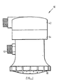
- Figure 1 is a side elevation
- Figure 2 is a side sectional elevation of a device in accordance with the invention.
- the device indicated generally at 10 is a water heater with combined shower head.
- the tubular housing 52 of the device is closed at its top end by a cap assembly 34 and at its lower end terminates in a shower rose head 18.
- the housing 52 has a lateral water inlet 12 through which water enters a water heating chamber 20. Water leaves the chamber 20 via an outlet nozzle 16 at the upper end of a downwardly directed outlet tube 51 which opens at its lower end to the shower rose 18.
- the inlet 12 has a restriction 14 related to the restriction represented by the nozzle 16 such that the volume of water entering the heating chamber 20 cannot exceed the volume escaping from it.
- the nozzle 16 is adapted to atomise the water entering the tube 51, i.e. to turn it into an aerosol spray, before it emerges from a shower rose head 18. This process of atomising the water through nozzle 16 enhances the safety of the device 10 since any current leakage to the water is dissipated almost entirely.
- a coiled heating element 22 is mounted on a support assembly 24 in the heating chamber 20.
- the element 22 is a coiled, non-ferrous bare or uninsulated element wound around the support assembly 24, the latter preferably being moulded from a light weight, strong thermoplastics material with a melting point of up to 400 degrees centigrade.
- the assembly 24 comprises four separate, identical segments which interlock on assembly. The individual segments have holes 26 to enable free passage of water so that the water will come into contact with a high proportion of the surface of the element 22. Because of the design of the assembly 24 combined with use of an uninsulated heating element 22 greater thermal efficiency is achieved thereby allowing the element 22 to be of a relatively low resistance type, resulting in longer life expectancy and lower current consumption.
- the non-ferrous element 22 is corrosion resistant which should further enhance the life expectancy of this component.
- An electrical switching mechanism to control the supply of current to the element 22 comprises a pair of movable contacts 28 mounted in a watertight manner by a rigid support washer 30 on a flexible diaphragm 32 which forms the roof of the heating chamber 20.
- the terminals 28 are connected at their lower ends to the ends of the element 22 and a semi-rigid wire support (not shown) connects the support assembly 24 to the flexible diaphragm 32 in a spaced-apart relation but such that the element 22 on its support 24 moves up and down in sympathy with the diaphragm 32.
- the cap assembly 34 is secured to the housing 52 by cooperating screw threads 53 during assembly of the device 10.
- the periphery of the diaphragm 32 is thus clamped between the cap 34 and housing 52 and forms a watertight seal.
- Mounted on the cap 34 are fixed contacts 36 positioned so that they will touch the respective movable contacts 28 when the latter rise with the diaphragm 32.
- the device 10 is in an inoperative mode. Under the influence of gravity the element 22 and its support assembly 24 have pulled the diaphragm 32 downward so that the fixed 36 and movable 28 contacts are spaced apart.
- water is admitted to the heating chamber 20 through the inlet 12 its pressure will raise the diaphragm 32 until the contacts 28 touch the contacts 36 so that the heating element 22 is energised.
- the upper ends of the fixed contacts or terminals 36 and 38 have respectively connected to them the live, neutral and earth wires of an electric cable (not shown) entering the device 10 through a terminal cover 42 mounted on the cap 34.
- An inlet duct 54 of the terminal cover is externally threaded to receive a cable gland.
- the terminal cover 42 is rotatable relative to the cap 34 to provide freedom of cable positioning during installation of the device 10.
- the duct 54 has a restriction 44 intended to minimise the possibility of water entering the area of the electrical contacts from this source.
- the cap 34 has a peripheral well or recess 46 in which water can collect to keep it away from the electrical contacts.
- the removable shower head or rose cap 18 is connected to the housing 52 by a quick-release thread 55 such that it will release from the housing 52 in approximately a quarter turn.
- the rose cap 18 includes an integrally moulded sealing formation 48 which removes the necessity for a rubber sealing ring or the like which can become detached and lost. Sealing is automatic as the rose head 18 is screwed onto the housing 52.
- the outlet holes 50 of the rose cap 18 are each tapered similarly to a funnel. It has been found that this allows easy cleaning of the shower rose 18 since dirt lodges in the tapered holes and can be removed merely by releasing the rose 18 from the unit and banging lightly in an inverted position against a firm surface. This arrangement contrasts favourably with conventional roses the holes of which normally have to be cleaned individually e.g. by pushing a pin through the hole.
- the disclosed switching method although simple is extremely robust and in operation it is expected that the contacts will not need attention during the lifetime of the device. This contrasts favourably with devices using micro switches which do not adequately cope with the 5 to 7 kw current passing through them so that they burn and require early replacement.
- the device is primarily made from moulded durable plastics material which is of course non-conductive or corrosive.
- the device of the invention would normally include an earth arrangement in the form of a length of wire bared (i.e. stripped of insulation) at one end and located in the zone of the emergent aerosol spray and taken separately to earth. This arrangement could be advantageous in areas prone to frequent electrical thunder storms.
Landscapes
- Engineering & Computer Science (AREA)
- Physics & Mathematics (AREA)
- Thermal Sciences (AREA)
- Chemical & Material Sciences (AREA)
- Combustion & Propulsion (AREA)
- Mechanical Engineering (AREA)
- General Engineering & Computer Science (AREA)
- Instantaneous Water Boilers, Portable Hot-Water Supply Apparatuses, And Control Of Portable Hot-Water Supply Apparatuses (AREA)
- Bathtubs, Showers, And Their Attachments (AREA)
- Nozzles (AREA)
Claims (8)
Priority Applications (1)
| Application Number | Priority Date | Filing Date | Title |
|---|---|---|---|
| AT85301074T ATE57758T1 (de) | 1984-02-20 | 1985-02-19 | Elektrischer wassererhitzer. |
Applications Claiming Priority (2)
| Application Number | Priority Date | Filing Date | Title |
|---|---|---|---|
| ZW29/84A ZW2984A1 (en) | 1984-02-20 | 1984-02-20 | Electrically operated water heating device |
| ZW2984 | 1984-02-20 |
Publications (3)
| Publication Number | Publication Date |
|---|---|
| EP0164816A2 EP0164816A2 (de) | 1985-12-18 |
| EP0164816A3 EP0164816A3 (en) | 1987-10-07 |
| EP0164816B1 true EP0164816B1 (de) | 1990-10-24 |
Family
ID=25590251
Family Applications (1)
| Application Number | Title | Priority Date | Filing Date |
|---|---|---|---|
| EP19850301074 Expired - Lifetime EP0164816B1 (de) | 1984-02-20 | 1985-02-19 | Elektrischer Wassererhitzer |
Country Status (10)
| Country | Link |
|---|---|
| EP (1) | EP0164816B1 (de) |
| AP (1) | AP41A (de) |
| AT (1) | ATE57758T1 (de) |
| AU (1) | AU580578B2 (de) |
| DE (1) | DE3580191D1 (de) |
| ES (1) | ES540515A0 (de) |
| NZ (1) | NZ211161A (de) |
| PT (1) | PT79976B (de) |
| ZA (1) | ZA851153B (de) |
| ZW (1) | ZW2984A1 (de) |
Families Citing this family (5)
| Publication number | Priority date | Publication date | Assignee | Title |
|---|---|---|---|---|
| DE3626955A1 (de) * | 1986-08-08 | 1988-02-18 | Bosch Siemens Hausgeraete | Durchlauferhitzer |
| NZ334223A (en) * | 1996-08-19 | 2000-05-26 | Joao Carlos Martins Gomes | Electric shower head comprising a shell-shaped body |
| GB2395899B (en) * | 2002-12-02 | 2005-02-09 | Michael Weir | Instant boiling water tap |
| BRPI0905319B1 (pt) * | 2009-12-04 | 2020-09-24 | Cláudio Lourenço Lorenzetti | Aperfeiçoamento em chuveiro elétrico |
| US9052121B2 (en) | 2011-11-30 | 2015-06-09 | Intelligent Energy, Llc | Mobile water heating apparatus |
Family Cites Families (3)
| Publication number | Priority date | Publication date | Assignee | Title |
|---|---|---|---|---|
| AU489438B2 (en) * | 1975-08-01 | 1977-02-03 | Lorenzetti Lorenzo | Water heating device |
| FR2376702A1 (fr) * | 1977-01-10 | 1978-08-04 | Lorenzetti Alexandre | Douche a chauffage electrique |
| IL59790A0 (en) * | 1979-04-17 | 1980-06-30 | Kozyheat Ltd | Water heater and regulating valve for use therewith |
-
1984
- 1984-02-20 ZW ZW29/84A patent/ZW2984A1/xx unknown
-
1985
- 1985-02-14 AU AU38719/85A patent/AU580578B2/en not_active Ceased
- 1985-02-15 ZA ZA851153A patent/ZA851153B/xx unknown
- 1985-02-15 PT PT79976A patent/PT79976B/pt not_active IP Right Cessation
- 1985-02-19 ES ES540515A patent/ES540515A0/es active Granted
- 1985-02-19 AP APAP/P/1985/000007A patent/AP41A/en active
- 1985-02-19 EP EP19850301074 patent/EP0164816B1/de not_active Expired - Lifetime
- 1985-02-19 NZ NZ211161A patent/NZ211161A/xx unknown
- 1985-02-19 AT AT85301074T patent/ATE57758T1/de not_active IP Right Cessation
- 1985-02-19 DE DE8585301074T patent/DE3580191D1/de not_active Expired - Fee Related
Also Published As
| Publication number | Publication date |
|---|---|
| ES8603057A1 (es) | 1985-12-01 |
| ATE57758T1 (de) | 1990-11-15 |
| DE3580191D1 (de) | 1990-11-29 |
| ZW2984A1 (en) | 1987-06-24 |
| AP8500007A0 (en) | 1985-02-01 |
| ES540515A0 (es) | 1985-12-01 |
| AU580578B2 (en) | 1989-01-19 |
| PT79976A (en) | 1985-03-01 |
| AP41A (en) | 1989-05-04 |
| NZ211161A (en) | 1989-01-06 |
| AU3871985A (en) | 1985-08-29 |
| ZA851153B (en) | 1985-09-25 |
| PT79976B (en) | 1986-10-28 |
| EP0164816A2 (de) | 1985-12-18 |
| EP0164816A3 (en) | 1987-10-07 |
Similar Documents
| Publication | Publication Date | Title |
|---|---|---|
| US5437003A (en) | In line tankless water heater with upper heating compartment, lower wiring compartment, and microswitch compartment disposed therebetween | |
| US6536458B1 (en) | Device for heating a tap | |
| GB2208332A (en) | Switched, cordless electrical appliances | |
| EP0164816B1 (de) | Elektrischer Wassererhitzer | |
| US3867610A (en) | Electric heating apparatus for heating a liquid by electrical conduction | |
| GB1470366A (en) | Electric immersion heaters | |
| US2588314A (en) | Electric heater | |
| US4153833A (en) | Electric hot plate assembly with a temperature limiter | |
| US1689004A (en) | Apparatus for waving hair | |
| CA1262928A (en) | Electrically operated water heating device | |
| US2757272A (en) | Apparatus for the heating of liquids | |
| US3450860A (en) | Liquid heater with high temperature safety control | |
| US1362356A (en) | Instantaneous electbic wateb-heateb | |
| RU2215946C1 (ru) | Электродный нагреватель воды (варианты) | |
| GB2193563A (en) | Liquid heater | |
| US1773546A (en) | Electric immersion heater | |
| US6072937A (en) | Steam generator | |
| BG103184A (en) | Electric water shower | |
| US2957069A (en) | Instantaneous heater for liquids | |
| US1699323A (en) | Electric heater | |
| GB2012944A (en) | Improvements in and Relating to a Heating Installation and a Valve Therefor | |
| GB1430229A (en) | Electric immersion heaters and thermal control units therefor | |
| EP0686815A1 (de) | Elektronisches Durchflussheizelement für Medien | |
| CN214960156U (zh) | 一种电加热器 | |
| KR100193877B1 (ko) | 인입수 온도 조절 장치 |
Legal Events
| Date | Code | Title | Description |
|---|---|---|---|
| PUAI | Public reference made under article 153(3) epc to a published international application that has entered the european phase |
Free format text: ORIGINAL CODE: 0009012 |
|
| AK | Designated contracting states |
Designated state(s): AT BE CH DE FR GB IT LI LU NL SE |
|
| PUAL | Search report despatched |
Free format text: ORIGINAL CODE: 0009013 |
|
| AK | Designated contracting states |
Kind code of ref document: A3 Designated state(s): AT BE CH DE FR GB IT LI LU NL SE |
|
| 17P | Request for examination filed |
Effective date: 19880218 |
|
| RAP1 | Party data changed (applicant data changed or rights of an application transferred) |
Owner name: STEAMY PRODUCTS (PRIVATE) LIMITED |
|
| 17Q | First examination report despatched |
Effective date: 19890803 |
|
| GRAA | (expected) grant |
Free format text: ORIGINAL CODE: 0009210 |
|
| AK | Designated contracting states |
Kind code of ref document: B1 Designated state(s): AT BE CH DE FR GB IT LI LU NL SE |
|
| REF | Corresponds to: |
Ref document number: 57758 Country of ref document: AT Date of ref document: 19901115 Kind code of ref document: T |
|
| ITF | It: translation for a ep patent filed | ||
| REF | Corresponds to: |
Ref document number: 3580191 Country of ref document: DE Date of ref document: 19901129 |
|
| RIN2 | Information on inventor provided after grant (corrected) |
Free format text: HOLLAND, JOHN DAVID |
|
| ET | Fr: translation filed | ||
| PLBE | No opposition filed within time limit |
Free format text: ORIGINAL CODE: 0009261 |
|
| STAA | Information on the status of an ep patent application or granted ep patent |
Free format text: STATUS: NO OPPOSITION FILED WITHIN TIME LIMIT |
|
| 26N | No opposition filed | ||
| PGFP | Annual fee paid to national office [announced via postgrant information from national office to epo] |
Ref country code: CH Payment date: 19920129 Year of fee payment: 8 |
|
| PGFP | Annual fee paid to national office [announced via postgrant information from national office to epo] |
Ref country code: LU Payment date: 19920130 Year of fee payment: 8 |
|
| PGFP | Annual fee paid to national office [announced via postgrant information from national office to epo] |
Ref country code: GB Payment date: 19920212 Year of fee payment: 8 |
|
| PGFP | Annual fee paid to national office [announced via postgrant information from national office to epo] |
Ref country code: SE Payment date: 19920220 Year of fee payment: 8 |
|
| PGFP | Annual fee paid to national office [announced via postgrant information from national office to epo] |
Ref country code: FR Payment date: 19920225 Year of fee payment: 8 |
|
| ITTA | It: last paid annual fee | ||
| PGFP | Annual fee paid to national office [announced via postgrant information from national office to epo] |
Ref country code: NL Payment date: 19920229 Year of fee payment: 8 Ref country code: AT Payment date: 19920229 Year of fee payment: 8 |
|
| PGFP | Annual fee paid to national office [announced via postgrant information from national office to epo] |
Ref country code: DE Payment date: 19920414 Year of fee payment: 8 |
|
| PGFP | Annual fee paid to national office [announced via postgrant information from national office to epo] |
Ref country code: BE Payment date: 19920514 Year of fee payment: 8 |
|
| EPTA | Lu: last paid annual fee | ||
| PG25 | Lapsed in a contracting state [announced via postgrant information from national office to epo] |
Ref country code: LU Free format text: LAPSE BECAUSE OF NON-PAYMENT OF DUE FEES Effective date: 19930219 Ref country code: GB Effective date: 19930219 Ref country code: AT Effective date: 19930219 |
|
| PG25 | Lapsed in a contracting state [announced via postgrant information from national office to epo] |
Ref country code: SE Effective date: 19930220 |
|
| PG25 | Lapsed in a contracting state [announced via postgrant information from national office to epo] |
Ref country code: LI Effective date: 19930228 Ref country code: CH Effective date: 19930228 Ref country code: BE Effective date: 19930228 |
|
| BERE | Be: lapsed |
Owner name: STEAMY PRODUCTS (PRIVATE) LTD Effective date: 19930228 |
|
| PG25 | Lapsed in a contracting state [announced via postgrant information from national office to epo] |
Ref country code: NL Effective date: 19930901 |
|
| GBPC | Gb: european patent ceased through non-payment of renewal fee |
Effective date: 19930219 |
|
| NLV4 | Nl: lapsed or anulled due to non-payment of the annual fee | ||
| PG25 | Lapsed in a contracting state [announced via postgrant information from national office to epo] |
Ref country code: FR Effective date: 19931029 |
|
| REG | Reference to a national code |
Ref country code: CH Ref legal event code: PL |
|
| PG25 | Lapsed in a contracting state [announced via postgrant information from national office to epo] |
Ref country code: DE Effective date: 19931103 |
|
| REG | Reference to a national code |
Ref country code: FR Ref legal event code: ST |
|
| EUG | Se: european patent has lapsed |
Ref document number: 85301074.2 Effective date: 19930912 |