EP0164955A1 - Stopper remover - Google Patents
Stopper remover Download PDFInfo
- Publication number
- EP0164955A1 EP0164955A1 EP85303769A EP85303769A EP0164955A1 EP 0164955 A1 EP0164955 A1 EP 0164955A1 EP 85303769 A EP85303769 A EP 85303769A EP 85303769 A EP85303769 A EP 85303769A EP 0164955 A1 EP0164955 A1 EP 0164955A1
- Authority
- EP
- European Patent Office
- Prior art keywords
- stopper
- bottle
- jaws
- remover
- jaw members
- Prior art date
- Legal status (The legal status is an assumption and is not a legal conclusion. Google has not performed a legal analysis and makes no representation as to the accuracy of the status listed.)
- Withdrawn
Links
- 230000002093 peripheral effect Effects 0.000 claims description 7
- 230000000903 blocking effect Effects 0.000 claims description 3
- 230000008093 supporting effect Effects 0.000 claims description 3
- 235000019993 champagne Nutrition 0.000 abstract description 7
- 210000003811 finger Anatomy 0.000 description 12
- 239000007789 gas Substances 0.000 description 3
- 235000015040 sparkling wine Nutrition 0.000 description 3
- 230000006378 damage Effects 0.000 description 2
- 230000014759 maintenance of location Effects 0.000 description 2
- 208000027418 Wounds and injury Diseases 0.000 description 1
- 230000000295 complement effect Effects 0.000 description 1
- 238000010276 construction Methods 0.000 description 1
- 239000007799 cork Substances 0.000 description 1
- 210000003414 extremity Anatomy 0.000 description 1
- 208000014674 injury Diseases 0.000 description 1
- 230000005923 long-lasting effect Effects 0.000 description 1
- 210000003141 lower extremity Anatomy 0.000 description 1
- 238000004519 manufacturing process Methods 0.000 description 1
- 238000000034 method Methods 0.000 description 1
- 239000013641 positive control Substances 0.000 description 1
- 230000000717 retained effect Effects 0.000 description 1
- 210000003813 thumb Anatomy 0.000 description 1
Images

Classifications
-
- B—PERFORMING OPERATIONS; TRANSPORTING
- B67—OPENING, CLOSING OR CLEANING BOTTLES, JARS OR SIMILAR CONTAINERS; LIQUID HANDLING
- B67B—APPLYING CLOSURE MEMBERS TO BOTTLES JARS, OR SIMILAR CONTAINERS; OPENING CLOSED CONTAINERS
- B67B7/00—Hand- or power-operated devices for opening closed containers
- B67B7/02—Hand- or power-operated devices for opening closed containers for removing stoppers
- B67B7/06—Other cork removers
- B67B7/066—Other cork removers specially adapted for opening pressurised bottles, e.g. champagne or sparkling wine bottles
Definitions
- Sparkling wines and champagnes are traditionally provided in a bottle having a plastic or cork stopper which, in addition to being safety wired, is retained by a friction fit within the mouth of the bottle.
- Such secure retention means must be provided to prevent pressurized gas within the bottle from pushing the stopper out.
- stoppers With or without a towel, stoppers sometimes generate much more retention friction than is desirable and ultimately are very difficult to remove. This is especially troublesome in commercial establishments where many bottles must be opened in a short time. There are also times when a bottle has been agitated and the friction forces between stopper and the bottle are insufficient to overcome the now highly pressurized gas so that the stopper flies free as the safety wire is removed. This dangerous and unexpected result can occur when the bottle is facing an eye or other easily damaged article. Therefore, a simple, economical, safe, and easy to operate stopper remover which can prevent flight of the stopper under all conditions has been needed.
- Another object is to provide a champagne stopper remover which can be constructed relatively ecomonically and yet is sturdy and longlasting.
- Another object is to provide a tool for removing stoppers from champagne bottles which prevents dangerous unrestricted flight of the stopper without reducing the festive "pop" normally associated therewith.
- Another object is to provide a tool for removing stoppers from champagne bottles which eliminates surprise stopper flight when the safety wires are removed.
- the invention provides a stopper remover for removing a stopper which partially projects from the neck of a bottle having exterior upwardly and outwardy facing peripheral surfaces, such remover being of the type including a frame for mounting on the bottle, elongate pivotal jaw members formed on their respective one ends with pivot ends and on the opposite ends with inturned confronting jaws biased together for engagement with the opposite sides of the projecting portion of said stopper and, a lever arm pivotally mounted between said frame and jaws and including a handle projecting therefrom, and further comprising: an elongate axial frame member formed on one end with a pad for engaging the side of a bottle neck and on its opposite end with a pivot end: a pair of yoke fingers-projecting laterally of said frame member, spaced apart a predetermined distance and disposed on the opposite sides of the axis of said frame member, said fingers being formed with inclined abutment surfaces facing inwardly toward one another and toward said pad for engagement with said upwardly and outwardly facing peripheral bottle surface to
- number 10 in FIGS. 1 and 2 refers to a tool for removing a stopper 12 from a champagne, sparkling wine or other pressurized bottle 14 whose neck 16 and safety wires 17 only are shown.
- the tool 10 includes a frame 18 which has a lower pad 20 with a concave inner abutment surface 22 (FIG. 3) adapted for engagement with the lateral periphery of the neck 16 of the bottle 14 and a laterally extending yoke 24 (FIG. 4) for engagement with the upwardly and inwardly inclined surface 26 of the lip 28 of the bottle 14.
- the yoke 24 is cast integral with the frame 1 8 and extends laterally therefrom in the form of two generally parallel fingers 30 and 32. As shown in FIGS. 5 and 6, the fingers 30 and 32 are each formed at their free extremities with respective downwardly and inwardly facing oppositely disposed chamfered abutment surfaces 34 and 36 respectively which are oriented to generally complement the angle of the upwardly facing surface 26 of the bottle lip 28.
- the bottle 14 is twisted so that the safety wires 17 extend diagonally across the stopper 12 and the fingers 30 and 32 of the yoke 24 are slid sidewardly toward the bottle 14 until the oppositely disposed abutment surfaces 34 and 36 are engaged with the upwardly facing surface 26 of the lip 24.
- the upper surfaces 38 and 40 of the yoke fingers 30 and 32 respectively are simultaneously aligned with or below the radial flange 42 formed on the underside of the head 44 of the stopper 12 while the concave abutment surface 22 of the pad 18 is brought into contact with the side of the bottle neck 16. This is generally the position shown in FIG. 1.
- the fingers 30 and 32 of the yoke 24 extend longitudinally beyond their tangential contact points with the upper lip surface 26 and are slightly canted away from each other. This allows the yoke 10 to be placed or wedged onto bottles 14 having different diameter lips 28 while remaining clear of the safety wires 17 to permit free access thereto for removal.
- An elongated lever handle 46 is connected at one end 48 to the upper end 50 of the frame by means of a pivot pin 52 to allow rotative movement as shown by the arrow 54 (FIG. 2).
- the end 48 of the lever 46 is itself a bifurcated clevis forming a pair of laterally spaced apart parallel fingers 56 and 58 which extend from the pivot pin 52, laterally over the stopper 12 (FIG. 1) to a downturned intermediate portion 60 which is connected with a hand grasp handle portion 62.
- a pair of outwardly and downwardly extending jaw members 64 and 66 are disposed in the same plane as the lever 46 and are suspended centrally from the bifurcated handle fingers 56 and 58 by means of a common pivot pin 74 (FIGS. 1 and 2).
- the jaw members 64 and 66 are identical, each having a slightly laterally offset upper portion 69 and 71 (FIG. 1) which overlap and are connected generally at the central portion 72 of the fingers 56 and 58 by means of the pivot pin 74.
- the jaw pivot pin 74 is generally parallel to the handle pivot pin 52, the abutment surfaces 34 and 36 and the upper surfaces 68 and 70, and is positioned generally at right angles to the lever 46 and the base 18.
- the jaw members 64 and 66 are free to pivot but are biased together by a tension spring 76 which extends therebetween and is formed on its opposite ends with hooks which connect through transverse bores 78 and 80 (FIG. 7) formed in the central shank portion 82 and 84 of each jaw member 64 and 66.
- the jaw members 64 and 66 are formed on their lower extremities with inturned confronting jaws 86 and 88 respectively.
- the jaws 86 and 88 are formed with respective downwardly and inwardly facing similar concave conical surfaces 90 and 92 which taper downwardly to meet with horizontal undersides 94 and 96 (FIG. 2).
- the conical surfaces 90 and 92 join at their upper ends with horizontal upper surfaces 68 and 70 to form semi-circular edges or teeth 97 and 98, respectively, each having a radius slightly larger than the radius of the stopper head 12 to assist in wedging between the head 12 and the lip 28.
- the arc subtended by a single jaw edge 97 and 98 preferably is less than 90° so that it can fit between adjacent safety wires 17.
- Such fingers Projecting laterally inwardly from the central portions 82 and 84 of the jaw members 64 and 66 are blocker fingers 102 and 104.
- Such fingers are formed with downwardly facing blocking jaws 106 and 108, respectively, and terminate in respecting confronting ends 110 and 112 which are spaced apart a distance sufficient to engage one another and maintain the jaws 86 and 88 normally spaced apart a distance sufficient to maintain the downwardly facing conical surfaces spaced apart a distance sufficient to cause such surfaces to engage the laterally opposite sides of the top of the stopper head 44 when the remover is being applied to the bottle such that lowering of such jaws on the stopper head will cause such jaws to be spread apart.
- Such spacing is also sufficient to accommodate closure of the jaws 86 and 88 toward one another to a sufficient degree to enable firm engagement thereof, beneath the flange 42 of the head 100. It will be noted that when the handle 62 is in the closed position shown in FIG. 2, the jaws 86 and 88 project into the plane of and are received between the fingers 30 and 32.
- the user may grasp the frame 18, rotate the handle 62 counterclockwise as depicted by the directional arrow in FIG. 2 to raise the jaws 86 and 88. He or she may then manipulate the tines 38 and 40 of the yoke 24 into position on the opposite sides of the bottle lip 28 to engage the downwardly and inwardly facing abutments surfaces 34 and 36 with the upwardly and outwardly facing lip surface 26 (FIG. 5) to nest such yoke securely on the lips while engaging the pad 22 (FIG. 2) with the lateral surface of the bottle neck 16.
- the frame 18 With the frame securely supported on the three point contact defined by engagement of such abutment surfaces 34 and 36 with the lip surface 26 and the pad surface 22 with the lateral surface of the neck 16, the frame 18 is supported securely in position and the handle 62 may then be lowered to pivot such handle clockwise about the handle pivot pin 52 (FIG. 2) to lower the jaw members 64 and 66.
- the handle 62 may then be rotated upwardly and outwardly in a counterclockwise direction about the handle pivot pin 52. Downward shifting of the frame 18 will be resisted by support of the abutment surfaces 34 and 36 on the lip 28 (FIG. 5), as complemented by the supporting action of the pad against the bottle neck 16.
- the retaining wires 17 may then be severed or untwisted to release the stopper 1 2, while the user holds the remover firmly in position. In the event pressure has built up under the stopper 12 to a point which will cause abrupt release of the stopper, such stopper will be engaged against the under surfaces 106 and 108 of the blockers 102 and 104 (FIG. 2) thus blocking such stopper erratic and uncontrolled release to be propelled about the room causing possible injury or discomfort to standersby.
- the stopper remover of the present invention provides a device which is relatively economical to manufacture and is sturdy in construction thus providing for long and trouble free life.
- the remover provides for positive control of the stopper during the removal procedure while being convenient to operate.
Landscapes
- Engineering & Computer Science (AREA)
- Mechanical Engineering (AREA)
- Devices For Opening Bottles Or Cans (AREA)
Abstract
A tool for removing headed stoppers from bottles such as champagne bottles, includes a base (18) having a two fingered yoke (30, 32) and a side support (20), sized and shaped to engage the upper lip and the side of the neck of the bottle respectively, so that when a handle (46), pivotally attached to the base, is lowered towards the bottle, a pair of inwardly biased jaws (64,66) slide down over the head of the stopper to engage its undersurface between the fingers of the yoke. Thereafter, the handle is lifted extracting the stopper while inwardly facing extensions (102, 104) positioned above the stopper on the jaws restrict upward motion of the stopper to prevent uncontrolled motion thereof.
Description
- Sparkling wines and champagnes are traditionally provided in a bottle having a plastic or cork stopper which, in addition to being safety wired, is retained by a friction fit within the mouth of the bottle. Such secure retention means must be provided to prevent pressurized gas within the bottle from pushing the stopper out. Although at festive occasions it is sometimes desired to "pop" the stopper by gripping the bottle and slowly working the stopper out using ones thumbs so that it flies upwardly, such presents the danger of a flying stopper in commercial establishments and is unwise in a crowded gathering. The flying stopper may also damage the ceiling. Therefore, towels commonly are wrapped around the bottle to dampen the stopper's flight. The towel is'disadvantageous because it makes the stopper removal clumsy and silences the festive "pop". With or without a towel, stoppers sometimes generate much more retention friction than is desirable and ultimately are very difficult to remove. This is especially troublesome in commercial establishments where many bottles must be opened in a short time. There are also times when a bottle has been agitated and the friction forces between stopper and the bottle are insufficient to overcome the now highly pressurized gas so that the stopper flies free as the safety wire is removed. This dangerous and unexpected result can occur when the bottle is facing an eye or other easily damaged article. Therefore, a simple, economical, safe, and easy to operate stopper remover which can prevent flight of the stopper under all conditions has been needed.
- Therefore it is an object of the present invention to provide a tool for quickly removing stoppers from sparkling wine and champagne bottles by a person of minimal strength.
- Another object is to provide a champagne stopper remover which can be constructed relatively ecomonically and yet is sturdy and longlasting.
- Another object is to provide a tool for removing stoppers from champagne bottles which prevents dangerous unrestricted flight of the stopper without reducing the festive "pop" normally associated therewith.
- Another object is to provide a tool for removing stoppers from champagne bottles which eliminates surprise stopper flight when the safety wires are removed.
- These objects are achieved in that the invention provides a stopper remover for removing a stopper which partially projects from the neck of a bottle having exterior upwardly and outwardy facing peripheral surfaces, such remover being of the type including a frame for mounting on the bottle, elongate pivotal jaw members formed on their respective one ends with pivot ends and on the opposite ends with inturned confronting jaws biased together for engagement with the opposite sides of the projecting portion of said stopper and, a lever arm pivotally mounted between said frame and jaws and including a handle projecting therefrom, and further comprising: an elongate axial frame member formed on one end with a pad for engaging the side of a bottle neck and on its opposite end with a pivot end: a pair of yoke fingers-projecting laterally of said frame member, spaced apart a predetermined distance and disposed on the opposite sides of the axis of said frame member, said fingers being formed with inclined abutment surfaces facing inwardly toward one another and toward said pad for engagement with said upwardly and outwardly facing peripheral bottle surface to cooperate with said in supporting said frame from said bottle; said lever arm being pivotally connected on one end with said pivot end of said frame and pivotally connected intermediately with said pivot ends of said respective jaw members for rotation in one direction to draw said jaws in a direction away from said pad whereby said frame may be mounted on said bottle with said pad and abutment surfaces engaged therewith such that rotation of said lever arm in said one direction will draw said jaws into engagement with the opposite sides of the projection portion of said stopper and continued rotation in said one direction will draw said stopper from the neck of said bottle.
- By way of Example, an embodiment of the invention will now be described with reference to the accompanying drawings, in which:
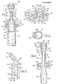
- Figure 1 is a perspective view of a stopper removal tool constructed according to the present invention;
- Referring to the drawings more particularly by reference numbers,
number 10 in FIGS. 1 and 2 refers to a tool for removing astopper 12 from a champagne, sparkling wine or other pressurizedbottle 14 whoseneck 16 andsafety wires 17 only are shown. Thetool 10 includes aframe 18 which has alower pad 20 with a concave inner abutment surface 22 (FIG. 3) adapted for engagement with the lateral periphery of theneck 16 of thebottle 14 and a laterally extending yoke 24 (FIG. 4) for engagement with the upwardly and inwardlyinclined surface 26 of thelip 28 of thebottle 14. - The
yoke 24 is cast integral with the frame 18 and extends laterally therefrom in the form of two generallyparallel fingers fingers abutment surfaces surface 26 of thebottle lip 28. When thetool 10 is to be used, thebottle 14 is twisted so that thesafety wires 17 extend diagonally across thestopper 12 and thefingers yoke 24 are slid sidewardly toward thebottle 14 until the oppositely disposedabutment surfaces surface 26 of thelip 24. Theupper surfaces yoke fingers radial flange 42 formed on the underside of thehead 44 of thestopper 12 while theconcave abutment surface 22 of thepad 18 is brought into contact with the side of thebottle neck 16. This is generally the position shown in FIG. 1. As can be seen in FIG. 1, thefingers yoke 24 extend longitudinally beyond their tangential contact points with theupper lip surface 26 and are slightly canted away from each other. This allows theyoke 10 to be placed or wedged ontobottles 14 havingdifferent diameter lips 28 while remaining clear of thesafety wires 17 to permit free access thereto for removal. - An
elongated lever handle 46 is connected at oneend 48 to theupper end 50 of the frame by means of apivot pin 52 to allow rotative movement as shown by the arrow 54 (FIG. 2). Theend 48 of thelever 46 is itself a bifurcated clevis forming a pair of laterally spaced apartparallel fingers pivot pin 52, laterally over the stopper 12 (FIG. 1) to a downturnedintermediate portion 60 which is connected with a handgrasp handle portion 62. - A pair of outwardly and downwardly extending
jaw members lever 46 and are suspended centrally from the bifurcatedhandle fingers jaw members upper portion 69 and 71 (FIG. 1) which overlap and are connected generally at thecentral portion 72 of thefingers pivot pin 74. Thejaw pivot pin 74 is generally parallel to thehandle pivot pin 52, theabutment surfaces upper surfaces lever 46 and thebase 18. Thejaw members tension spring 76 which extends therebetween and is formed on its opposite ends with hooks which connect throughtransverse bores 78 and 80 (FIG. 7) formed in thecentral shank portion jaw member jaw members jaws - The
jaws conical surfaces horizontal undersides 94 and 96 (FIG. 2). Theconical surfaces upper surfaces teeth stopper head 12 to assist in wedging between thehead 12 and thelip 28. The arc subtended by asingle jaw edge adjacent safety wires 17. - Projecting laterally inwardly from the
central portions jaw members blocker fingers jaws ends jaws stopper head 44 when the remover is being applied to the bottle such that lowering of such jaws on the stopper head will cause such jaws to be spread apart. Such spacing is also sufficient to accommodate closure of thejaws flange 42 of thehead 100. It will be noted that when thehandle 62 is in the closed position shown in FIG. 2, thejaws fingers - In operation, when it is desirable to remove a
stopper 12 from abottle neck 16, the user may grasp theframe 18, rotate thehandle 62 counterclockwise as depicted by the directional arrow in FIG. 2 to raise thejaws tines yoke 24 into position on the opposite sides of thebottle lip 28 to engage the downwardly and inwardly facingabutments surfaces bottle neck 16. With the frame securely supported on the three point contact defined by engagement ofsuch abutment surfaces lip surface 26 and thepad surface 22 with the lateral surface of theneck 16, theframe 18 is supported securely in position and thehandle 62 may then be lowered to pivot such handle clockwise about the handle pivot pin 52 (FIG. 2) to lower thejaw members - Such lowering of the
jaw members conical surfaces jaws such head 44. Such downward travel will be continued until theedges flange 42 formed at the bottom periphery of thehead 44. At this point, the operator will feel a slight inward movement of thejaw member jaws handle 62 may then be rotated upwardly and outwardly in a counterclockwise direction about thehandle pivot pin 52. Downward shifting of theframe 18 will be resisted by support of theabutment surfaces bottle neck 16. Theretaining wires 17 may then be severed or untwisted to release thestopper 12, while the user holds the remover firmly in position. In the event pressure has built up under thestopper 12 to a point which will cause abrupt release of the stopper, such stopper will be engaged against the undersurfaces blockers 102 and 104 (FIG. 2) thus blocking such stopper erratic and uncontrolled release to be propelled about the room causing possible injury or discomfort to standersby. - Thereafter, continued upward movement of the
handle 62 in the direction of the arrow 54 shown in FIG. 2 will exert an upward force under theflange 42 of thestopper head 44, which force will be resisted by engagement of theabutment surfaces handle 62 is continued the central disposition of thejaw pin 74 will tend to draw thejaw members jaws jaw edges stopper flange 42 and thelip 28. Such radial inwardly forces on thejaws flange 42 such that continued upward shifting of thehandle 62 will lift thestopper 12 to draw thestopper shank 100 upwardly relative to thebottle neck 16. As withdrawal of thestopper 12 is continued, a point will be reached wherein the frictional resistance to movement of theshank 100 within theneck 16 will be reduced to the point where the gaseous pressure built up within the bottle will overcome such frictional resistance thus tending to drive thestopper 12 from the bottle neck. Such forced ejection of thestopper 12 will be limited by engagement of the stop thereof with the downwardly facingblocker surfaces stopper 12 may be gently and controllably removed. - From the foregoing, it will be apparent that the stopper remover of the present invention provides a device which is relatively economical to manufacture and is sturdy in construction thus providing for long and trouble free life. The remover provides for positive control of the stopper during the removal procedure while being convenient to operate.
Claims (8)
1. A stopper remover for removing a stopper (12) which partially projects from the neck (16) of a bottle (14) having exterior upwardly and outwardly facing peripheral surfaces (26), such remover being of the type including a frame (18) for mounting on the bottle, elongate pivotal jaw members (64, 66) formed on their respective one ends with pivot ends (69, 71) and on opposite ends with inturned confronting jaws (86, 88) biased together for engagement with the opposite sides of the projecting portion of said stopper and, a lever arm (46) pivotally mounted between said frame and jaws and including a handle (62) projecting therefrom, and further comprising: an elongate axial frame member (20) formed on one end with a pad (22) for engaging the side of a bottle neck and on its opposite end (50) with a pivot end: a pair of yoke fingers (30, 32) projecting laterally of said frame member, spaced apart a predeterminmed distance and disposed on the opposite sides of the axis of said frame member, said fingers being formed with inclined abutment surfaces (34, 36) facing inwardly toward one another and toward said pad for engagement with said upwardly and outwardly facing peripheral bottle surface to cooperate with said pad in supporting said frame from said bottle; said lever arm being pivotally connected on one end (48) with said pivot end of said frame and pivotally connected intermediately with said pivot ends of said respective jaw members for rotation in one direction to draw said jaws in a direction away from said pad whereby said frame may be mounted on said bottle with said pad and abutment surfaces engaged therewith such that rotation of said lever arm in said one direction will draw said jaws into engagement with the opposite sides of the projecting portion of said stopper and continued rotation in said one direction will draw said stopper from the neck of said bottle.
2. A stopper removed as claimed in claim 1 wherein: said jaw members are formed intermediately with laterally projecting blocker fingers (102, 104) overlying said jaws for blocking uncontrolled egress of said stopper from said neck.
3. A stopper removed as claimed in claim 1 or claim 2 wherein: when said lever arm is rotated in the direction opposite said one direction said jaw member will project into the plane of said yoke fingers, said jaw members being so configured and shaped as to be received between said yoke finger.
4. A stopper remover as claimed in claim 1, claim 2 or claim 3 wherein: said jaws are formed with respective outwardly concave, conical surfaces (90, 92) facing inwardly toward one another and in the direction of said pad.
5. A stopper remover as claimed in any preceding claim wherein: said lever arm, in the stopper engagement position, projects laterally from said frame member to form an intermediate portion (58) and said remover includes a common pivot pin (74) connecting the respective one ends of said jaw members directly to said intermediate portion.
6. A stopper remover as claimed in claim 5 wherein: said intermediate portion of said lever arm is bifurcated to form a clevis and said one ends of said jaw members are received in said clevis.
7. A stopper remover as claimed in any preceding claim wherein: said jaw members lie in the same plane as said lever arm.
8. A stopper remover as claimed in any preceding claim for removing a stopper from a bottle of the type found with a peripheral lip forming said upwardly and outwardly facing peripheral surface, said pad being spaced axially from said jaws and said jaw members being sufficiently long to dispose said jaws in the plane of said yoke fingers when said lever arm is fully rotated in the direction opposite said one direction.
Applications Claiming Priority (2)
| Application Number | Priority Date | Filing Date | Title |
|---|---|---|---|
| US06/615,170 US4708033A (en) | 1984-05-30 | 1984-05-30 | Stopper remover |
| US615170 | 1984-05-30 |
Publications (1)
| Publication Number | Publication Date |
|---|---|
| EP0164955A1 true EP0164955A1 (en) | 1985-12-18 |
Family
ID=24464298
Family Applications (1)
| Application Number | Title | Priority Date | Filing Date |
|---|---|---|---|
| EP85303769A Withdrawn EP0164955A1 (en) | 1984-05-30 | 1985-05-29 | Stopper remover |
Country Status (3)
| Country | Link |
|---|---|
| US (1) | US4708033A (en) |
| EP (1) | EP0164955A1 (en) |
| ZA (1) | ZA854006B (en) |
Cited By (9)
| Publication number | Priority date | Publication date | Assignee | Title |
|---|---|---|---|---|
| WO1987000824A1 (en) * | 1985-07-29 | 1987-02-12 | Baum Frederick W | Champagne bottle opener |
| US4680993A (en) * | 1986-06-20 | 1987-07-21 | Feliz Jack M | Champagne bottle opener |
| US4750391A (en) * | 1986-04-04 | 1988-06-14 | Stan Dee, Incorporated | Opener for removing champagne-type corks |
| EP0291546A1 (en) * | 1987-05-19 | 1988-11-23 | Jack M. Feliz | Champagne bottle opener |
| EP0325011A1 (en) * | 1988-01-19 | 1989-07-26 | Ben Frederick Giebeler | Champagne bottle opener |
| DE19645565C1 (en) * | 1996-11-05 | 1998-04-23 | Braun Dieter Dipl Ing Fh | Bottle opener for sparkling wine bottles with natural corks |
| CN103569921A (en) * | 2012-07-18 | 2014-02-12 | 卓越创新有限公司 | corkscrew |
| FR3005307A1 (en) * | 2013-05-02 | 2014-11-07 | Excellence Innovation Ltd | CAPPER FOR EFFERVESCENT LIQUID BOTTLE |
| FR3136459A1 (en) * | 2022-06-14 | 2023-12-15 | Olivier LABROUE | Bottle opener for bottle containing an effervescent liquid |
Families Citing this family (22)
| Publication number | Priority date | Publication date | Assignee | Title |
|---|---|---|---|---|
| US5275070A (en) * | 1993-04-16 | 1994-01-04 | St Denis Andrew R | Device for removing wine bottle stopper |
| US5906143A (en) * | 1994-04-26 | 1999-05-25 | Yuen; Kenneth | Ink cartridge opener |
| US5483854A (en) * | 1995-03-06 | 1996-01-16 | K2 Development Corporation | Apparatus for removing cork and stoppering structure from pressurized bottle |
| US5528961A (en) * | 1995-03-28 | 1996-06-25 | Paramest; Sam | Ice bucket champagne opener |
| US5868044A (en) * | 1996-04-25 | 1999-02-09 | Sonderman; Harry P. | Bottle stopper remover |
| DE60101715T2 (en) * | 2000-10-25 | 2004-12-09 | Descorjet Sociedad Anonima | Manual device for pulling stoppers from containers for carbonated beverages, sparkling wines and the like |
| US6637295B2 (en) * | 2001-01-10 | 2003-10-28 | Darryl Weaver | Cork remover for champagne bottles or the like |
| AU785476B2 (en) * | 2001-11-27 | 2007-08-09 | Descorjet Sociedad Anonima | Manually operated stopper extractor of a container filled with carbonated beverage, sparkling wine and the like |
| DE20220476U1 (en) * | 2002-10-07 | 2003-08-21 | Fackelmann GmbH + Co. KG, 91217 Hersbruck | Corkscrew for the cork of champagne, sparkling wine, prosecco, cider bottles or the like. |
| US6736030B2 (en) | 2002-10-16 | 2004-05-18 | Mcluen Carl T. | Champagne cork remover |
| NZ528539A (en) * | 2003-09-25 | 2004-10-29 | Bryce Leslie Stewart | Stopper Removing Tool |
| US7490534B2 (en) * | 2003-12-03 | 2009-02-17 | Jorge Hine | Cork extractor apparatus and method |
| US7146878B2 (en) * | 2004-02-03 | 2006-12-12 | Nu-Kote International, Inc. | Ink container opener |
| USD515892S1 (en) | 2004-02-03 | 2006-02-28 | Nu-Kote International, Inc. | Ink container opener |
| US7128249B2 (en) * | 2004-02-25 | 2006-10-31 | Nu-Kote International, Inc. | Ink container opener |
| US7213489B2 (en) * | 2004-06-10 | 2007-05-08 | Nu-Kote International, Inc. | Ink container opener with multiple inserts for different container types |
| US20060225536A1 (en) * | 2005-04-06 | 2006-10-12 | Thomas Hill | Bottle opener for pressurized bottles |
| US7325909B2 (en) | 2005-04-28 | 2008-02-05 | Kenneth Yuen | Automatic ink refill system and methods |
| US20080186369A1 (en) * | 2007-02-02 | 2008-08-07 | Lyles Benjamin A | Remanufactured ink cartridges and methods of making the same |
| WO2009060255A1 (en) * | 2007-11-07 | 2009-05-14 | Sidel Participations | Clamp for holding a container by the neck |
| US8127588B1 (en) * | 2011-03-23 | 2012-03-06 | Halpin Harold W | Apparatus and methods for forming a finger-engaging portion in a stay-on-tab of a lid of a container |
| US10065232B2 (en) | 2013-03-15 | 2018-09-04 | Station 4 Llc | Devices and methods for bending a tab on a container |
Citations (3)
| Publication number | Priority date | Publication date | Assignee | Title |
|---|---|---|---|---|
| GB731416A (en) * | 1953-12-14 | 1955-06-08 | Charles Hardy | Improvements in or relating to cork extractors |
| US2732741A (en) * | 1956-01-31 | Moller-strobel | ||
| DE2644647A1 (en) * | 1976-10-02 | 1978-04-06 | Zerhusen | Sparkling wine bottle opener - has guide arms on neck holder to guide pull levers for puller clamps |
Family Cites Families (19)
| Publication number | Priority date | Publication date | Assignee | Title |
|---|---|---|---|---|
| US110127A (en) * | 1870-12-13 | Improvement in bung-elevators | ||
| US111207A (en) * | 1871-01-24 | Improvement in box-openers | ||
| US557546A (en) * | 1896-04-07 | Cork-extractor | ||
| US538279A (en) * | 1895-04-30 | Bung-extracting tool | ||
| US1091301A (en) * | 1913-05-08 | 1914-03-24 | Edward J Doheny | Stopper-extractor. |
| US1492908A (en) * | 1920-08-28 | 1924-05-06 | Andrew J Trumbo | Hand press |
| US1787018A (en) * | 1927-11-18 | 1930-12-30 | George V Porz | Means for removing bottle caps |
| US1728418A (en) * | 1928-03-21 | 1929-09-17 | Isaac W Litchfield | Bottle opener |
| US2335777A (en) * | 1942-04-29 | 1943-11-30 | Marcellus James Wilburn | Cover remover |
| US2484043A (en) * | 1945-11-26 | 1949-10-11 | Jarly C Malen | Pulling and pushing device |
| US2554898A (en) * | 1946-12-05 | 1951-05-29 | L I Alexander | Bottle opener |
| US2589051A (en) * | 1948-11-18 | 1952-03-11 | William A Carter | Crown cap lifter with reciprocating elements |
| US2612065A (en) * | 1948-11-18 | 1952-09-30 | Packer | Power-operated bottle opener |
| US2746323A (en) * | 1954-09-23 | 1956-05-22 | Gustav R Johnson | Pivoted lever bottle cap removing device |
| DE2116768A1 (en) * | 1971-04-06 | 1972-12-21 | Scharwat geb Strassel, Anna Maria, 6000 Frankfurt | Pincer-like opener for champagne bottles with automatic wire cutter |
| US3800345A (en) * | 1972-09-13 | 1974-04-02 | J Feliz | Champagne cork extractor and wire cutter |
| US4052917A (en) * | 1977-01-21 | 1977-10-11 | Beryl Gee | Jar and bottle cap opener |
| US4422355A (en) * | 1981-04-13 | 1983-12-27 | Burns Jr William T | Sparkling wine bottle opener |
| US4458564A (en) * | 1982-11-05 | 1984-07-10 | George Simmons | Radiator cap remover |
-
1984
- 1984-05-30 US US06/615,170 patent/US4708033A/en not_active Expired - Fee Related
-
1985
- 1985-05-27 ZA ZA854006A patent/ZA854006B/en unknown
- 1985-05-29 EP EP85303769A patent/EP0164955A1/en not_active Withdrawn
Patent Citations (3)
| Publication number | Priority date | Publication date | Assignee | Title |
|---|---|---|---|---|
| US2732741A (en) * | 1956-01-31 | Moller-strobel | ||
| GB731416A (en) * | 1953-12-14 | 1955-06-08 | Charles Hardy | Improvements in or relating to cork extractors |
| DE2644647A1 (en) * | 1976-10-02 | 1978-04-06 | Zerhusen | Sparkling wine bottle opener - has guide arms on neck holder to guide pull levers for puller clamps |
Cited By (12)
| Publication number | Priority date | Publication date | Assignee | Title |
|---|---|---|---|---|
| WO1987000824A1 (en) * | 1985-07-29 | 1987-02-12 | Baum Frederick W | Champagne bottle opener |
| US4750391A (en) * | 1986-04-04 | 1988-06-14 | Stan Dee, Incorporated | Opener for removing champagne-type corks |
| US4680993A (en) * | 1986-06-20 | 1987-07-21 | Feliz Jack M | Champagne bottle opener |
| EP0291546A1 (en) * | 1987-05-19 | 1988-11-23 | Jack M. Feliz | Champagne bottle opener |
| EP0325011A1 (en) * | 1988-01-19 | 1989-07-26 | Ben Frederick Giebeler | Champagne bottle opener |
| DE19645565C1 (en) * | 1996-11-05 | 1998-04-23 | Braun Dieter Dipl Ing Fh | Bottle opener for sparkling wine bottles with natural corks |
| EP0850873A1 (en) | 1996-11-05 | 1998-07-01 | Dieter Braun | Apparatus for the opening of bottles with natural corks preferably of sparkling wine bottles |
| US6016721A (en) * | 1996-11-05 | 2000-01-25 | Braun; Dieter | Device for opening bottles with natural corks, preferably bottles of sparkling wine |
| CN103569921A (en) * | 2012-07-18 | 2014-02-12 | 卓越创新有限公司 | corkscrew |
| FR3005307A1 (en) * | 2013-05-02 | 2014-11-07 | Excellence Innovation Ltd | CAPPER FOR EFFERVESCENT LIQUID BOTTLE |
| FR3136459A1 (en) * | 2022-06-14 | 2023-12-15 | Olivier LABROUE | Bottle opener for bottle containing an effervescent liquid |
| WO2023241964A1 (en) * | 2022-06-14 | 2023-12-21 | Labroue Olivier | Bottle opener for a bottle containing a sparkling liquid |
Also Published As
| Publication number | Publication date |
|---|---|
| ZA854006B (en) | 1986-01-29 |
| US4708033A (en) | 1987-11-24 |
Similar Documents
| Publication | Publication Date | Title |
|---|---|---|
| US4708033A (en) | Stopper remover | |
| US4018110A (en) | Stopper remover | |
| US4598613A (en) | Champagne bottle opener | |
| US5490702A (en) | Fastening tool for engaging in a channel of a concrete block | |
| US4442735A (en) | Champagne cork puller | |
| US4756214A (en) | Apparatus for removing a stopper from a bottle | |
| JPH0156991B2 (en) | ||
| US5347889A (en) | Multi-purpose wine bottle stopper device | |
| US4422355A (en) | Sparkling wine bottle opener | |
| US4241626A (en) | Opener device for sealed cans | |
| US5347890A (en) | Top puller | |
| US4520696A (en) | Champagne bottle opener | |
| EP0630348B1 (en) | Tool for breaking a vacuum in a preserving jar closed with a screw cap | |
| US4750391A (en) | Opener for removing champagne-type corks | |
| US5042331A (en) | Method and apparatus for removing a cork or plastic stopper from a champagne bottle | |
| US20160264389A1 (en) | Container Top Gripping and Prying Tool | |
| US7204172B2 (en) | Stopper removing tool | |
| KR101265268B1 (en) | Tongs for holding a cooking container | |
| US1777102A (en) | Bottle-carrying device | |
| JPH0777913B2 (en) | Collet type cork remover with thumb hook recess | |
| US4848191A (en) | Stopper removal apparatus | |
| CN107787301A (en) | Corkscrews for pressurized liquid bottles such as champagne bottles | |
| US952827A (en) | Closure-remover. | |
| NL1014242C1 (en) | Bottle opener for removal of crown cork from bottle comprises support which rests on bottle neck and grip component movable in relation to support, having engagement surface | |
| EP0620184A1 (en) | Multipurpose wine bottle stopper removing device |
Legal Events
| Date | Code | Title | Description |
|---|---|---|---|
| PUAI | Public reference made under article 153(3) epc to a published international application that has entered the european phase |
Free format text: ORIGINAL CODE: 0009012 |
|
| AK | Designated contracting states |
Designated state(s): DE FR GB IT |
|
| 17P | Request for examination filed |
Effective date: 19860612 |
|
| 17Q | First examination report despatched |
Effective date: 19870129 |
|
| STAA | Information on the status of an ep patent application or granted ep patent |
Free format text: STATUS: THE APPLICATION IS DEEMED TO BE WITHDRAWN |
|
| 18D | Application deemed to be withdrawn |
Effective date: 19880601 |