EP0170811B1 - Kunststoff-Karabinerhaken und Verfahren zu seiner Herstellung - Google Patents
Kunststoff-Karabinerhaken und Verfahren zu seiner Herstellung Download PDFInfo
- Publication number
- EP0170811B1 EP0170811B1 EP85106729A EP85106729A EP0170811B1 EP 0170811 B1 EP0170811 B1 EP 0170811B1 EP 85106729 A EP85106729 A EP 85106729A EP 85106729 A EP85106729 A EP 85106729A EP 0170811 B1 EP0170811 B1 EP 0170811B1
- Authority
- EP
- European Patent Office
- Prior art keywords
- hook
- pair
- free end
- recesses
- tongue
- Prior art date
- Legal status (The legal status is an assumption and is not a legal conclusion. Google has not performed a legal analysis and makes no representation as to the accuracy of the status listed.)
- Expired
Links
- 229920003002 synthetic resin Polymers 0.000 title claims description 13
- 239000000057 synthetic resin Substances 0.000 title claims description 13
- 238000004519 manufacturing process Methods 0.000 title claims description 8
- 238000000465 moulding Methods 0.000 claims description 32
- 230000000994 depressogenic effect Effects 0.000 claims description 7
- 230000002787 reinforcement Effects 0.000 claims description 5
- 229920001169 thermoplastic Polymers 0.000 claims description 3
- 239000004416 thermosoftening plastic Substances 0.000 claims description 3
- 230000000881 depressing effect Effects 0.000 description 1
- 239000012467 final product Substances 0.000 description 1
- 238000000034 method Methods 0.000 description 1
- 230000003014 reinforcing effect Effects 0.000 description 1
- 239000012815 thermoplastic material Substances 0.000 description 1
Images

Classifications
-
- B—PERFORMING OPERATIONS; TRANSPORTING
- B29—WORKING OF PLASTICS; WORKING OF SUBSTANCES IN A PLASTIC STATE IN GENERAL
- B29C—SHAPING OR JOINING OF PLASTICS; SHAPING OF MATERIAL IN A PLASTIC STATE, NOT OTHERWISE PROVIDED FOR; AFTER-TREATMENT OF THE SHAPED PRODUCTS, e.g. REPAIRING
- B29C45/00—Injection moulding, i.e. forcing the required volume of moulding material through a nozzle into a closed mould; Apparatus therefor
- B29C45/17—Component parts, details or accessories; Auxiliary operations
- B29C45/26—Moulds
- B29C45/2602—Mould construction elements
-
- B—PERFORMING OPERATIONS; TRANSPORTING
- B29—WORKING OF PLASTICS; WORKING OF SUBSTANCES IN A PLASTIC STATE IN GENERAL
- B29C—SHAPING OR JOINING OF PLASTICS; SHAPING OF MATERIAL IN A PLASTIC STATE, NOT OTHERWISE PROVIDED FOR; AFTER-TREATMENT OF THE SHAPED PRODUCTS, e.g. REPAIRING
- B29C45/00—Injection moulding, i.e. forcing the required volume of moulding material through a nozzle into a closed mould; Apparatus therefor
- B29C45/17—Component parts, details or accessories; Auxiliary operations
- B29C45/26—Moulds
-
- F—MECHANICAL ENGINEERING; LIGHTING; HEATING; WEAPONS; BLASTING
- F16—ENGINEERING ELEMENTS AND UNITS; GENERAL MEASURES FOR PRODUCING AND MAINTAINING EFFECTIVE FUNCTIONING OF MACHINES OR INSTALLATIONS; THERMAL INSULATION IN GENERAL
- F16B—DEVICES FOR FASTENING OR SECURING CONSTRUCTIONAL ELEMENTS OR MACHINE PARTS TOGETHER, e.g. NAILS, BOLTS, CIRCLIPS, CLAMPS, CLIPS OR WEDGES; JOINTS OR JOINTING
- F16B45/00—Hooks; Eyes
- F16B45/02—Hooks with pivoting or elastically bending closing member
-
- Y—GENERAL TAGGING OF NEW TECHNOLOGICAL DEVELOPMENTS; GENERAL TAGGING OF CROSS-SECTIONAL TECHNOLOGIES SPANNING OVER SEVERAL SECTIONS OF THE IPC; TECHNICAL SUBJECTS COVERED BY FORMER USPC CROSS-REFERENCE ART COLLECTIONS [XRACs] AND DIGESTS
- Y10—TECHNICAL SUBJECTS COVERED BY FORMER USPC
- Y10S—TECHNICAL SUBJECTS COVERED BY FORMER USPC CROSS-REFERENCE ART COLLECTIONS [XRACs] AND DIGESTS
- Y10S24/00—Buckles, buttons, clasps
- Y10S24/905—Watch chain fastener, e.g. swivel hook
Definitions
- the present invention relates to a swivel snap hook of synthetic resin, comprising: an eye member; and a unitary hook member pivotally connected to said eye member, said hook member having a base, a hook body extending from one side of said base, and a closure tongue extending from said one side of said base so as to normally substantially close said hook body and resiliently deformable to open said hook body, said closure tongue having a free end which, as said closure tongue is in free form, is disposed inwardly of a free end portion of said hook body.
- the invention also relates to a method of manufacturing such a swivel snap hook.
- a swivel snap hook of this type is disclosed in EP-A-0 099 577.
- the hook body and the closure tongue are molded simultaneously on a common mold in such a manner that a free end of the closure tongue is initially disposed outwardly of a free end of the hook body with a relatively small gap therebetween.
- the closure tongue needs to be depressed inwardly of the hook body against the resilience of the clousure tongue to bring its free end into engagement with the free end of the hook body on an inner side thereof, which is laborious and time-consuming.
- a common problem with the resultant hook is that since the free end of the closure tongue is outwardly urged against the free end of the hook body by a great amount of resilient force stored in the closure tongue, a greater amount of pushing force is required to bend the closure tongue inwardly when a ring-shaped article is to be threaded onto and removed from the hook body. Further, if the free end of the hook body is outwardly deformed as a heavy weight or a great amount of pulling force is exerted on the hook body, the free end of the closure tongue would be out of engagement with the free end of the hook body and hence would restore its original shape (before assembling) under its own resilience.
- DE-A-2 626 748 discloses a snap hook of synthetic resin comprising a unitary hook member with a hook body and a closure tongue to normally substantially close said hook body.
- the closure tongue has a free end which is disposed outwardly of a free end portion of said hook body with a relatively small gap therebetween.
- This prior art snap hook is used as connecting element in the upholstery of motor cars.
- the present invention seeks to provide a swivel snap hook of synthetic resin which can be produced in a reduced number of manufacturing steps, thus requiring no additional step of bringing a free end of the closure tongue inwardly of a free end of the hook body after the hook has been molded.
- the present invention further seeks to provide a swivel snap hook of synthetic resin in which a closure tongue can be depressed easily with minimum pushing force.
- Still another object of the invention is to provide a swivel snap hook of synthetic resin in which a closure tongue is free from being displaced outwardly of a free end of a hook body even when a heavy weight or a great amount of pulling force is exerted on the hook body.
- a swivel snap hook satisfying these requirements is characterized in claim 1.
- a method of manufacturing such a swivel snap hook is characterized in claim 7.
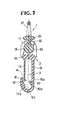
- Figures 1 through 3 show a swivel snap hook which comprises an eye member 1 adapted to be attached to one end of a carrying strap (not shown) of a bag such as a shoulder bag, and a hook member 2 rotatably and rockably connected to the eye member 1.
- the eye and hook members 1, 2 are molded of synthetic resin in a manner described below.
- the hook member 2 has a first base 10, a hook body 12 extending downwardly from a lower side of the first base 10, and a planar closure tongue 13 extending downwardly from the lower side of the first base 10 so as to normally close the hook body 12 in a manner described below.
- the hook member 2 also has an integral bearing portion which extends upwardly from an upper side of the first base 10 and which is divided into a pair of opposed bearing halves 11, 11 by a space 15.
- the pair of opposed bearing halves 11, 11 have a pair of aligned through-holes 16, 16 of circular cross section communicating with the space 15.
- the eye member 1 has a second base 20, a ring-shaped portion 21 extending upwardly from the second base 20, and an integral arm portion 22 extending downwardly from the second base 20 remotely from the ring-shaped portion 21 into the space 15 and terminating in an enlarged end 23 loosely received in the through-holes 16,16 in the bearing halves 11, 11 across the space 15.
- the arm portion 22 has a circular cross section of a diameter slightly smaller than the width of the space 15 ( Figure 2), while the enlarged end 23 of the arm portion 22 is in the shape of a remainder of a sphere in which an upper segmental part has been cut off by a plane perpendicular to the axis 3 of the arm portion 22.
- the diameter of this sphere is larger than the width of the space 15 and is substantially equal to the diameter of the through-holes 16, 16.
- the hook member 2 is rotatable on the eye member 1 about the axis 3 of the arm portion 22 and is pivotally movable on the eye member 1 about the spherical enlarged end 23 in a plane which includes the axis 3 of the bearing portion and which is parallel to the bearing halves 11, 11.
- the hook body 12 has a substantially straight stem portion 12b projecting perpendicularly from the base 10, and a hook-shaped portion 12b extending substantially perpendicularly from a lower end of the stem portion 12a and terminating in an upwardly directed free end 18.
- the hook-shaped portion 12c has on its inner curved surface adjacent to the free end 18 a reinforcing rib 17 which serves to prevent the hook-shaped portion 12b from being objectionably deformed due to undue stress exerted thereon.
- the closure tongue 13 extends downwardly from the base 10 in parallel relation to the stem portion 12b of the hook body 12 and terminates in a free end 19 which, as the closure tongue 13 is in free form, is disposed inwardly of the free end 18 of the hook body 12 with a relatively small gap 14 therebetween.
- the closure tongue 13 is depressed inwardly against its resilience by a ring-shaped article (not shown) to be threaded onto the hook body 12
- the free end 14 of the closure tongue 13 is spaced wider from the free end 18 of the hook-shaped portion 12c to open the hook body 12 so that the article is allowed to be threaded onto the hook body 12.
- the closure tongue 13 restores the shape of Figures 1 and 3 under its resilience to close the hook body 12, thus preventing the article from being removed from the hook body 12.
- the free end 19 of the closure tongue 13 is bent inwardly, i.e. toward the stem portion 12b of the hook body 12.
- the hook body 12 has a projection 30 extending inwardly (toward the closure tongue 13) from the stem portion 12b.
- the projection 30 is disposed slightly below the bent end 19 of the closure tongue 13 so as not to interfere therewith when the closure tongue 13 is depressed to assume the phantom-line position of Figure 1.
- the projection 30 has a concave under-surface 30a as an extension of an arcuate inner surface of the hook-shaped portion 12c, and the reinforcement rib 17 also has a concave surface 17a as an extension of the arcuate inner surface of the hook-shaped portion 12c.
- These two concave surfaces 30a, 17a are a pair of diametrically opposed parts of the circumference of a circle having a radius r.
- the bent end 19 of the closure tongue 13, as the latter is in free form, is horizontally (in Figures 1 and 3) spaced apart from the projection 30 by a distance L1 substantially equal to the radius r.
- the projection 30 has a height L2 equal to the distance L3 between an outer surface of the closure tongue 13 and a tip of the bent end 19.
- the reinforcement rib 17 is in the shape of a generally equilateral triangle having an apex in which the concave surface 17a terminates; this apex is horizontally ( Figures 1 and 3) spaced apart from a tip of the projection 30 by a distance L4 slightly larger than the radius r.
- the inwardly bent end 19 of the closure tongue 13 and the projection 30 of the hook body 2 jointly serve to restrict upward movement of a ring-shaped article (not shown) threaded onto the hook-shaped portion 12c. Since the free end 19 of the closure tongue 13 is inwardly bent, the amount of deformation of the closure tongue 13 is reduced so that the closure tongue 13 is prevented from being excessively depressed and hence broken particularly at its foot portion about which the closure tongue 13 is angularly moved when the ring-shaped article is threaded onto and removed from the hook body 12.
- the concave under-surface 30a of the projection 30 extends as an extension of the arcuate inner surface of the hook-shaped portion 12c and hence serves as a guide to assist in removing the ring-shaped article from the hook-shaped portion 12c.
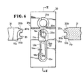
- the eye member 1 and the hook member 2 are molded on a mold simultaneously in a single molding step in coupled or assembled state.
- the mold includes a pair of identical molding die halves 30, 30, and a pair of identical associated molding rods 31, 31.
- the two molding die halves 30, 30 have a pair of symmetrical first recesses 21a, 21a for forming the ring-shaped portion 21 a of the eye member 1 (of a prospective swivel snap hook), a pair of symmetrical second recesses 20a, 20a for forming a part of the first base 20 of the eye member 1, a pair of symmetrical third recesses 10a, 10a for forming a part of the bearing halves 11a, 11a, a pair of symmetrical fourth recesses 10a, 10b for forming a part of the second base 10 of the hook member 2, a pair of symmetrical fifth recesses 12a, 12a for forming a hook body 12, a pair of symmetrical sixth recesses 13a, 13a for forming the closure tongue 13, and a pair of symmetrical seventh recesses 23a, 23a for forming a part of the spherical enlarged end 23 of the arm portion 22.
- the sixth recess 13a for the closure tongue 13 extends downwardly from the fourth recess 10a for the second base 10 and terminates in a free end 19a disposed adjacent to an upwardly directed free end 18a of the fifth recess 12a for the hook body 12 and spaced inwardly therefrom by a relatively small distance 14a corresponding to the gap 14 ( Figures 1 and 3).
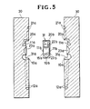
- the pair of the associated molding rods 31 have in their confronting ends a pair of symmetrical eighth recesses 20b, 20b for forming the remaining part of the first base 20 of the eye member 1, a pair of symmetrical ninth recesses 22b, 22b for forming the arm portion 22, a pair of symmetrical tenth recesses 23b, 23b for forming the remaining part of the spherical enlarged end 23 of the arm portion 22, a pair of symmetrical eleventh recess 10b, 10b for forming the remaining part of the second base 10 of the hook member 2, and two pairs of symmetrical twelfth recesses 11 b, 11 b; 11b, 11b for forming the remaining part of the bearing halves 11, 11 of the hook member 1.
- the two molding die halves 30, 30 have a pair of symmetrical thirteenth recesses 31a, 31a for jointly receiving the two associated molding rods 31, 31 during molding.
- the mold is closed, namely, the two molding die halves 30, 30 are put together in such a manner that the first, second, third, fourth, fifth, sixth, seventh and thirteenth recesses 21a, 20a, 11a, 10a, 12a, 13a, 23a, 31a in one molding die half 30 are in registry with the corresponding recesses in the other molding die half 30.
- Each associated molding rod 31 is inserted into the pair of symmetrical thirteenth recesses 31a, 31a halfway in such a manner that the two associated molding rods 31, 31 abut each other on their confronting ends at the center line 3a ( Figure 4) of the second, third, fourth and seventh recesses 20a, 11a, 10a, 23a.
- thermoplastic synthetic resin is then injected through a sprue 32 ( Figure 4) into the closed mold to fill the mold cavity thereof.
- a sprue 32 Figure 4
- the thermoplastic material filled in the mold cavity is cooled to become hard enough
- the molded article is removed from the mold by parting the molding die halves 30, 30 and the associated molding rods 31,31, as is well known in the art.
- the eye member 1 and the hook member 2 have been simultaneously in coupled or assembled state, at which time a free end 19 of the freshly molded closure tongue 13 is disposed inwardly of a free end 18 of the freshly molded hook body 12 with a relatively small gap 14a therebetween. Accordingly it is possible to obtain the final product, i.e. the swivel snap hook of Figures 1-3 in only a single molding step with no additional step of bringing the free end 19 of the closure tongue 13 inwardly of the free end 18 of the hook body 12 after the hook has been molded. The overall process for manufacturing this swivel snap hook is quite simplified and hence much less costly.
Landscapes
- Engineering & Computer Science (AREA)
- General Engineering & Computer Science (AREA)
- Mechanical Engineering (AREA)
- Manufacturing & Machinery (AREA)
- Hooks, Suction Cups, And Attachment By Adhesive Means (AREA)
- Moulds For Moulding Plastics Or The Like (AREA)
- Slide Fasteners, Snap Fasteners, And Hook Fasteners (AREA)
Claims (7)
Applications Claiming Priority (4)
| Application Number | Priority Date | Filing Date | Title |
|---|---|---|---|
| JP142991/84 | 1984-07-10 | ||
| JP14299184A JPS6122805A (ja) | 1984-07-10 | 1984-07-10 | 合成樹脂製のなす環及びその製造方法 |
| JP1984105998U JPS6121327U (ja) | 1984-07-13 | 1984-07-13 | 合成樹脂製のなす環 |
| JP105998/84U | 1984-07-13 |
Publications (2)
| Publication Number | Publication Date |
|---|---|
| EP0170811A1 EP0170811A1 (de) | 1986-02-12 |
| EP0170811B1 true EP0170811B1 (de) | 1988-12-28 |
Family
ID=26446207
Family Applications (1)
| Application Number | Title | Priority Date | Filing Date |
|---|---|---|---|
| EP85106729A Expired EP0170811B1 (de) | 1984-07-10 | 1985-05-31 | Kunststoff-Karabinerhaken und Verfahren zu seiner Herstellung |
Country Status (11)
| Country | Link |
|---|---|
| US (1) | US4665592A (de) |
| EP (1) | EP0170811B1 (de) |
| KR (1) | KR860002128B1 (de) |
| AU (1) | AU555071B2 (de) |
| BR (1) | BR8503297A (de) |
| CA (1) | CA1281170C (de) |
| DE (1) | DE3567070D1 (de) |
| GB (1) | GB2161534B (de) |
| HK (1) | HK61190A (de) |
| MY (1) | MY100272A (de) |
| SG (1) | SG58190G (de) |
Families Citing this family (43)
| Publication number | Priority date | Publication date | Assignee | Title |
|---|---|---|---|---|
| CH667968GA3 (de) * | 1987-05-11 | 1988-11-30 | ||
| USD308241S (en) | 1987-07-06 | 1990-05-29 | Underberg John T | Exchangeable fishing sinker |
| JPH0424967Y2 (de) * | 1987-07-16 | 1992-06-15 | ||
| DE3725352A1 (de) * | 1987-07-30 | 1989-02-09 | United Carr Gmbh Trw | Gelenkverbindung zwischen zwei kunststoffteilen |
| US5092018A (en) * | 1989-03-20 | 1992-03-03 | Seron Suren V | Lanyard construction |
| US5027477A (en) * | 1989-03-20 | 1991-07-02 | Seron Manufacturing Company | Break away lanyard |
| US4908913A (en) * | 1989-08-01 | 1990-03-20 | Yoshida Kogyo K.K. | Safety hook |
| FR2652749A1 (fr) * | 1989-10-06 | 1991-04-12 | Salomon Sa | Mousqueton d'accrochage. |
| JPH0583435U (ja) * | 1992-04-20 | 1993-11-12 | 吉田工業株式会社 | ナス環 |
| US5475901A (en) * | 1992-09-18 | 1995-12-19 | National Molding Corporation | Swivelling snaphook |
| ES2090917T3 (es) * | 1992-10-09 | 1996-10-16 | Faure Bertrand Automobile | Grapa de fijacion amovible y pivotante de maniobra manual, y dispositivo de conexion que lo incluye. |
| FR2696796B1 (fr) * | 1992-10-09 | 1995-01-13 | Faure Bertrand Automobile | Clip de fixation amovible et pivotante à manÓoeuvre manuelle, et dispositif de liaison le comportant, notamment pour assise de siège de véhicule. |
| US5253396A (en) * | 1993-01-22 | 1993-10-19 | Royalox International Inc. | Snap hook assembly |
| JPH06300030A (ja) * | 1993-04-13 | 1994-10-25 | Yoshida Kogyo Kk <Ykk> | ナス環 |
| DE4338900A1 (de) * | 1993-04-23 | 1994-10-27 | Turck P C Gmbh & Co Kg | Haltevorrichtung für Schlauch- und andere Leitungen an medizinischen Einrichtungen sowie im Bereich der Kranken- und Altenpflege |
| JPH072625U (ja) * | 1993-04-30 | 1995-01-13 | ワイケイケイ株式会社 | ナス環 |
| USD354433S (en) | 1993-06-11 | 1995-01-17 | National Molding Corporation | Snaphook |
| US5441225A (en) * | 1993-10-18 | 1995-08-15 | Hall; Larry D. | Webbing clamp and resilient hoop apparatus and method |
| USD402189S (en) | 1994-05-23 | 1998-12-08 | Ykk Corporation | Swivel hook |
| JP3269941B2 (ja) * | 1995-07-20 | 2002-04-02 | ワイケイケイ株式会社 | ナス環 |
| USD375889S (en) | 1995-12-29 | 1996-11-26 | Miller Debra L | Christmas ornament swivel |
| GB9602732D0 (en) * | 1996-02-10 | 1996-04-10 | Driver Melvin B | Lead attachment device |
| JP2001025403A (ja) * | 1999-05-11 | 2001-01-30 | Ykk Corp | 合成樹脂製ナス環 |
| US6539588B1 (en) * | 1999-10-04 | 2003-04-01 | Comprehensive Identification Products, Inc. | Breakaway lanyard with adjustable mounting element |
| JP2001304231A (ja) * | 2000-04-27 | 2001-10-31 | Ykk Corp | 合成樹脂製ナス環 |
| US7013497B1 (en) | 2002-03-15 | 2006-03-21 | Athletic Specialties, Inc. | Strap-securing device |
| USD472452S1 (en) | 2002-06-20 | 2003-04-01 | An-Chuan Chou | Hook |
| USD500244S1 (en) | 2002-11-13 | 2004-12-28 | Nifco Inc. | Hook |
| USD484393S1 (en) | 2003-05-08 | 2003-12-30 | Ming S. Chang | Mechanical cable snap |
| US20060239770A1 (en) * | 2004-12-30 | 2006-10-26 | Liu Le C | Swivel coupling device for coupling assembly |
| US20080141499A1 (en) * | 2006-12-19 | 2008-06-19 | San Jiang Duo Co., Ltd. | Hook forming method |
| TWM341125U (en) * | 2008-02-19 | 2008-09-21 | Feng-Jia Liang | Pivot device of hook |
| US8365461B2 (en) * | 2010-04-16 | 2013-02-05 | Centro Corporation | Long line fishing connector |
| USD675806S1 (en) * | 2010-08-11 | 2013-02-12 | Jeffrey Caul | Handkerchief accessory |
| US9814300B2 (en) * | 2010-11-30 | 2017-11-14 | Monty James Webster | Clip-on earplug case |
| USD649024S1 (en) * | 2010-12-17 | 2011-11-22 | Ykk Corporation | Swivel hook |
| USD668579S1 (en) * | 2011-08-16 | 2012-10-09 | D B Industries, Inc. | Buckle portion |
| USD671447S1 (en) * | 2012-01-05 | 2012-11-27 | Nerison Sr Robert N | Tie down buckle |
| CN105188454B (zh) * | 2013-05-08 | 2018-03-20 | Ykk株式会社 | 连结件和钩构件 |
| WO2017048846A1 (en) * | 2015-09-14 | 2017-03-23 | OptikTechnik LLC | Optical sensing device and method in a liquid treatment system |
| US10165840B2 (en) | 2017-02-04 | 2019-01-01 | I Amika Adams | Locking fastener system |
| US20240295238A1 (en) * | 2021-06-29 | 2024-09-05 | Ykk Corporation | Rotary Connecting Structure, Rotary Connecting Tool, and Method for Configuring Rotary Connecting Structure |
| USD1030458S1 (en) * | 2022-04-26 | 2024-06-11 | Wenzhou Yuanfei Pet Toy Products Co., Ltd. | Pet leash clip |
Citations (1)
| Publication number | Priority date | Publication date | Assignee | Title |
|---|---|---|---|---|
| EP0099577A1 (de) * | 1982-07-23 | 1984-02-01 | Nippon Notion Kogyo Co., Ltd. | Drehhakenvorrichtung |
Family Cites Families (24)
| Publication number | Priority date | Publication date | Assignee | Title |
|---|---|---|---|---|
| US548694A (en) * | 1895-10-29 | Snap-hdok | ||
| US307280A (en) * | 1884-10-28 | Snap-hook | ||
| US750373A (en) * | 1903-09-16 | 1904-01-26 | Blanch T Kinnear | Trace-hook. |
| FR380083A (fr) * | 1907-07-20 | 1907-11-28 | Victor Drollon | Double crochet porte-mousqueton |
| US1059812A (en) * | 1912-02-06 | 1913-04-22 | Jefferson Barry | Snap-hook. |
| US1744344A (en) * | 1928-08-23 | 1930-01-21 | Sullivan Simon | Snap construction |
| US1804377A (en) * | 1930-02-18 | 1931-05-05 | North & Judd Mfg Co | Snap hook with swivel |
| US2033766A (en) * | 1933-11-01 | 1936-03-10 | George W Hall | Connecting link |
| US2217052A (en) * | 1938-02-23 | 1940-10-08 | George W Hall | Hook |
| US2532674A (en) * | 1946-10-21 | 1950-12-05 | Magnus O Nelsen | Clothespin |
| GB655947A (en) * | 1947-09-17 | 1951-08-08 | Richard Garrett Engineering Wo | Improvements in or relating to electric space heaters |
| DE934567C (de) * | 1952-08-17 | 1955-10-27 | Maerklin & Cie G M B H Geb | Verfahren zum Herstellen von Gehaeuseteilen od. dgl. von Spielzeugen aus nicht aushaertbarem Kunststoff im Giess- und Pressverfahren |
| CH401370A (de) * | 1962-06-02 | 1965-10-31 | Isabel Gmbh | Verfahren und Spritzmaschine zur Kettenherstellung |
| DE1963102A1 (de) * | 1968-12-26 | 1970-07-09 | Nat Lead Co | Verfahren zur Herstellung von komplizierten Spritzgussstuecken |
| US3719974A (en) * | 1971-03-04 | 1973-03-13 | R Abrams | Integral one-piece key ring or locking ring |
| US3825012A (en) * | 1973-04-13 | 1974-07-23 | H Nicoll | Reusable umbilical cord clamp for veterinary use |
| DE2528903C3 (de) * | 1975-06-28 | 1979-03-01 | F. & G. Hachtel, 7080 Aalen | Verfahren, spritzgegossener Rollring und Spritzgießform zur Herstellung eines Rollringes für Gardinenschienen |
| DE2626748C3 (de) * | 1976-06-15 | 1979-10-11 | Daimler-Benz Ag, 7000 Stuttgart | Abheftklammer |
| US4064604A (en) * | 1976-08-24 | 1977-12-27 | Hartman George F | Swivels |
| US4212303A (en) * | 1978-07-17 | 1980-07-15 | Hollister Incorporated | Umbilical cord clamp |
| FR2465114A1 (fr) * | 1979-09-07 | 1981-03-20 | Eisler Robert | Sandow muni de crochets, ainsi que procede et outil pour la fabrication d'un tel sandow |
| GB2099066B (en) * | 1981-05-15 | 1985-04-03 | Hago Prod Ltd | Hook |
| US4415281A (en) * | 1981-11-23 | 1983-11-15 | United Technologies Corporation | Hydrodynamic fluid film bearing |
| SE8303180L (sv) * | 1982-06-10 | 1983-12-11 | Illinois Tool Works | Hake |
-
1985
- 1985-05-16 KR KR1019850003362A patent/KR860002128B1/ko not_active Expired
- 1985-05-22 GB GB08512890A patent/GB2161534B/en not_active Expired
- 1985-05-27 CA CA000482410A patent/CA1281170C/en not_active Expired - Fee Related
- 1985-05-31 EP EP85106729A patent/EP0170811B1/de not_active Expired
- 1985-05-31 DE DE8585106729T patent/DE3567070D1/de not_active Expired
- 1985-06-06 AU AU43361/85A patent/AU555071B2/en not_active Ceased
- 1985-07-03 US US06/751,430 patent/US4665592A/en not_active Expired - Fee Related
- 1985-07-04 BR BR8503297A patent/BR8503297A/pt not_active IP Right Cessation
-
1987
- 1987-08-12 MY MYPI87001303A patent/MY100272A/en unknown
-
1990
- 1990-07-17 SG SG581/90A patent/SG58190G/en unknown
- 1990-08-09 HK HK611/90A patent/HK61190A/xx unknown
Patent Citations (1)
| Publication number | Priority date | Publication date | Assignee | Title |
|---|---|---|---|---|
| EP0099577A1 (de) * | 1982-07-23 | 1984-02-01 | Nippon Notion Kogyo Co., Ltd. | Drehhakenvorrichtung |
Also Published As
| Publication number | Publication date |
|---|---|
| GB2161534A (en) | 1986-01-15 |
| AU4336185A (en) | 1986-01-16 |
| BR8503297A (pt) | 1986-04-01 |
| HK61190A (en) | 1990-08-17 |
| MY100272A (en) | 1990-07-28 |
| EP0170811A1 (de) | 1986-02-12 |
| US4665592A (en) | 1987-05-19 |
| GB8512890D0 (en) | 1985-06-26 |
| SG58190G (en) | 1990-09-07 |
| AU555071B2 (en) | 1986-09-11 |
| DE3567070D1 (en) | 1989-02-02 |
| KR860002128B1 (ko) | 1986-12-11 |
| CA1281170C (en) | 1991-03-12 |
| GB2161534B (en) | 1988-09-21 |
| KR860000841A (ko) | 1986-02-20 |
Similar Documents
| Publication | Publication Date | Title |
|---|---|---|
| EP0170811B1 (de) | Kunststoff-Karabinerhaken und Verfahren zu seiner Herstellung | |
| EP0159614B1 (de) | Kunstharz-Drehgelenk-Karabinerhaken und sein Herstellungsverfahren | |
| EP0158351B1 (de) | Kunstharz-Drehgelenk-Karabinerhaken | |
| EP0664406B1 (de) | Aus Kunstharz geformte Gurtanschlussvorrichtung und Verfahren zu deren Herstellung | |
| KR100331379B1 (ko) | 합성 수지제 스위벌 후크 | |
| US5840351A (en) | Golf ball-forming mold | |
| US4988472A (en) | Method of inserting a piece into a mold for molding a mouth of a preform | |
| KR910005337B1 (ko) | 슬라이드 파스너용 슬라이더 견인탭 | |
| GB2058901A (en) | Elastic Strap Provided with a Hook | |
| CA2357098A1 (en) | Tamper-indicating closure with resilient locking projections | |
| US5526954A (en) | Injection molded plastic bucket with an integrally moulded carry handle | |
| EP0939693B1 (de) | Spritzform zur herstellung eines eimers mit schwenkbarem handgriff | |
| US5503309A (en) | Toggle dispensing closure wherein the toggle is attached to the closure by a pair of opposing slots | |
| US4799288A (en) | Pivot bush | |
| US6574839B2 (en) | Swivel snap hook of synthetic resin | |
| US4760714A (en) | Artefact band with bonded clasp | |
| US4489849A (en) | Pivot assembly | |
| JPS6039241Y2 (ja) | キヤツプの射出成形用金型 | |
| US4242788A (en) | Method of disassembling hooks from hook retainers in recessed cups of fishing lures | |
| JPS634813Y2 (de) | ||
| CA1057920A (en) | Apparatus and method for moulding plastics covers for containers | |
| JP2556437B2 (ja) | 提げ手形成用テープ | |
| JPH07156206A (ja) | 射出成形金型 | |
| HK1010747B (en) | Molded synthetic resin belt connecting device and method of producing the same | |
| JPH08328079A (ja) | 樹脂製シャッタ羽根及びその製造方法 |
Legal Events
| Date | Code | Title | Description |
|---|---|---|---|
| PUAI | Public reference made under article 153(3) epc to a published international application that has entered the european phase |
Free format text: ORIGINAL CODE: 0009012 |
|
| AK | Designated contracting states |
Designated state(s): BE CH DE FR IT LI NL SE |
|
| 17P | Request for examination filed |
Effective date: 19860516 |
|
| 17Q | First examination report despatched |
Effective date: 19870709 |
|
| GRAA | (expected) grant |
Free format text: ORIGINAL CODE: 0009210 |
|
| AK | Designated contracting states |
Kind code of ref document: B1 Designated state(s): BE CH DE FR IT LI NL SE |
|
| ITF | It: translation for a ep patent filed | ||
| REF | Corresponds to: |
Ref document number: 3567070 Country of ref document: DE Date of ref document: 19890202 |
|
| ET | Fr: translation filed | ||
| PLBE | No opposition filed within time limit |
Free format text: ORIGINAL CODE: 0009261 |
|
| STAA | Information on the status of an ep patent application or granted ep patent |
Free format text: STATUS: NO OPPOSITION FILED WITHIN TIME LIMIT |
|
| 26N | No opposition filed | ||
| ITTA | It: last paid annual fee | ||
| PGFP | Annual fee paid to national office [announced via postgrant information from national office to epo] |
Ref country code: FR Payment date: 19940420 Year of fee payment: 10 |
|
| PGFP | Annual fee paid to national office [announced via postgrant information from national office to epo] |
Ref country code: CH Payment date: 19940517 Year of fee payment: 10 |
|
| PGFP | Annual fee paid to national office [announced via postgrant information from national office to epo] |
Ref country code: NL Payment date: 19940531 Year of fee payment: 10 Ref country code: DE Payment date: 19940531 Year of fee payment: 10 |
|
| EAL | Se: european patent in force in sweden |
Ref document number: 85106729.8 |
|
| PGFP | Annual fee paid to national office [announced via postgrant information from national office to epo] |
Ref country code: SE Payment date: 19950214 Year of fee payment: 11 |
|
| PGFP | Annual fee paid to national office [announced via postgrant information from national office to epo] |
Ref country code: BE Payment date: 19950302 Year of fee payment: 11 |
|
| PG25 | Lapsed in a contracting state [announced via postgrant information from national office to epo] |
Ref country code: LI Effective date: 19950531 Ref country code: CH Effective date: 19950531 |
|
| PG25 | Lapsed in a contracting state [announced via postgrant information from national office to epo] |
Ref country code: NL Effective date: 19951201 |
|
| REG | Reference to a national code |
Ref country code: CH Ref legal event code: PL |
|
| NLV4 | Nl: lapsed or anulled due to non-payment of the annual fee |
Effective date: 19951201 |
|
| PG25 | Lapsed in a contracting state [announced via postgrant information from national office to epo] |
Ref country code: DE Effective date: 19960201 |
|
| PG25 | Lapsed in a contracting state [announced via postgrant information from national office to epo] |
Ref country code: FR Effective date: 19960229 |
|
| REG | Reference to a national code |
Ref country code: FR Ref legal event code: ST |
|
| REG | Reference to a national code |
Ref country code: FR Ref legal event code: ST |
|
| PG25 | Lapsed in a contracting state [announced via postgrant information from national office to epo] |
Ref country code: BE Effective date: 19960531 |
|
| PG25 | Lapsed in a contracting state [announced via postgrant information from national office to epo] |
Ref country code: SE Effective date: 19960601 |
|
| BERE | Be: lapsed |
Owner name: NIPPON NOTION KOGYO CO. LTD Effective date: 19960531 |
|
| EUG | Se: european patent has lapsed |
Ref document number: 85106729.8 |