EP0174001A2 - Appareil pour le forgeage de pièces par fluage - Google Patents
Appareil pour le forgeage de pièces par fluage Download PDFInfo
- Publication number
- EP0174001A2 EP0174001A2 EP85111076A EP85111076A EP0174001A2 EP 0174001 A2 EP0174001 A2 EP 0174001A2 EP 85111076 A EP85111076 A EP 85111076A EP 85111076 A EP85111076 A EP 85111076A EP 0174001 A2 EP0174001 A2 EP 0174001A2
- Authority
- EP
- European Patent Office
- Prior art keywords
- pressure
- die
- members
- work
- roller
- Prior art date
- Legal status (The legal status is an assumption and is not a legal conclusion. Google has not performed a legal analysis and makes no representation as to the accuracy of the status listed.)
- Withdrawn
Links
Images


Classifications
-
- B—PERFORMING OPERATIONS; TRANSPORTING
- B21—MECHANICAL METAL-WORKING WITHOUT ESSENTIALLY REMOVING MATERIAL; PUNCHING METAL
- B21K—MAKING FORGED OR PRESSED METAL PRODUCTS, e.g. HORSE-SHOES, RIVETS, BOLTS OR WHEELS
- B21K23/00—Making other articles
-
- B—PERFORMING OPERATIONS; TRANSPORTING
- B21—MECHANICAL METAL-WORKING WITHOUT ESSENTIALLY REMOVING MATERIAL; PUNCHING METAL
- B21J—FORGING; HAMMERING; PRESSING METAL; RIVETING; FORGE FURNACES
- B21J13/00—Details of machines for forging, pressing, or hammering
- B21J13/02—Dies or mountings therefor
-
- B—PERFORMING OPERATIONS; TRANSPORTING
- B21—MECHANICAL METAL-WORKING WITHOUT ESSENTIALLY REMOVING MATERIAL; PUNCHING METAL
- B21J—FORGING; HAMMERING; PRESSING METAL; RIVETING; FORGE FURNACES
- B21J5/00—Methods for forging, hammering, or pressing; Special equipment or accessories therefor
- B21J5/008—Incremental forging
-
- B—PERFORMING OPERATIONS; TRANSPORTING
- B21—MECHANICAL METAL-WORKING WITHOUT ESSENTIALLY REMOVING MATERIAL; PUNCHING METAL
- B21J—FORGING; HAMMERING; PRESSING METAL; RIVETING; FORGE FURNACES
- B21J5/00—Methods for forging, hammering, or pressing; Special equipment or accessories therefor
- B21J5/02—Die forging; Trimming by making use of special dies ; Punching during forging
Definitions
- the invention relates to an apparatus for forming a shaped part from a work. It includes two members spaced away from one another at a settable distance and defining a pressure zone thererebetween, holder means for maintaining the setting of the aforesaid distance, first and second die means clamping the work therebetween, roller means, including a plurality of rollers in operative contact with one of the members for transporting at least one of the die means along a transport direction, and along a direction opposite thereto, and wherein the members have an inclination to one another so as to cause the pressure zone to converge along the transport direction, and drive means for driving the die means along the roller means to the pressure zone and away therefrom.
- One of the die means includes a plurality of adjoining pressure elements, and each pressure-transferring element has a pressure-transfer surface on one end thereof facing the roller means, and a molding surface on the other end thereof determining at least partly the shape of the part.
- the pressure-transferring elements move in the transport direction, and also toward the other member while being transported through the pressure zone.
- the shaped part is obtained from the work by a gradually and smoothly increasing pressure being applied to the work by the members during the transport of the die means through the pressure zone.
- a part-forming apparatus makes it possible to fabricate large forgings in a precise manner not feasible by conventional forging methods, and additionally at a considerable saving in the energy expended to produce such forgings.
- U.S. patent 3,847,004 there is known an apparatus for applying pressure, which includes a pressure base, pressure means vertically spaced above the pressure base to define a pressure zone, means for conveying work between the pressure base and the pressure means, and wherein one of the pressure base and the pressure means is inclined in the direction the work is conveyed. Rollers convert sliding friction into rolling friction as the work passes through the pressure zone, and means are provided for guiding the rollers as they pass under the pressure zone.
- An auxiliary pressure unit is adjustably mounted on the pressure means; additionally guide means are provided for the rollers as they pass under the pressure means, as well as adjusting means for adjusting the guide means to compensate for movement between the pressure means and the auxiliary pressure unit.
- the Bringewald '004 patent has, however, several disadvantages, which are not overcome even by considering the Bringewald '004 patent in conjunction with one or several of the secondary references.
- a principal disadvantage is the fact the rollers are linked together by the links, so as to form a chain, which in turn, has peaks and valleys on an outer surface thereof.
- slippage occurs between the work support and the lower chain, if the upper front edge of the frontmost force-translating element happens to lodge in one of the valleys, thus restraining any forward movement of the force-translating elements. This slippage cannot be eliminated if the work support is transported forwardly at a greater pull, or force.
- Such a non-uniform pressure causes the part to be formed with some deformities, at best resulting in non-uniform parts shaped by the apparatus according to Bringewald; thus a part made during one run does not necessarily resemble a part made during another run of the Bringewald apparatus.
- This and other objects of the invention are attained by providing self-adjustable matching means interposed between the member defining an inclination with the transport direction and the other member, which defines, in turn, together with the inclination-defining member, a pressure zone.
- pressure transfer from the top member to the work is smoothed and maximized, resulting, in turn, in a more uniform and speedier production of shaped parts.
- Slippage is further eliminated by implementing the drive of the dies in the form of a hydraulically operated cylinder-piston mechanism, which replaces the slippage-prone chain of the prior art.
- each pressure-transferring element By the pressure-transfer surface of each pressure-transferring element being concave, as viewed in the transport direction, and by the convex rod surface of each longitudinal rod of the matching means being in contact with the concave pressure-transfer surface of a corresponding pressure-transferring element, a large load- bearing surface is obtained, permitting, in turn, a longer life-span of the die. This contrasts favorably with the line contact of the prior art, which may be changed under large pressures to an indeterminate surface contact.
- Figs. 1, 2 and 3 illustrating the overall plan view, overall elevation view, and side view of the inventive apparatus, respectively; an additional preheating station is denoted by A, while a work-loading and heating station B, a part-forming station C, and a die-release station D will best be seen in Figs. 1, 2 and 3.
- a work 10 for example in the form of a blank, best seen in Fig. 16, is normally first heated in the preheating station or material oven A to a predetermined temperature, which is about 700-900°F in the case of aluminum. It should be noted that it is also possible to dispense with the preheating station A, and to heat the work 10 only in the die oven 12. In the open position of the die oven 12, an oven chamber 18 will be seen to be lifted by a conventional chain-and-sprocket mechanism 20, not further described in detail.
- the die assembly implemented, for example, as clamping means for holding the work 10, will already have been placed in the die oven 12.
- the die assembly, or die means will be seen to consist of upper die means 24, and lower die means 26, as shown, for example, in Fig. 4.
- the upper die means will be seen to consist of a plurality of plugs or pressure-transferring elements 28.
- Each pressure-transferring element 28 is formed on a normally upper and thereof with a generally concave pressure transfer surface 30, and a lower molding surface 32, which actually comes into contact with the part to be formed from the work 10. Facing an inclined roller chain 110 of a top member 78, there are disposed on each pressure-transferring element 28, alternately referred to as a male plug 28, self-adjusting matching means, for example, in the form of a longitudinal rod 34.
- Each longitudinal rod 34 has a substantially semi-spherical cross-section, so as to define a plane rod surface and a convex rod surface.
- Each rod 34 cooperates with a corresponding pressure-transferring element or male plug 28 so as to nestle therein facing a corresponding pressure-transfer surface 30, while facing the roller chain 110 of the top member 78 with the plane rod surface.
- each rod 34 is constrained to pivot about an axis substantially in the plane rod surface, so that the plane rod surface abuts the roller chain 110 of the top member 78 opposite the plane rod surface.
- the purpose of the self-adjustable matching means or rods 34 is to maximize pressure transfer from the top member 78 to the pressure surface 30, by each rod 34 automatically adjusting its position in response to the inclination of roller chain 110 of the top member 78, so that a gradually increasing pressure is applied to the work 10 from the top member 78 through the action of the inclined plane on the roller chain 110, the rods 34 and the pressure-transferring elements or male plugs 28, in order to obtain the shaped part.
- the mechanism by means of which the top member 78 applies pressure to the pressure surface 30 will be discussed later.
- the lower die means or female portion of the die 26, as best seen in Fig. 4, consists substantially of a container 36, formed at the rear part or upstream portion thereof, as seen in the direction of transportation, with a wedge-shaped part 38, having an inner rear wall 39, and an inner front wall 41.
- One end plug of the plugs 28 normally abuts the rear wall 39, while the other end plug of the plugs 28 is normally spaced from the front wall 41.
- Plug holding or restraining means take the form, for example, of a wedge 42 cooperating with another wedge 46.
- the wedge 42 abuts the other end plug 28 with a first major surface thereof; the second major surface of the wedge 42 is transverse to the longitudinal direction of the container 36, and converges with the first major surface in a direction away from the bottom of the container 36.
- the wedge 46 abuts with one major surface thereof the other major surface of the wedge 42, while the other major surface of the wedge 42 converges with the one major surface portion of the wedge 46 in a direction transverse to the longitudinal direction of the container 36, and towards the bottom of the container 36.
- Tightening means 40 are mounted on the container 36 near the other end plug, and are constrained to move in the longitudinal direction of the container 36, so that upon actuation of the tightening means 40 in a predetermined sense, the plugs or pressure-transferring elements 28 are tightened to one another.
- the tightening means 40 may consist, for example, of an L-shaped member 44, which has a normally horizontally projecting arm connected with a free end thereof to the other major surface of the wedge 46, and is formed with a threaded opening 48.
- a normally vertically positioned minor arm abuts with a free end portion thereof the rim of the container 38, and a bolt 50, which is threaded along a middle portion thereof, is normally engaged in the threaded opening 48.
- An upper end of the bolt 50 is formed with a head 51, and the other end of the bolt 50 is held in the container 38, so as to be freely rotatable therein. Consequently, when the bolt 50 is rotated in a predetermined sense, normally clockwise, the wedge 42 exerts a gradually increasing pressure on the other end male plug 28.
- Each male plug 28 is formed with lateral projections 52, preferably in the form of cylindrically formed projections, which are provided so as to enable die separation means, to be described hereinafter, and best seen in Fig 11 and 12, to separate the upper die means 24, for example in the form of an assembly of male plugs 28, from the lower, or female die means 26.
- each projection 52 is surrounded by a rotatable collar 53, which is arranged to make contact with the die separation means.
- the pressure zone lies between a roller chain 110 of the top member or pressure unit 78, as seen in Fig. 2, and a base member 81 best seen in Fig. 2, on which there are disposed roller means, such as a roller conveyor 22.
- the top member or pressure unit 78 is provided with holder means or distance-adjusting means for selectably adjusting and maintaining the distance between the top member 78 and a base member 81, as best seen in Fig. 2.
- a platform 84 above plate 83 is formed with four openings 86, through which pass four threaded screws 88, respectively, on which there are threaded nuts 64 welded to sprocket wheels 89, respectively, and linking means, for example a chain 90, operatively links the four sprocket wheels 89.
- the non-threaded openings 86 formed in the platform 84 communicate with respective slots 85.
- a drive sprocket 92, driven by the motor 82, is also linked up with the chain 90 as shown, for example, in Fig. 7, so that the plate 83, the motor 82 mounted on an upper platen 91, and the nuts 64 located between the platform 83 and the upper platen 91, can be made to move up and down, depending on the sense of rotation of the motor 82.
- a frame 94 seen for example, in Figs. 6 and 7, is secured to the upper platen 91, which, in turn, is provided with tension adjusting means, such as a tensioning mechanism, shown in greater detail in Figs. 8, 9, and 10.
- Brackets 96 project outwardly from the frame 94 near one corner thereof.
- the brackets 96 are pivoted to the frame 94 about an axle 98 and carry on it pulleys 100.
- a connecting plate 102 To each bracket 96 there is secured a connecting plate 102, which in turn, is formed with a threaded opening 104.
- a threaded bolt 106 which is freely rotatable in the connecting plate 102, passes through a threaded opening 104. Consequently the pulleys 100 can be moved further outwardly from the frame 94, or moved further inwardly by rotating the threaded bolt 106 counterclockwise, or clockwise, respectively.
- Freely rotatable rollers or pulleys 108 are mounted near the other two corners of the frame 94.
- Roller means such as a combination of an endless roller cable 113 and chain 110 pass around the pulleys 100 on top and the rollers 108 at the bottom, and its tension is adjustable by the aforesaid tensioning mechanism.
- the frontmost lower roller 108 is at a lower elevation, as seen in Fig. 6, than the rearmost lower roller 108, thus causing the roller means in the form of the roller chain 110, and consequently the pressure zone to converge along the transport direction of the work.
- the tension of the roller chain 110 and of the cable 113 is adjustable by a turnbuckle 111, best seen in Fig. 6, which links the roller chain 110 to a cable 113, the chain 110 and the cable 113 forming an endless loop.
- the pressure zone will now be seen defined as extending between the roller conveyor 110, (which is located on an upper level, and is inclined to the transport direction), and the roller conveyor 22, being located on the lower level.
- the die assembly including the upper die means 24, and the lower die means 26, is forcibly pulled forwardly by the piston 72, it comes in contact with the inclined plane, implemented by the roller chain 110.
- the die assembly, and particularly the upper die means 24, extends along a substantially horizontal plane before entering the pressure zone. However, upon entering the pressure zone, the die assembly is forced to align itself with the inclined plane. This results in the familiar action and reaction phenomenon, namely the top member 78 causes each male plug 28 to be gradually and successively pressed onto the work 10 in the form of a blank plate.
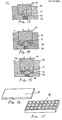
- Fig. 13 where the work 10, originally shaped as a blank shown in Fig. 16, will be seen to be shaped into a part 14, best seen in Fig. 17, as the work 10 will have been molded between the upper male plugs 28 and a stripping plate 112 placed on an inner bottom of the container 36 of the lower die means, and wherein each male plug 28 has been provided with a flat operating surface.
- Figs. 14 and 15 there are illustrated alternate ways of shaping the part 10 seen to be a shaped part 15 in Fig. 14, and a shaped part 13 in Fig. 15, by making use of segmented male plugs 28.
- each male plug 28 is provided, for example, with three prongs 29, which serve, for example, to form cavities in the work 10, which is to be formed into a part, into separate open-ended chambers.
- the segmented male plugs 28 are disposed below the work 10, while male plugs 28, which have each a flat operating surface, are placed above the work 10.
- Fig. 15 segmented male plugs 28 are used on the top side of the work 10 and a one piece female die portion 115 is used on the bottom side.
- Each projection 52 extending from a male plug 28, Fig. 11, is surrounded by a roller 53, freely rotatable thereon. This feature reduces friction when the upper male plugs are separated from the female or lower die by the die separation means discussed earlier.
- rollers of the roller conveyors 22 and 110 rotate and thus greatly reduce any friction that would otherwise be created by a fixed inclined plane and the high pulling force developed by the driving force of the piston assembly, in the absence of any rollers.
- the die means holding the now shaped part 14 are made to enter a die release station D, seen, for example, on the right-hand side of Figs. 1 and 2.
- the die release station D is provided with die separating means in the form of longitudal wedges 116 secured to rails 116', and interposed, on one hand, between the projections 52, extending on each side or a male plug zb, ana on the other hand, the upper rim of the container 36 of the lower die means 26.
- the transport action of the piston 72 thus results in the male plugs 26 being lifted out of the lower die means, or female die 26, and providing free access to the shaped part 14.
- the die oven 12 While the part is being formed, and also during the time period the formed part 14 is returned to the home position, the die oven 12 is made to travel away from the loading position and the parallel support or base member 80 is raised to support the lower conveyor roller 22, on which the female die 26 is travelling.
- the roller conveyor 22, which carries the female die 26, which, in turn, contains the shaped part 14 comes to rest on the parallel support plate, or base member 80. Thereafter the connecting pin 76 is withdrawn from the piston rod 74.
Landscapes
- Engineering & Computer Science (AREA)
- Mechanical Engineering (AREA)
- Forging (AREA)
Applications Claiming Priority (2)
| Application Number | Priority Date | Filing Date | Title |
|---|---|---|---|
| US06/647,900 US4608848A (en) | 1984-09-06 | 1984-09-06 | Part forming apparatus by flow forging |
| US647900 | 1984-09-06 |
Publications (2)
| Publication Number | Publication Date |
|---|---|
| EP0174001A2 true EP0174001A2 (fr) | 1986-03-12 |
| EP0174001A3 EP0174001A3 (fr) | 1987-10-14 |
Family
ID=24598707
Family Applications (1)
| Application Number | Title | Priority Date | Filing Date |
|---|---|---|---|
| EP85111076A Withdrawn EP0174001A3 (fr) | 1984-09-06 | 1985-09-03 | Appareil pour le forgeage de pièces par fluage |
Country Status (4)
| Country | Link |
|---|---|
| US (1) | US4608848A (fr) |
| EP (1) | EP0174001A3 (fr) |
| JP (1) | JPS61199539A (fr) |
| CA (1) | CA1220652A (fr) |
Cited By (2)
| Publication number | Priority date | Publication date | Assignee | Title |
|---|---|---|---|---|
| EP0334976A1 (fr) * | 1984-09-06 | 1989-10-04 | Joseph J. Mele | Appareil pour façonner des pièces métalliques par fluo-forgeage et former des tôles métalliques à l'aide de matériau élastique |
| WO1999012674A1 (fr) * | 1997-09-11 | 1999-03-18 | Dean Lutz | Procede de production d'un article |
Families Citing this family (11)
| Publication number | Priority date | Publication date | Assignee | Title |
|---|---|---|---|---|
| US4770020A (en) * | 1984-09-06 | 1988-09-13 | Mele Joseph J | Part-shaping apparatus by flow forging and sheet-metal rubber forming |
| JPS61193821A (ja) * | 1985-02-22 | 1986-08-28 | Fanuc Ltd | 射出成形機の型締装置 |
| US6179607B1 (en) * | 1988-07-08 | 2001-01-30 | Fanuc Ltd | Two-platen mold-clamping apparatus |
| US4907436A (en) * | 1988-10-11 | 1990-03-13 | Efco, Inc. | Step forging press |
| US5595082A (en) * | 1995-01-19 | 1997-01-21 | Gandara Systems | Sheet metal corrugator |
| US5673581A (en) * | 1995-10-03 | 1997-10-07 | Segal; Vladimir | Method and apparatus for forming thin parts of large length and width |
| US6757976B2 (en) * | 2002-02-04 | 2004-07-06 | Asa Co. Ltd. | Method for manufacturing alloy wheel for automobile |
| US7018137B2 (en) * | 2004-06-30 | 2006-03-28 | Omega Tools, Inc. | Apparatus and process for installing “T” couplings on underground pipe |
| US8028558B2 (en) * | 2007-10-31 | 2011-10-04 | Segal Vladimir M | Method and apparatus for forming of panels and similar parts |
| US9308574B1 (en) * | 2014-12-15 | 2016-04-12 | Joseph Mele | Net shape forging press and system |
| CN118635422A (zh) * | 2024-07-11 | 2024-09-13 | 河北康百特电力科技有限公司 | 一种多工位热模锻压力机及加工工艺 |
Family Cites Families (11)
| Publication number | Priority date | Publication date | Assignee | Title |
|---|---|---|---|---|
| US850810A (en) * | 1906-02-14 | 1907-04-16 | William P Worth | Tube or bar straightening machine. |
| US2657009A (en) * | 1951-09-07 | 1953-10-27 | Edgar C Alexander | Jack |
| US2701485A (en) * | 1954-02-04 | 1955-02-08 | Smith Corp A O | Draw roll blank gripping apparatus |
| US3233444A (en) * | 1962-06-26 | 1966-02-08 | Rockwell Standard Co | Taper roll machine and method |
| GB1011279A (en) * | 1963-04-16 | 1965-11-24 | Atlas Copco Ab | Improvement in feeding device working in stepwise manner for a rock drill |
| US3303833A (en) * | 1964-09-21 | 1967-02-14 | Aubrey B Melling | Valve tappet |
| US3521472A (en) * | 1967-02-03 | 1970-07-21 | Bringewald Process Corp | Process and apparatus for the production of parts from ductile materials with integral stiffeners on one or both sides |
| US3490261A (en) * | 1967-04-03 | 1970-01-20 | Gen Motors Corp | Method and apparatus for producing tapered leaf springs |
| GB1266277A (fr) * | 1970-11-03 | 1972-03-08 | ||
| US3847004A (en) * | 1971-03-25 | 1974-11-12 | Bringewald Process Corp | Apparatus and method for applying pressure and die and method for forming a part |
| BG28890A1 (en) * | 1979-05-14 | 1980-12-12 | Paunov | Method for plastic material processing |
-
1984
- 1984-09-06 US US06/647,900 patent/US4608848A/en not_active Expired - Fee Related
-
1985
- 1985-09-03 CA CA000489866A patent/CA1220652A/fr not_active Expired
- 1985-09-03 EP EP85111076A patent/EP0174001A3/fr not_active Withdrawn
- 1985-09-06 JP JP60198400A patent/JPS61199539A/ja active Granted
Cited By (2)
| Publication number | Priority date | Publication date | Assignee | Title |
|---|---|---|---|---|
| EP0334976A1 (fr) * | 1984-09-06 | 1989-10-04 | Joseph J. Mele | Appareil pour façonner des pièces métalliques par fluo-forgeage et former des tôles métalliques à l'aide de matériau élastique |
| WO1999012674A1 (fr) * | 1997-09-11 | 1999-03-18 | Dean Lutz | Procede de production d'un article |
Also Published As
| Publication number | Publication date |
|---|---|
| US4608848A (en) | 1986-09-02 |
| CA1220652A (fr) | 1987-04-21 |
| JPH0346210B2 (fr) | 1991-07-15 |
| JPS61199539A (ja) | 1986-09-04 |
| EP0174001A3 (fr) | 1987-10-14 |
Similar Documents
| Publication | Publication Date | Title |
|---|---|---|
| EP0174001A2 (fr) | Appareil pour le forgeage de pièces par fluage | |
| KR910007294B1 (ko) | 프레스식 슬래브폭 감소방법 및 장치 | |
| KR102023176B1 (ko) | 빌렛 절단장치 | |
| US5673581A (en) | Method and apparatus for forming thin parts of large length and width | |
| US3847004A (en) | Apparatus and method for applying pressure and die and method for forming a part | |
| US4770020A (en) | Part-shaping apparatus by flow forging and sheet-metal rubber forming | |
| US5001918A (en) | Method and apparatus for making blanks of a profile varying lengthwise | |
| SU1207390A3 (ru) | Способ поперечной гибки профилированного или продольно-гофрированного листового металла и устройство дл его осуществлени | |
| US7237417B2 (en) | Roll preshaping | |
| US3969919A (en) | Workpiece feed channel | |
| EP0334976A1 (fr) | Appareil pour façonner des pièces métalliques par fluo-forgeage et former des tôles métalliques à l'aide de matériau élastique | |
| JPS5835777B2 (ja) | アプセツタ | |
| US3668910A (en) | Extrusion handling apparatus | |
| JPS5836422Y2 (ja) | アプセツタ | |
| CN108838684A (zh) | 实心棒料全自动制管生产线 | |
| US5778719A (en) | Method of stretch-forming a channel material | |
| JP3350132B2 (ja) | 金属板幅圧下方法 | |
| JP3200816B2 (ja) | 半溶融金属成形機の材料供給装置 | |
| JP2581184B2 (ja) | 水平対向形鍛造プレスのローラテーブル装置 | |
| JP3182022B2 (ja) | 金属板幅圧下装置および金属板幅圧下方法 | |
| JP2615865B2 (ja) | 鍛造プレス装置 | |
| RU2041007C1 (ru) | Способ изготовления стержневых изделий с фланцем на торце и буртом в средней части и устройство для его осуществления | |
| US1921210A (en) | Offsetting press | |
| US731486A (en) | Apparatus for making axles, shafts, &c. | |
| SU763019A1 (ru) | Установка дл правки |
Legal Events
| Date | Code | Title | Description |
|---|---|---|---|
| PUAI | Public reference made under article 153(3) epc to a published international application that has entered the european phase |
Free format text: ORIGINAL CODE: 0009012 |
|
| AK | Designated contracting states |
Kind code of ref document: A2 Designated state(s): DE FR GB IT SE |
|
| PUAL | Search report despatched |
Free format text: ORIGINAL CODE: 0009013 |
|
| AK | Designated contracting states |
Kind code of ref document: A3 Designated state(s): DE FR GB IT SE |
|
| 17P | Request for examination filed |
Effective date: 19880109 |
|
| 17Q | First examination report despatched |
Effective date: 19880310 |
|
| STAA | Information on the status of an ep patent application or granted ep patent |
Free format text: STATUS: THE APPLICATION IS DEEMED TO BE WITHDRAWN |
|
| 18D | Application deemed to be withdrawn |
Effective date: 19910403 |