EP0174474A1 - Trennmittelauftragsvorrichtung - Google Patents
Trennmittelauftragsvorrichtung Download PDFInfo
- Publication number
- EP0174474A1 EP0174474A1 EP85109229A EP85109229A EP0174474A1 EP 0174474 A1 EP0174474 A1 EP 0174474A1 EP 85109229 A EP85109229 A EP 85109229A EP 85109229 A EP85109229 A EP 85109229A EP 0174474 A1 EP0174474 A1 EP 0174474A1
- Authority
- EP
- European Patent Office
- Prior art keywords
- applicator
- release agent
- housing
- pressing
- section
- Prior art date
- Legal status (The legal status is an assumption and is not a legal conclusion. Google has not performed a legal analysis and makes no representation as to the accuracy of the status listed.)
- Withdrawn
Links
- 239000003795 chemical substances by application Substances 0.000 claims abstract description 30
- 229920002313 fluoropolymer Polymers 0.000 claims abstract description 11
- 239000004811 fluoropolymer Substances 0.000 claims abstract description 10
- -1 polytetrafluoroethylene Polymers 0.000 claims description 6
- 239000007787 solid Substances 0.000 claims description 6
- 229920001343 polytetrafluoroethylene Polymers 0.000 claims description 5
- 239000004810 polytetrafluoroethylene Substances 0.000 claims description 5
- 238000010438 heat treatment Methods 0.000 claims 1
- 229920002545 silicone oil Polymers 0.000 description 8
- 238000005470 impregnation Methods 0.000 description 4
- 238000000034 method Methods 0.000 description 3
- 239000011148 porous material Substances 0.000 description 3
- 239000004734 Polyphenylene sulfide Substances 0.000 description 2
- 238000001125 extrusion Methods 0.000 description 2
- 238000012986 modification Methods 0.000 description 2
- 230000004048 modification Effects 0.000 description 2
- 239000002245 particle Substances 0.000 description 2
- 229920001707 polybutylene terephthalate Polymers 0.000 description 2
- 229920000069 polyphenylene sulfide Polymers 0.000 description 2
- 238000010186 staining Methods 0.000 description 2
- 238000010276 construction Methods 0.000 description 1
- 230000001186 cumulative effect Effects 0.000 description 1
- 239000000463 material Substances 0.000 description 1
- 239000002184 metal Substances 0.000 description 1
- 230000002093 peripheral effect Effects 0.000 description 1
- 239000004033 plastic Substances 0.000 description 1
- 230000000717 retained effect Effects 0.000 description 1
- 239000000126 substance Substances 0.000 description 1
Images

Classifications
-
- G—PHYSICS
- G03—PHOTOGRAPHY; CINEMATOGRAPHY; ANALOGOUS TECHNIQUES USING WAVES OTHER THAN OPTICAL WAVES; ELECTROGRAPHY; HOLOGRAPHY
- G03G—ELECTROGRAPHY; ELECTROPHOTOGRAPHY; MAGNETOGRAPHY
- G03G15/00—Apparatus for electrographic processes using a charge pattern
- G03G15/20—Apparatus for electrographic processes using a charge pattern for fixing, e.g. by using heat
- G03G15/2003—Apparatus for electrographic processes using a charge pattern for fixing, e.g. by using heat using heat
- G03G15/2014—Apparatus for electrographic processes using a charge pattern for fixing, e.g. by using heat using heat using contact heat
- G03G15/2017—Structural details of the fixing unit in general, e.g. cooling means, heat shielding means
- G03G15/2025—Structural details of the fixing unit in general, e.g. cooling means, heat shielding means with special means for lubricating and/or cleaning the fixing unit, e.g. applying offset preventing fluid
-
- G—PHYSICS
- G03—PHOTOGRAPHY; CINEMATOGRAPHY; ANALOGOUS TECHNIQUES USING WAVES OTHER THAN OPTICAL WAVES; ELECTROGRAPHY; HOLOGRAPHY
- G03G—ELECTROGRAPHY; ELECTROPHOTOGRAPHY; MAGNETOGRAPHY
- G03G2215/00—Apparatus for electrophotographic processes
- G03G2215/20—Details of the fixing device or porcess
- G03G2215/2093—Release agent handling devices
- G03G2215/2096—Release agent handling devices using porous fluoropolymers for wicking the release agent
Definitions
- the present invention relates to devices for applying a release agent, and more particularly to devices for applying a release agent in fixing devices of plain paper copiers and facsimiles.
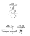
- FIGURES 1, 2A and 2B it is conventional in a plain paper copier or a facsimile to fix a toner image 10 on a sheet 12 by passing sheet 12 between an elastic roller 14 and a fixing roller 16 heated by heater 18.
- a release agent usually silicone oil
- Conventional release agent applicators may include either a heat-resistant felt 20 impregnated with the release agent as shown in FIGURE 1 or a porous polytetrafluoroethylene tube 22 filled with release agent 28 as shown in FIGURES 2A and 2B.
- a layer 24 of material that closes pores in tube 22 surrounds all of tube 22 except the portion that contacts fixing roller 16.
- Tube 22 may be carried by a support plate 26. Either of these applicators may be of the disposable type.
- Heat resistant felt applicator 20, illustrated in FIGURE 1 has a relatively short life (i.e., only about 10,000 copies are obtained from a fixing roll fed with the release agent by applicator 20). Toner or paper particles deposited on the felt surface either prevent further application of the silicone oil or damage the surface of the fixing roller. Also, the amount of oil applied in the initial period is so great as to cause frequent staining of the copy paper.
- FIGURES 2A and 2B The overall shape and construction of the porous tube applicator illustrated in FIGURES 2A and 2B are complex because this applicator requires its peripheral portion to be masked, its two ends to be sealed, and the provision of air vents. Also, oil leakage may occur during transportation or storage of the applicator or upon standing after it is set in the copier.
- the present invention eliminates these problems associated with conventional release agent applicators.
- the applicator of the present invention includes a solid, or non-hollow, porous body of a fluoropolymer that is impregnated with a release agent.
- the porous body may have a round, rectangular or triangular cross section. The body applies release agent by being pressed against the fixing roller.
- the present invention enables simple and uniform application of the release agent.
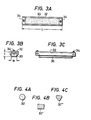
- an applicator in accordance with one embodiment of this invention includes a solid, or non-hollow, porous body 30 of a fluoropolymer such as polytetrafluoroethylene ("Poreflon" of Sumitomo Electric Industries, Ltd.) set in a housing 32 which serves as a support member.
- Housing 32 is made of metal or a heat-resistant plastic (polyphenylene sulfide (PPS), or polybutylene terephthalate (PBT)).
- Porous body 30 of fluoropolymer is impregnated with a release agent such as silicone oil.
- porous fluropolymer body 30 is secured to housing 32 by bolts 34 or other suitable means.
- porous body 30 may be impregnated with release agent prior to or after being set in housing 32.
- Porous body 30 is fabricated by extrusion techniques and may be provided with a variety of cross-sectional shapes such as shown in FIGURES 4A - 4C, depending upon the shape of the extrusion die used.
- the porosity of body 30 is preferably in the range of 25 - 85%.
- the viscosity of the release agent typically silicone oil, may preferably be in the range of 500 - 100,000 cs depending upon the required amount of oil to be applied. The more preferred viscosity range is from 1,000 to 50,000 cs.
- the oil may be impregnated in body 30 by simply submerging it in the oil. If quick impregnation is desired, the oil may be heated or placed in a vacuum atmosphere.
- Fixing roller 16 in FIGURE 5 had such a rotating speed as to process 12 sheets of paper (21 cm x 29.7 cm) per minute.
- Applicator 40 in accordance with the present invention was pressed against fixing roller 16 by leaf spring 42 attached to heater cover 44.
- Paper guide 13 guided paper between rollers 16 and 14.
- the release agent applicator in accordance with the present invention is advantageous in that it has a very long service life and can be used virtually permanently by repeating the impregnation with silicone oil. Also it applies a uniform and small quantity of the oil from the beginning to the end of service. No oil staining of the copy paper occurs in the initial period of application.
- the applicator has a simple configuration and oil is retained in the pores in the fluoropolymer by capillary action, so no oil leak will occur during trans- portion or storage, or even upon standing after setting the device in the fixing apparatus.
Landscapes
- Physics & Mathematics (AREA)
- General Physics & Mathematics (AREA)
- Fixing For Electrophotography (AREA)
- Coating Apparatus (AREA)
Applications Claiming Priority (2)
| Application Number | Priority Date | Filing Date | Title |
|---|---|---|---|
| JP183024/84 | 1984-08-31 | ||
| JP18302484A JPS6161663A (ja) | 1984-08-31 | 1984-08-31 | 離型剤塗布装置 |
Publications (1)
| Publication Number | Publication Date |
|---|---|
| EP0174474A1 true EP0174474A1 (de) | 1986-03-19 |
Family
ID=16128402
Family Applications (1)
| Application Number | Title | Priority Date | Filing Date |
|---|---|---|---|
| EP85109229A Withdrawn EP0174474A1 (de) | 1984-08-31 | 1985-07-23 | Trennmittelauftragsvorrichtung |
Country Status (2)
| Country | Link |
|---|---|
| EP (1) | EP0174474A1 (de) |
| JP (1) | JPS6161663A (de) |
Cited By (6)
| Publication number | Priority date | Publication date | Assignee | Title |
|---|---|---|---|---|
| EP0240834A1 (de) * | 1986-04-11 | 1987-10-14 | Siemens Aktiengesellschaft | Einrichtung zum Heissfixieren von Tonerbildern aus thermoplastischem Tonermaterial |
| WO1993008512A1 (en) * | 1991-10-26 | 1993-04-29 | W.L. Gore & Associates (Uk) Limited | Oil transfer component |
| WO1995009385A1 (en) * | 1993-09-28 | 1995-04-06 | W.L. Gore & Associates, Inc. | Improved release agent supply wick for printer apparatus and method for making and using same |
| GB2285768A (en) * | 1994-01-19 | 1995-07-26 | Gore & Ass | Layered oil transfer component |
| EP0661610A3 (de) * | 1993-12-29 | 1996-03-06 | Fuji Xerox Co Ltd | Fixiergerät für ein Bilderzeugungsgerät. |
| US6143675A (en) * | 1995-06-07 | 2000-11-07 | W. L. Gore & Associates (Uk) Ltd. | Porous composite |
Families Citing this family (1)
| Publication number | Priority date | Publication date | Assignee | Title |
|---|---|---|---|---|
| JP2581963B2 (ja) * | 1987-08-24 | 1997-02-19 | 富士写真フイルム株式会社 | 直接ポジ画像形成方法 |
Citations (2)
| Publication number | Priority date | Publication date | Assignee | Title |
|---|---|---|---|---|
| DE3016098A1 (de) * | 1979-04-28 | 1980-11-13 | Canon Kk | Fixiervorrichtung |
| GB2093769A (en) * | 1981-02-19 | 1982-09-08 | Sumitomo Electric Industries | Fixing toner images |
-
1984
- 1984-08-31 JP JP18302484A patent/JPS6161663A/ja active Pending
-
1985
- 1985-07-23 EP EP85109229A patent/EP0174474A1/de not_active Withdrawn
Patent Citations (2)
| Publication number | Priority date | Publication date | Assignee | Title |
|---|---|---|---|---|
| DE3016098A1 (de) * | 1979-04-28 | 1980-11-13 | Canon Kk | Fixiervorrichtung |
| GB2093769A (en) * | 1981-02-19 | 1982-09-08 | Sumitomo Electric Industries | Fixing toner images |
Non-Patent Citations (4)
| Title |
|---|
| PATENTS ABSTRACTS OF JAPAN, vol. 6, no. 156 (P-135)[1034], 17th August 1982; & JP - A - 57 72 172 (CANON K.K.) 06-05-1982 * |
| PATENTS ABSTRACTS OF JAPAN, vol. 6, no. 252 (P-161)[1130], 10th December 1982; & JP - A - 57 147 674 (SUMITOMO DENKI KOGYO K.K.) 11-09-1982 * |
| PATENTS ABSTRACTS OF JAPAN, vol. 6, no. 51 (P-108)[929], 6th April 1982; & JP - A - 56 165 176 (CANON K.K.) 18-12-1981 * |
| PATENTS ABSTRACTS OF JAPAN, vol. 7, no. 67 (P-184)[1212], 19th March 1983; & JP - A - 57 211 179 (RICOH K.K.) 24-12-1982 * |
Cited By (11)
| Publication number | Priority date | Publication date | Assignee | Title |
|---|---|---|---|---|
| EP0240834A1 (de) * | 1986-04-11 | 1987-10-14 | Siemens Aktiengesellschaft | Einrichtung zum Heissfixieren von Tonerbildern aus thermoplastischem Tonermaterial |
| WO1993008512A1 (en) * | 1991-10-26 | 1993-04-29 | W.L. Gore & Associates (Uk) Limited | Oil transfer component |
| WO1995009385A1 (en) * | 1993-09-28 | 1995-04-06 | W.L. Gore & Associates, Inc. | Improved release agent supply wick for printer apparatus and method for making and using same |
| US5478423A (en) * | 1993-09-28 | 1995-12-26 | W. L. Gore & Associates, Inc. | Method for making a printer release agent supply wick |
| US5690739A (en) * | 1993-09-28 | 1997-11-25 | W. L. Gore & Associates, Inc. | Release agent supply wick for printer apparatus and method for making and using same |
| US5709748A (en) * | 1993-09-28 | 1998-01-20 | W. L. Gore & Associates, Inc. | Release agent supply wick for printer apparatus |
| EP0661610A3 (de) * | 1993-12-29 | 1996-03-06 | Fuji Xerox Co Ltd | Fixiergerät für ein Bilderzeugungsgerät. |
| US5619315A (en) * | 1993-12-29 | 1997-04-08 | Fuji Xerox Co., Ltd. | Fixing apparatus using a coated elastic member for use in an image forming apparatus |
| GB2285768A (en) * | 1994-01-19 | 1995-07-26 | Gore & Ass | Layered oil transfer component |
| GB2285768B (en) * | 1994-01-19 | 1997-09-17 | Gore & Ass | Layered oil transfer component |
| US6143675A (en) * | 1995-06-07 | 2000-11-07 | W. L. Gore & Associates (Uk) Ltd. | Porous composite |
Also Published As
| Publication number | Publication date |
|---|---|
| JPS6161663A (ja) | 1986-03-29 |
Similar Documents
| Publication | Publication Date | Title |
|---|---|---|
| EP0616271B1 (de) | Flüssigkeits Dosier- und Auftragegerät | |
| US6117528A (en) | Oil delivery sheet material for use in various printer devices | |
| EP0174474A1 (de) | Trennmittelauftragsvorrichtung | |
| US4375201A (en) | Fixing apparatus | |
| US4287280A (en) | Release agent applicators and method of applying release agent emulsions upon fusers in electrostatic copiers | |
| GB2093769A (en) | Fixing toner images | |
| US4668537A (en) | Method and apparatus for applying a releasing agent | |
| JPH04257885A (ja) | 剥離剤取扱装置 | |
| GB2261400B (en) | Oil transfer component | |
| US5659869A (en) | Image fixing apparatus having pressure roller with fluorine surface active agent | |
| JPS62178992A (ja) | 複写機用オイル塗布機構 | |
| EP0126414B1 (de) | Trennmittelauftragsvorrichtung für ein Kopiergerät | |
| US4633805A (en) | Release agent applicator for copying machine | |
| JPH07191567A (ja) | 熱圧力ローラ及び定着装置 | |
| EP0126418A2 (de) | Trennmittelauftragseinrichtung für ein Kopiergerät | |
| JPS63123076A (ja) | 離型剤塗布装置 | |
| EP0855631A3 (de) | Fixieranordnung und Herstellungsverfahren für eine darin verwendete Reinigungsklinge | |
| JPH01237583A (ja) | 定着用回転体の周面クリーニング装置 | |
| EP0131849B1 (de) | Ablösmittel-Antragvorrichtung für Kopiergerät | |
| JPH0451900Y2 (de) | ||
| JPH0548203Y2 (de) | ||
| JPS61103179A (ja) | 離型剤塗布装置 | |
| JPH06274063A (ja) | 定着オイル塗布装置およびこれに用いる定着オイル塗布パッドの製造方法 | |
| JPS63123077A (ja) | 離型剤塗布装置 | |
| JPH0850426A (ja) | 画像形成装置の定着装置 |
Legal Events
| Date | Code | Title | Description |
|---|---|---|---|
| PUAI | Public reference made under article 153(3) epc to a published international application that has entered the european phase |
Free format text: ORIGINAL CODE: 0009012 |
|
| AK | Designated contracting states |
Kind code of ref document: A1 Designated state(s): DE GB IT |
|
| 17P | Request for examination filed |
Effective date: 19860425 |
|
| 17Q | First examination report despatched |
Effective date: 19870806 |
|
| STAA | Information on the status of an ep patent application or granted ep patent |
Free format text: STATUS: THE APPLICATION IS DEEMED TO BE WITHDRAWN |
|
| 18D | Application deemed to be withdrawn |
Effective date: 19880802 |
|
| RIN1 | Information on inventor provided before grant (corrected) |
Inventor name: KATO, CHIAKIC/O KUMATORI WORKS Inventor name: MATSUDA, AKIOC/O KUMATORI WORKS Inventor name: OGINO, TAKAOC/O KUMATORI WORKS |