EP0178446A1 - Dispositif de hacheur à semi-conducteur - Google Patents
Dispositif de hacheur à semi-conducteur Download PDFInfo
- Publication number
- EP0178446A1 EP0178446A1 EP85111298A EP85111298A EP0178446A1 EP 0178446 A1 EP0178446 A1 EP 0178446A1 EP 85111298 A EP85111298 A EP 85111298A EP 85111298 A EP85111298 A EP 85111298A EP 0178446 A1 EP0178446 A1 EP 0178446A1
- Authority
- EP
- European Patent Office
- Prior art keywords
- semiconductor
- suction
- load
- control device
- inductive
- Prior art date
- Legal status (The legal status is an assumption and is not a legal conclusion. Google has not performed a legal analysis and makes no representation as to the accuracy of the status listed.)
- Granted
Links
- 239000004065 semiconductor Substances 0.000 title claims abstract description 79
- 230000001939 inductive effect Effects 0.000 claims abstract description 33
- 230000005284 excitation Effects 0.000 claims description 17
- 238000010079 rubber tapping Methods 0.000 claims description 3
- 230000008033 biological extinction Effects 0.000 claims 1
- 230000015572 biosynthetic process Effects 0.000 claims 1
- 239000002689 soil Substances 0.000 claims 1
- 239000003990 capacitor Substances 0.000 description 5
- 238000004804 winding Methods 0.000 description 4
- 238000010586 diagram Methods 0.000 description 2
- 230000010355 oscillation Effects 0.000 description 2
- 230000001172 regenerating effect Effects 0.000 description 2
- 230000002123 temporal effect Effects 0.000 description 2
- 230000008878 coupling Effects 0.000 description 1
- 238000010168 coupling process Methods 0.000 description 1
- 238000005859 coupling reaction Methods 0.000 description 1
- 230000003111 delayed effect Effects 0.000 description 1
- 238000009499 grossing Methods 0.000 description 1
- 238000007790 scraping Methods 0.000 description 1
- 210000000582 semen Anatomy 0.000 description 1
Images


Classifications
-
- H—ELECTRICITY
- H02—GENERATION; CONVERSION OR DISTRIBUTION OF ELECTRIC POWER
- H02M—APPARATUS FOR CONVERSION BETWEEN AC AND AC, BETWEEN AC AND DC, OR BETWEEN DC AND DC, AND FOR USE WITH MAINS OR SIMILAR POWER SUPPLY SYSTEMS; CONVERSION OF DC OR AC INPUT POWER INTO SURGE OUTPUT POWER; CONTROL OR REGULATION THEREOF
- H02M3/00—Conversion of DC power input into DC power output
- H02M3/02—Conversion of DC power input into DC power output without intermediate conversion into AC
- H02M3/04—Conversion of DC power input into DC power output without intermediate conversion into AC by static converters
- H02M3/10—Conversion of DC power input into DC power output without intermediate conversion into AC by static converters using discharge tubes with control electrode or semiconductor devices with control electrode
- H02M3/145—Conversion of DC power input into DC power output without intermediate conversion into AC by static converters using discharge tubes with control electrode or semiconductor devices with control electrode using devices of a triode or transistor type requiring continuous application of a control signal
- H02M3/155—Conversion of DC power input into DC power output without intermediate conversion into AC by static converters using discharge tubes with control electrode or semiconductor devices with control electrode using devices of a triode or transistor type requiring continuous application of a control signal using semiconductor devices only
- H02M3/156—Conversion of DC power input into DC power output without intermediate conversion into AC by static converters using discharge tubes with control electrode or semiconductor devices with control electrode using devices of a triode or transistor type requiring continuous application of a control signal using semiconductor devices only with automatic control of output voltage or current, e.g. switching regulators
- H02M3/158—Conversion of DC power input into DC power output without intermediate conversion into AC by static converters using discharge tubes with control electrode or semiconductor devices with control electrode using devices of a triode or transistor type requiring continuous application of a control signal using semiconductor devices only with automatic control of output voltage or current, e.g. switching regulators including plural semiconductor devices as final control devices for a single load
- H02M3/1584—Conversion of DC power input into DC power output without intermediate conversion into AC by static converters using discharge tubes with control electrode or semiconductor devices with control electrode using devices of a triode or transistor type requiring continuous application of a control signal using semiconductor devices only with automatic control of output voltage or current, e.g. switching regulators including plural semiconductor devices as final control devices for a single load with a plurality of power processing stages connected in parallel
-
- Y—GENERAL TAGGING OF NEW TECHNOLOGICAL DEVELOPMENTS; GENERAL TAGGING OF CROSS-SECTIONAL TECHNOLOGIES SPANNING OVER SEVERAL SECTIONS OF THE IPC; TECHNICAL SUBJECTS COVERED BY FORMER USPC CROSS-REFERENCE ART COLLECTIONS [XRACs] AND DIGESTS
- Y02—TECHNOLOGIES OR APPLICATIONS FOR MITIGATION OR ADAPTATION AGAINST CLIMATE CHANGE
- Y02T—CLIMATE CHANGE MITIGATION TECHNOLOGIES RELATED TO TRANSPORTATION
- Y02T10/00—Road transport of goods or passengers
- Y02T10/60—Other road transportation technologies with climate change mitigation effect
- Y02T10/72—Electric energy management in electromobility
Definitions
- the invention relates to a control device for a circuit arrangement in which a load is fed from a DC voltage source via a semiconductor plate, which contains a parallel connection of two controllable semiconductor valves with the same forward direction, wherein a device for generating clock frequency signals is provided in the current path in the control device each semiconductor valve has an inductive resistor on the output side, the input-side connection point of the semiconductor valves is connected to a pole of the DC voltage source and the connection point of the inductive resistors is connected to a pole of the load, the connection points of the semiconductor valves with the inductive resistors are each connected via a free-wheeling diode to the other pole of the load are connected, and the control device is designed such that two formed by 180 0 electrically shifted clock signals, each the upper an actuator w supplied to the semiconductor valves so earth that they are opened and closed alternately offset by 180 0 .
- Transistors or thystors are used as semiconductor valves.
- the inductive resistors which are not coupled to one another, cause a delayed current rise and fall, so that the current ripple caused by the clocking is reduced.
- a much higher voltage is present at the capacitor and thus at the load resistor than at the input of the semiconductor valves.
- the voltage across the capacitor and the load resistor has a ripple of twice the frequency of the pulse frequency.
- a DC-DC converter in which a load via a semiconductor actuator, which contains a parallel connection of two controllable semiconductor valves in the same forward direction, is fed from a DC voltage source.
- a device for generating clock frequency signals is provided in such a way that the Semiconductor valves can be opened and closed alternately offset by 180 °.
- the semiconductor valves are connected on the output side to an autotransformer with center tap, the connection point on the input side of the semiconductor valves being connected to a pole of the DC voltage source and the center tap being connected to a pole of a load resistor.
- the connection points of the semiconductor valves with the autotransformer are each connected to the other pole of the load via a diode.
- the load is embodied by an ohmic amplifier, as is e.g. is the case in electronic switching systems of exchanges, remote control devices or computers.
- Transistors whose control voltages are derived from windings coupled to the autotransformer are used as semiconductor valves. The two transistors are alternately opened and closed by 180 °, so that a DC voltage composed of half-waves is present at the consumer, which results from the temporal addition of the voltage blocks.
- This DC voltage applied to the consumer has half the value of the battery voltage applied to the DC-DC converter and is not complete.
- the autotransformer of the known DC-DC converter thus acts as a symmetrical voltage divider for the applied battery voltage. Control of the voltage or current applied to the consumer is not provided. With this known DC-DC converter, an inductive or ohmic load in the power cannot be controlled.
- a drive system controlled by a microprocessor in which a DC motor is controlled from a battery via a transistor.
- a freewheeling diode is connected in parallel with the DC motor.
- a further transistor with a further free-floating diode is provided.
- the invention has for its object the ripple in a control device of the type mentioned. to further reduce the load current on a load which is controllable in terms of power and has a small inductance and to effectively reduce the noise caused by the pulsing at the load.
- the inductive resistors are formed by a suction transformer with center tap
- the device for generating clock frequency signals has a setpoint generator for specifying the pulse-pause ratio
- parallel another semiconductor actuator of the same design is arranged to the semiconductor actuator and the center taps of the suction transformers of the two semiconductor actuators are connected to the ends of a third suction transformer with center taps, the center taps of the third suction transformer being connected to a pole of the inductive load and that the control device is designed in such a way that it produces with the same modulation depth for the Halbleterventile clock signals, respectively, but which are electrically offset from each other for the two parallel circuits 90 0th
- the clock frequency at the inductive load is quadrupled and the current vibration range is reduced to about 1/16, so that the tonal structure-borne noise components of the pulse frequency and the weight and volume of the entire device can be kept significantly lower than in the known designs.
- the inductive load is designed as a DC motor
- the motor can be operated in several speed ranges by maintaining a constant modulation of the semiconductor valves in steps of at least approximately 0.25, 0.5, 0.75 or 1 while maintaining a DC voltage at the armature for which a minimum current ripple can be reached
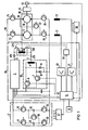
- FIG. 1 shows an arrangement for controlling an inductive load 1, in the present case for speed control of a direct current drive for an electric vehicle, in which two armatures 17, 18 are arranged on a common shaft 20 working on a drive wheel 19. With 21, 22 excitation windings of the DC motor are designated.
- the armatures 17, 18 are fed via semiconductor switches 23 to 27 and an armature and excitation current barker 28 from batteries 29, 30 divided into groups, to which semiconductor switches 31 to 35 are assigned.
- the batteries 29, 30 and / or the armatures 17, 18 are turned on by means of a speed setpoint generator 15 by the switches 23 to 27 controlled by a control unit 14 via the switching device 56 or switches 31 to 35 by the switching device 57 Semen switched to parallel connection and vice versa.
- the armature and excitation current controller 28 for the drive 16 contains a semiconductor controller 2, which - as shown in FIG. 2 - is formed from a parallel connection of at least two controllable semiconductor valves 6, 7 (transistors) connected to a suction transformer 4 with center tap 5.
- the direct current motor 1 is connected via the semiconductor actuator 2 to a direct current source 3, which is connected to a Süitz capacitor 13 in parallel.
- the connection point 8 of the semiconductor valves 6, 7 of the same forward direction is with a + pole of the direct voltage source 3 and the center tap 5 of the suction transformer 4 with one pole of the inductive one Load 1 connected.
- the connection point 9 of the semiconductor valve 6 with the suction transformer 4 is connected to the minus pole via a freewheeling diode 11.
- the connection point 10 of the semiconductor valve 7 is connected to the suction transformer 4 via a free-wheeling diode 12 with the minus pole.
- the two semiconductor valves 6, 7 are opened and closed at 180 ° to each other at the clock frequency. 14 serves this purpose the control unit, which is controllable by a set value transmitter 15 and two generated 180 0 electrically offset clock signals via actuators 54, 55, the two semiconductor valves 6, control. 7
- the semiconductor valves 6, 7 are operated with a modulation factor a equal to 0.5.
- the voltages shown in FIG. 3 then result at the points denoted by A to D.
- the semiconductor valve 6 is opened by a clock frequency signal with a pulse-psuse ratio of 0.5.
- the input voltage is thus present at point A over the predetermined period of time.
- this switch-on time in which the half-light valve 7 is closed, a current flow in the inductive load 1 is maintained via the freewheeling diode 12 and via the part B, C of the suction transformer 4.
- the semiconductor valve 6 is closed and the semiconductor valve 7 is opened by a clock frequency signal passed via the actuator 55.
- the current flow in the inductive load 1 is maintained via the freewheeling diode 11 and the parts A, C of the suction transistor 4.
- the input voltage is present at point B. of the suction transformer 4.
- the suction transformer acts as a symmetrical voltage divider for the input voltage present at point B, so that half the voltage 1 / 2U E2 of the DC voltage source is present at point C due to the fact that the semiconductor valves 6, 7 with a degree of deflection of 0, 5 alternately opened and closed against each other by 180 °, there is a continuous DC voltage at the consumer, which results from the temporal addition of the voltage blocks 1 / 2U E1 + 1 / 2U E2
- a further hat-lead controller 36 is connected in parallel to the semiconductor actuator 2, which is constructed in the same way as the semiconductor actuator 2.
- the center tap of the suction transformers 4 of the two semiconductor bellers 2 and 36 is connected to the ends of a third suction transformer 37 with center tap 38, whereby the center tap 38 of the third suction transformer 37 is connected to the + pole of the busbar 39.
- Both semiconductor actuators 2, 36 are driven by clock frequency signals generated by the control unit 14 with the same modulation ratio a, but offset by 90 °, so that they are fed to the third suction transformer Output voltages are offset from one another by 180 °.
- the excitation windings 21, 22 can also be controlled by the control device, each via an excitation current semiconductor actuator 40, 41 known per se.
- the semiconductor valves 6, 7 are operated in stages with a constant modulation degree a of at least approximately only 0.25, 0.5, 0.75 or 1 in order to generate a continuous DC voltage at the armatures. As shown in principle in FIG. 3 for FIG. 2, this results in a seamless DC voltage at armatures 17, 18 with a height of 25, 50, 75 or 100% of the applied battery voltage.
- the degree of modulation of the excitation current controllers 40, 41 can be changed for speed control in the intermediate ranges. It is advantageous to equip the control unit 14 with a computer to which the voltage of a tachometer machine 52 is supplied as the actual value. For a corresponding setpoint specification, the computer determines which modulation level 0.25, 0.5, 0.75 or 1 must be specified for reaching the current ripple minimum and then controls the excitation current controllers 40, 41 so that the specified speed is reached.
- the suction transformer 4 is expediently arranged in a bridge circuit of semiconductor valves 6, 7, 49, 53, which is known per se, with a free-wheeling diode 11 or 12 or 54 or 55 being connected in parallel to each semiconductor valve, as shown in FIG. 4
- a switching device 50 (FIG. 1) is expediently provided, which in the event of shading or failure of an actuator, e.g. of the actuator 36 automatically switches the drive 16 to the still existing steep 2, whereby a switch 47a is closed and the steep 36 is switched off by opening the second switch 47b.
- the drive motor can be operated solely via the actuator 2.
- This case is shown in principle in Fig. 2.
- the clock frequency at the inductive load 1 is doubled and the current vibration width is increased to a quarter compared to the circuit arrangements according to FIG. 1. If clock frequency signals for a constant modulation level of the semiconductor valves of at least approximately 0.5 or 1 are generated in the control device, the result is that a DC voltage without ripple is present at the DC motor. Noise excitations from the put frequency can therefore no longer occur.
- Fig. 5 shows a further parallel arrangement of steep and suction transformers to further reduce the current vibration range and increase the number of minima of the current ripple.
- a further parallel connection of two semiconductor actuators 42, 43 with suction transformers 37, 44 is provided, and the center taps 38, 45 of the suction transformers 37, 44 are connected to a further suction transformer 56, whose center tap 57 is connected to a pole plus of the inductive load 1.
- Curve III for an arrangement with two actuators (three suction transformers) according to FIG. 1,
- Curve IV for an arrangement with four steep slopes (seven suction transforms) according to FIG. 5.
- the low-induction suction transformer with a closed cutting core arranged in a circuit according to FIG. 2 has, for example, an inductance of approximately .mu.H.
Landscapes
- Engineering & Computer Science (AREA)
- Power Engineering (AREA)
- Dc-Dc Converters (AREA)
- Control Of Direct Current Motors (AREA)
Applications Claiming Priority (2)
| Application Number | Priority Date | Filing Date | Title |
|---|---|---|---|
| DE3433886 | 1984-09-14 | ||
| DE19843433886 DE3433886A1 (de) | 1984-09-14 | 1984-09-14 | Steuereinrichtung fuer einen gleichstrom-halbleitersteller |
Publications (2)
| Publication Number | Publication Date |
|---|---|
| EP0178446A1 true EP0178446A1 (fr) | 1986-04-23 |
| EP0178446B1 EP0178446B1 (fr) | 1989-01-25 |
Family
ID=6245461
Family Applications (1)
| Application Number | Title | Priority Date | Filing Date |
|---|---|---|---|
| EP85111298A Expired EP0178446B1 (fr) | 1984-09-14 | 1985-09-06 | Dispositif de hacheur à semi-conducteur |
Country Status (8)
| Country | Link |
|---|---|
| US (1) | US4634943A (fr) |
| EP (1) | EP0178446B1 (fr) |
| KR (1) | KR930000416B1 (fr) |
| AU (1) | AU563677B2 (fr) |
| CA (1) | CA1240362A (fr) |
| DE (2) | DE3433886A1 (fr) |
| DK (1) | DK409085A (fr) |
| TR (1) | TR22510A (fr) |
Cited By (3)
| Publication number | Priority date | Publication date | Assignee | Title |
|---|---|---|---|---|
| EP0470499A3 (en) * | 1990-08-07 | 1992-05-06 | Performance Controls, Inc. | Pulse-width modulated circuit for driving a load |
| DE102012201269A1 (de) | 2012-01-30 | 2013-08-01 | Siemens Aktiengesellschaft | Wahlweise Steuerung eines Wechselstrommotors oder Gleichstrommotors |
| DE102017217948A1 (de) | 2017-10-09 | 2019-04-11 | Siemens Aktiengesellschaft | Antriebseinrichtung bzw. deren Betrieb |
Families Citing this family (17)
| Publication number | Priority date | Publication date | Assignee | Title |
|---|---|---|---|---|
| US4814685A (en) * | 1987-12-04 | 1989-03-21 | Pacesetter Infusion, Ltd. | Inductive power converter for use with variable input and output voltages |
| US5070292A (en) * | 1989-11-13 | 1991-12-03 | Performance Controls, Inc. | Pulse-width modulated circuit for driving a load |
| US4984148A (en) * | 1990-05-29 | 1991-01-08 | Westinghouse Electric Corp. | Two-phase bang-bang current control synchronizer |
| DE9109274U1 (de) * | 1991-07-26 | 1991-09-19 | Siemens AG, 8000 München | Tiefsetzsteller |
| US5493201A (en) * | 1994-11-15 | 1996-02-20 | Sundstrand Corporation | Starter/generator system and method utilizing a low voltage source |
| US6694438B1 (en) * | 1999-07-02 | 2004-02-17 | Advanced Energy Industries, Inc. | System for controlling the delivery of power to DC computer components |
| US6545450B1 (en) * | 1999-07-02 | 2003-04-08 | Advanced Energy Industries, Inc. | Multiple power converter system using combining transformers |
| DE10013672A1 (de) * | 2000-03-20 | 2001-10-18 | Siemens Ag | Stromrichterschaltung |
| US20040233690A1 (en) * | 2001-08-17 | 2004-11-25 | Ledenev Anatoli V. | Multiple power converter system using combining transformers |
| EP1808952B1 (fr) * | 2003-08-21 | 2014-04-16 | Marvell World Trade Ltd. | Régulateur de tension |
| US7760525B2 (en) * | 2003-08-21 | 2010-07-20 | Marvell World Trade Ltd. | Voltage regulator |
| US7990117B2 (en) * | 2007-07-06 | 2011-08-02 | Northem Power Systems, Inc. | Low-loss control of DC-DC converters in an energy storage system |
| CA2737134C (fr) | 2007-10-15 | 2017-10-10 | Ampt, Llc | Systemes pour energie solaire hautement efficace |
| US9442504B2 (en) | 2009-04-17 | 2016-09-13 | Ampt, Llc | Methods and apparatus for adaptive operation of solar power systems |
| WO2011049985A1 (fr) | 2009-10-19 | 2011-04-28 | Ampt, Llc | Topologie novatrice de convertisseur de chaîne de panneau solaire |
| US9397497B2 (en) | 2013-03-15 | 2016-07-19 | Ampt, Llc | High efficiency interleaved solar power supply system |
| CN105229914B (zh) * | 2013-03-15 | 2019-04-19 | Ampt有限公司 | 高效输送太阳能电力的方法和高效太阳能电力系统 |
Citations (3)
| Publication number | Priority date | Publication date | Assignee | Title |
|---|---|---|---|---|
| FR1299040A (fr) * | 1961-06-07 | 1962-07-20 | Constr Telephoniques | Convertisseur de tension continue |
| GB1371418A (en) * | 1972-09-15 | 1974-10-23 | Pioneer Magnetics Inc | Current sharing parallel transistor circuit |
| US4417197A (en) * | 1981-07-27 | 1983-11-22 | Schwarz Francisc C | Electronic system for simultaneous control of two or more pulse modulators |
Family Cites Families (1)
| Publication number | Priority date | Publication date | Assignee | Title |
|---|---|---|---|---|
| DE2655077C3 (de) * | 1976-12-04 | 1987-10-22 | Indramat Gesellschaft für Industrie-Rationalisierung und Automatisierung mbH, 8770 Lohr | Impulsbreitenmodulierter Vier- Quadranten-Gleichstromsteller |
-
1984
- 1984-09-14 DE DE19843433886 patent/DE3433886A1/de not_active Withdrawn
-
1985
- 1985-09-06 DE DE8585111298T patent/DE3567995D1/de not_active Expired
- 1985-09-06 EP EP85111298A patent/EP0178446B1/fr not_active Expired
- 1985-09-09 DK DK409085A patent/DK409085A/da not_active Application Discontinuation
- 1985-09-12 CA CA000490556A patent/CA1240362A/fr not_active Expired
- 1985-09-12 TR TR37849A patent/TR22510A/xx unknown
- 1985-09-12 US US06/775,473 patent/US4634943A/en not_active Expired - Fee Related
- 1985-09-13 AU AU47438/85A patent/AU563677B2/en not_active Ceased
- 1985-09-13 KR KR1019850006690A patent/KR930000416B1/ko not_active Expired - Fee Related
Patent Citations (3)
| Publication number | Priority date | Publication date | Assignee | Title |
|---|---|---|---|---|
| FR1299040A (fr) * | 1961-06-07 | 1962-07-20 | Constr Telephoniques | Convertisseur de tension continue |
| GB1371418A (en) * | 1972-09-15 | 1974-10-23 | Pioneer Magnetics Inc | Current sharing parallel transistor circuit |
| US4417197A (en) * | 1981-07-27 | 1983-11-22 | Schwarz Francisc C | Electronic system for simultaneous control of two or more pulse modulators |
Non-Patent Citations (1)
| Title |
|---|
| IEEE TRANSACTIONS ON INDUSTRY APPLICATIONS, Band IA-17, Nr. 6, 1981, Seiten 626-631, New York, US; B.K. BOSE "A microprocessor-based control system for a near-term electric vehicle" * |
Cited By (4)
| Publication number | Priority date | Publication date | Assignee | Title |
|---|---|---|---|---|
| EP0470499A3 (en) * | 1990-08-07 | 1992-05-06 | Performance Controls, Inc. | Pulse-width modulated circuit for driving a load |
| DE102012201269A1 (de) | 2012-01-30 | 2013-08-01 | Siemens Aktiengesellschaft | Wahlweise Steuerung eines Wechselstrommotors oder Gleichstrommotors |
| WO2013113540A2 (fr) | 2012-01-30 | 2013-08-08 | Siemens Aktiengesellschaft | Commande sélective d'un moteur à courant alternatif ou d'un moteur à courant continu |
| DE102017217948A1 (de) | 2017-10-09 | 2019-04-11 | Siemens Aktiengesellschaft | Antriebseinrichtung bzw. deren Betrieb |
Also Published As
| Publication number | Publication date |
|---|---|
| DE3567995D1 (en) | 1989-03-02 |
| AU563677B2 (en) | 1987-07-16 |
| DK409085D0 (da) | 1985-09-09 |
| KR860002895A (ko) | 1986-04-30 |
| KR930000416B1 (ko) | 1993-01-18 |
| EP0178446B1 (fr) | 1989-01-25 |
| AU4743885A (en) | 1986-03-20 |
| TR22510A (tr) | 1987-09-16 |
| US4634943A (en) | 1987-01-06 |
| DE3433886A1 (de) | 1986-03-27 |
| CA1240362A (fr) | 1988-08-09 |
| DK409085A (da) | 1986-03-15 |
Similar Documents
| Publication | Publication Date | Title |
|---|---|---|
| EP0178446A1 (fr) | Dispositif de hacheur à semi-conducteur | |
| EP1157320B1 (fr) | Procede permettant de generer une tension continue regulee a partir d'une tension alternative, et dispositif d'alimentation en courant pour la mise en oeuvre de ce procede | |
| EP0685940B1 (fr) | Convertisseur modulé par la largeur d'impulsion pour le fonctionnement de consommateurs d'électricité | |
| DE3101102C2 (fr) | ||
| DE3914863A1 (de) | Steuersystem fuer einen kraftfahrzeugladegenerator | |
| DE3530966C2 (fr) | ||
| DE69310780T2 (de) | Wechselrichter für Elektrofahrzeug | |
| EP0098460B1 (fr) | Dispositif de régulation pour organe électrique de manoeuvre | |
| DE3238127A1 (de) | Anordnung zur steuerung von halbleiterschaltungen | |
| DE19711768B4 (de) | Elektromagnetischer Stellantrieb | |
| DE2525322A1 (de) | Wechselspannungs-regler | |
| EP0243948B1 (fr) | Circuit de contrôle pour une lampe à arc | |
| DE19540512A1 (de) | Schaltungsanordnung zur Erzeugung von betragsmäßig unterschiedlichen Gleichspannungen | |
| DE2112580C3 (de) | Aus einer Wechselspannungsquelle gespeiste Stromrichterschaltung zur Drehzahlsteuerung eines Gleichstrommotors | |
| DE3545770C2 (fr) | ||
| DE2853619A1 (de) | Gleichrichteranordnung | |
| EP0613236B1 (fr) | Dispositif de mise en service d'un compresseur pour climatiseurs d'armoires électriques | |
| DE3600170A1 (de) | Induktionsheizgeraet | |
| EP0491690B1 (fr) | Procede de reglage par impulsion pour un onduleur a plusieurs etages | |
| DE3100960A1 (de) | Elektrische leistungsversorgungsvorrichtung | |
| EP4560911A1 (fr) | Procédé de commande à fréquence variable pour actionneur de frein modulaire | |
| DE2114690A1 (de) | Magnetischer Stellantrieb | |
| EP4560910A1 (fr) | Structure et procédé de commande pour un actionneur de frein modulaire comprenant au moins deux branches de l'actionneur de frein | |
| EP4329180A1 (fr) | Procédé de commande pour un actionneur de frein modulaire | |
| DE102005047787B4 (de) | Ansteuerschaltung und Ansteuergerät |
Legal Events
| Date | Code | Title | Description |
|---|---|---|---|
| PUAI | Public reference made under article 153(3) epc to a published international application that has entered the european phase |
Free format text: ORIGINAL CODE: 0009012 |
|
| AK | Designated contracting states |
Kind code of ref document: A1 Designated state(s): DE FR GB IT NL SE |
|
| 17P | Request for examination filed |
Effective date: 19860527 |
|
| 17Q | First examination report despatched |
Effective date: 19871130 |
|
| GRAA | (expected) grant |
Free format text: ORIGINAL CODE: 0009210 |
|
| AK | Designated contracting states |
Kind code of ref document: B1 Designated state(s): DE FR GB IT NL SE |
|
| REF | Corresponds to: |
Ref document number: 3567995 Country of ref document: DE Date of ref document: 19890302 |
|
| ET | Fr: translation filed | ||
| ITF | It: translation for a ep patent filed | ||
| GBT | Gb: translation of ep patent filed (gb section 77(6)(a)/1977) | ||
| PLBE | No opposition filed within time limit |
Free format text: ORIGINAL CODE: 0009261 |
|
| STAA | Information on the status of an ep patent application or granted ep patent |
Free format text: STATUS: NO OPPOSITION FILED WITHIN TIME LIMIT |
|
| 26N | No opposition filed | ||
| ITTA | It: last paid annual fee | ||
| EAL | Se: european patent in force in sweden |
Ref document number: 85111298.7 |
|
| PGFP | Annual fee paid to national office [announced via postgrant information from national office to epo] |
Ref country code: GB Payment date: 19980817 Year of fee payment: 14 |
|
| PGFP | Annual fee paid to national office [announced via postgrant information from national office to epo] |
Ref country code: SE Payment date: 19980909 Year of fee payment: 14 |
|
| PGFP | Annual fee paid to national office [announced via postgrant information from national office to epo] |
Ref country code: FR Payment date: 19980916 Year of fee payment: 14 |
|
| PGFP | Annual fee paid to national office [announced via postgrant information from national office to epo] |
Ref country code: NL Payment date: 19980921 Year of fee payment: 14 |
|
| PGFP | Annual fee paid to national office [announced via postgrant information from national office to epo] |
Ref country code: DE Payment date: 19981117 Year of fee payment: 14 |
|
| PG25 | Lapsed in a contracting state [announced via postgrant information from national office to epo] |
Ref country code: GB Free format text: LAPSE BECAUSE OF NON-PAYMENT OF DUE FEES Effective date: 19990906 |
|
| PG25 | Lapsed in a contracting state [announced via postgrant information from national office to epo] |
Ref country code: SE Free format text: THE PATENT HAS BEEN ANNULLED BY A DECISION OF A NATIONAL AUTHORITY Effective date: 19990929 |
|
| PG25 | Lapsed in a contracting state [announced via postgrant information from national office to epo] |
Ref country code: NL Free format text: LAPSE BECAUSE OF NON-PAYMENT OF DUE FEES Effective date: 20000401 |
|
| GBPC | Gb: european patent ceased through non-payment of renewal fee |
Effective date: 19990906 |
|
| EUG | Se: european patent has lapsed |
Ref document number: 85111298.7 |
|
| PG25 | Lapsed in a contracting state [announced via postgrant information from national office to epo] |
Ref country code: FR Free format text: LAPSE BECAUSE OF NON-PAYMENT OF DUE FEES Effective date: 20000531 |
|
| NLV4 | Nl: lapsed or anulled due to non-payment of the annual fee |
Effective date: 20000401 |
|
| PG25 | Lapsed in a contracting state [announced via postgrant information from national office to epo] |
Ref country code: DE Free format text: LAPSE BECAUSE OF NON-PAYMENT OF DUE FEES Effective date: 20000701 |
|
| REG | Reference to a national code |
Ref country code: FR Ref legal event code: ST |