EP0181235B1 - Cryosystem for biological material - Google Patents
Cryosystem for biological material Download PDFInfo
- Publication number
- EP0181235B1 EP0181235B1 EP85308159A EP85308159A EP0181235B1 EP 0181235 B1 EP0181235 B1 EP 0181235B1 EP 85308159 A EP85308159 A EP 85308159A EP 85308159 A EP85308159 A EP 85308159A EP 0181235 B1 EP0181235 B1 EP 0181235B1
- Authority
- EP
- European Patent Office
- Prior art keywords
- cryo
- core member
- cell assembly
- temperature
- assembly according
- Prior art date
- Legal status (The legal status is an assumption and is not a legal conclusion. Google has not performed a legal analysis and makes no representation as to the accuracy of the status listed.)
- Expired
Links
- 239000012620 biological material Substances 0.000 title claims description 16
- 239000010902 straw Substances 0.000 claims description 30
- 238000007710 freezing Methods 0.000 claims description 20
- 230000008014 freezing Effects 0.000 claims description 20
- 239000004411 aluminium Substances 0.000 claims description 12
- XAGFODPZIPBFFR-UHFFFAOYSA-N aluminium Chemical compound [Al] XAGFODPZIPBFFR-UHFFFAOYSA-N 0.000 claims description 12
- 229910052782 aluminium Inorganic materials 0.000 claims description 12
- 238000010257 thawing Methods 0.000 claims description 10
- 238000006243 chemical reaction Methods 0.000 claims 1
- 238000012545 processing Methods 0.000 description 14
- 239000000463 material Substances 0.000 description 13
- IJGRMHOSHXDMSA-UHFFFAOYSA-N Atomic nitrogen Chemical compound N#N IJGRMHOSHXDMSA-UHFFFAOYSA-N 0.000 description 8
- 239000007787 solid Substances 0.000 description 8
- 239000011810 insulating material Substances 0.000 description 7
- 239000007788 liquid Substances 0.000 description 7
- 238000010586 diagram Methods 0.000 description 6
- 210000004027 cell Anatomy 0.000 description 5
- 239000013078 crystal Substances 0.000 description 5
- BASFCYQUMIYNBI-UHFFFAOYSA-N platinum Chemical compound [Pt] BASFCYQUMIYNBI-UHFFFAOYSA-N 0.000 description 5
- 238000004804 winding Methods 0.000 description 5
- RYGMFSIKBFXOCR-UHFFFAOYSA-N Copper Chemical compound [Cu] RYGMFSIKBFXOCR-UHFFFAOYSA-N 0.000 description 4
- 239000003990 capacitor Substances 0.000 description 4
- 239000002826 coolant Substances 0.000 description 4
- 229910052802 copper Inorganic materials 0.000 description 4
- 239000010949 copper Substances 0.000 description 4
- 229910052757 nitrogen Inorganic materials 0.000 description 4
- 239000000523 sample Substances 0.000 description 4
- 229910001220 stainless steel Inorganic materials 0.000 description 4
- 239000010935 stainless steel Substances 0.000 description 4
- 238000003860 storage Methods 0.000 description 4
- 230000007306 turnover Effects 0.000 description 4
- 238000001816 cooling Methods 0.000 description 3
- 238000010438 heat treatment Methods 0.000 description 3
- 230000000670 limiting effect Effects 0.000 description 3
- 210000000582 semen Anatomy 0.000 description 3
- 210000001519 tissue Anatomy 0.000 description 3
- XUIMIQQOPSSXEZ-UHFFFAOYSA-N Silicon Chemical compound [Si] XUIMIQQOPSSXEZ-UHFFFAOYSA-N 0.000 description 2
- 230000015572 biosynthetic process Effects 0.000 description 2
- 238000010276 construction Methods 0.000 description 2
- 238000011109 contamination Methods 0.000 description 2
- 230000007423 decrease Effects 0.000 description 2
- 238000001125 extrusion Methods 0.000 description 2
- 230000005669 field effect Effects 0.000 description 2
- 239000006260 foam Substances 0.000 description 2
- 230000006870 function Effects 0.000 description 2
- 238000003754 machining Methods 0.000 description 2
- 230000005426 magnetic field effect Effects 0.000 description 2
- 238000000034 method Methods 0.000 description 2
- 230000000149 penetrating effect Effects 0.000 description 2
- 230000035515 penetration Effects 0.000 description 2
- 239000004033 plastic Substances 0.000 description 2
- 229920003023 plastic Polymers 0.000 description 2
- 238000002360 preparation method Methods 0.000 description 2
- 230000000630 rising effect Effects 0.000 description 2
- 230000035945 sensitivity Effects 0.000 description 2
- 229910052710 silicon Inorganic materials 0.000 description 2
- 239000010703 silicon Substances 0.000 description 2
- 230000001960 triggered effect Effects 0.000 description 2
- 230000000007 visual effect Effects 0.000 description 2
- BQCADISMDOOEFD-UHFFFAOYSA-N Silver Chemical compound [Ag] BQCADISMDOOEFD-UHFFFAOYSA-N 0.000 description 1
- 238000007792 addition Methods 0.000 description 1
- 230000004075 alteration Effects 0.000 description 1
- 239000003708 ampul Substances 0.000 description 1
- 230000002528 anti-freeze Effects 0.000 description 1
- 230000000903 blocking effect Effects 0.000 description 1
- 239000008280 blood Substances 0.000 description 1
- 210000004369 blood Anatomy 0.000 description 1
- 230000015556 catabolic process Effects 0.000 description 1
- 210000003855 cell nucleus Anatomy 0.000 description 1
- 230000008859 change Effects 0.000 description 1
- 239000002800 charge carrier Substances 0.000 description 1
- 239000000356 contaminant Substances 0.000 description 1
- 238000005138 cryopreservation Methods 0.000 description 1
- 230000003247 decreasing effect Effects 0.000 description 1
- 238000013461 design Methods 0.000 description 1
- 230000000694 effects Effects 0.000 description 1
- 210000002257 embryonic structure Anatomy 0.000 description 1
- 238000000605 extraction Methods 0.000 description 1
- -1 felt Substances 0.000 description 1
- 239000012530 fluid Substances 0.000 description 1
- 230000000762 glandular Effects 0.000 description 1
- 239000011521 glass Substances 0.000 description 1
- 230000017525 heat dissipation Effects 0.000 description 1
- 238000002347 injection Methods 0.000 description 1
- 239000007924 injection Substances 0.000 description 1
- 238000003780 insertion Methods 0.000 description 1
- 230000037431 insertion Effects 0.000 description 1
- 210000004185 liver Anatomy 0.000 description 1
- 210000001161 mammalian embryo Anatomy 0.000 description 1
- 239000012528 membrane Substances 0.000 description 1
- 238000012986 modification Methods 0.000 description 1
- 230000004048 modification Effects 0.000 description 1
- 238000012806 monitoring device Methods 0.000 description 1
- 229910001120 nichrome Inorganic materials 0.000 description 1
- 238000003825 pressing Methods 0.000 description 1
- 108090000623 proteins and genes Proteins 0.000 description 1
- 238000011084 recovery Methods 0.000 description 1
- 230000002829 reductive effect Effects 0.000 description 1
- 230000004044 response Effects 0.000 description 1
- 230000000717 retained effect Effects 0.000 description 1
- 238000007789 sealing Methods 0.000 description 1
- 230000035939 shock Effects 0.000 description 1
- 229910052709 silver Inorganic materials 0.000 description 1
- 239000004332 silver Substances 0.000 description 1
- 229910000679 solder Inorganic materials 0.000 description 1
- 210000000952 spleen Anatomy 0.000 description 1
- 230000036962 time dependent Effects 0.000 description 1
- 238000012546 transfer Methods 0.000 description 1
- 238000010792 warming Methods 0.000 description 1
- XLYOFNOQVPJJNP-UHFFFAOYSA-N water Substances O XLYOFNOQVPJJNP-UHFFFAOYSA-N 0.000 description 1
- 239000002023 wood Substances 0.000 description 1
Images




Classifications
-
- A—HUMAN NECESSITIES
- A01—AGRICULTURE; FORESTRY; ANIMAL HUSBANDRY; HUNTING; TRAPPING; FISHING
- A01N—PRESERVATION OF BODIES OF HUMANS OR ANIMALS OR PLANTS OR PARTS THEREOF; BIOCIDES, e.g. AS DISINFECTANTS, AS PESTICIDES OR AS HERBICIDES; PEST REPELLANTS OR ATTRACTANTS; PLANT GROWTH REGULATORS
- A01N1/00—Preservation of bodies of humans or animals, or parts thereof
- A01N1/10—Preservation of living parts
- A01N1/14—Mechanical aspects of preservation; Apparatus or containers therefor
- A01N1/142—Apparatus
-
- A—HUMAN NECESSITIES
- A01—AGRICULTURE; FORESTRY; ANIMAL HUSBANDRY; HUNTING; TRAPPING; FISHING
- A01N—PRESERVATION OF BODIES OF HUMANS OR ANIMALS OR PLANTS OR PARTS THEREOF; BIOCIDES, e.g. AS DISINFECTANTS, AS PESTICIDES OR AS HERBICIDES; PEST REPELLANTS OR ATTRACTANTS; PLANT GROWTH REGULATORS
- A01N1/00—Preservation of bodies of humans or animals, or parts thereof
- A01N1/10—Preservation of living parts
-
- F—MECHANICAL ENGINEERING; LIGHTING; HEATING; WEAPONS; BLASTING
- F25—REFRIGERATION OR COOLING; COMBINED HEATING AND REFRIGERATION SYSTEMS; HEAT PUMP SYSTEMS; MANUFACTURE OR STORAGE OF ICE; LIQUEFACTION SOLIDIFICATION OF GASES
- F25D—REFRIGERATORS; COLD ROOMS; ICE-BOXES; COOLING OR FREEZING APPARATUS NOT OTHERWISE PROVIDED FOR
- F25D25/00—Charging, supporting, and discharging the articles to be cooled
- F25D25/005—Charging, supporting, and discharging the articles to be cooled using containers
-
- F—MECHANICAL ENGINEERING; LIGHTING; HEATING; WEAPONS; BLASTING
- F25—REFRIGERATION OR COOLING; COMBINED HEATING AND REFRIGERATION SYSTEMS; HEAT PUMP SYSTEMS; MANUFACTURE OR STORAGE OF ICE; LIQUEFACTION SOLIDIFICATION OF GASES
- F25D—REFRIGERATORS; COLD ROOMS; ICE-BOXES; COOLING OR FREEZING APPARATUS NOT OTHERWISE PROVIDED FOR
- F25D3/00—Devices using other cold materials; Devices using cold-storage bodies
- F25D3/10—Devices using other cold materials; Devices using cold-storage bodies using liquefied gases, e.g. liquid air
-
- G—PHYSICS
- G01—MEASURING; TESTING
- G01N—INVESTIGATING OR ANALYSING MATERIALS BY DETERMINING THEIR CHEMICAL OR PHYSICAL PROPERTIES
- G01N1/00—Sampling; Preparing specimens for investigation
- G01N1/28—Preparing specimens for investigation including physical details of (bio-)chemical methods covered elsewhere, e.g. G01N33/50, C12Q
- G01N1/42—Low-temperature sample treatment, e.g. cryofixation
Definitions
- the present invention relates to the field of cryo-preservation.
- the present invention relates to a system suitable for deep freezing and thawing living biological material.
- Samples of materials such as semen are typically frozen in straws (approximately 2mm diameter and 130mm length) so that each sperm cell is in close proximity to the walls of the straw through which cooling is performed.
- Embryos are sometimes dehydrated at low temperatures and this requires constant temperature of -6°C for approximately 30 minutes.
- Other tissues such as liver, spleen, glandular material, blood fractions and botanical "gene bank” material all have specific freezing requirements.
- a further disadvantage of certain prior art machines concerns their reliability. Apparatus which utilizes moving parts such as mechanical valves for injecting liquid nitrogen (LN2) etc may be prone to breakdown. Moreover such apparatus consumes relatively large quantities of LN2, eg 10-15 litres per cycle. Freezing apparatus is known (from E-A 117037) in which there are at least two different heat transfer components and in which the tubes 1 are cooled differentially. This apparatus has the disadvantage that the isotherms in the apparatus do not lie substantially along concentric cylindrical surfaces and that as a result of this heat flow from the tubes is not uniformly radial.
- the apparatus of the present invention is based on the thermal bridge principle, ie. the apparatus operates by locating a heat source and a heat sink in heat conducting relationship with the biological material to be processed.
- the apparatus of the present invention includes a cryo-cell assembly.
- the cryo-cell assembly may include a space for receiving biological material to be processed.
- the cryo-cell assembly preferably includes a source of heat positioned in heat conducting relationship with said space.
- the cryo-cell assembly of the present invention may be provided in any convenient form.
- the cryo-cell assembly preferably is adapted to generate substantially concentric isotherms within the space for receiving biological material.
- the cryo-cell assembly preferably comprises a plurality of nested members.
- the assembly may include an innermost or core member, a thermally insulating layer and an outer member surrounding the insulating layer.
- the innermost or core member may be arranged in heat conducting relationship with the space for receiving biological material.
- the core member preferably comprises a tubular member.
- the core member may include one or more slots formed, about the perimeter of the core member. The slots preferably extend longitudinally along the core member. The slots may be formed in the inner or outer wall surface of the core member.
- the inner core member may be formed of any suitable material.
- the inner core member may be formed of a material having good thermal conductivity such as copper, aluminium or silver. Good grade aluminium (ie. one having high purity) is preferable.
- the inner core member may be formed in any suitable manner eg. by extrusion or machining.
- the slots may be formed with the core member or they may be machined therein after forming.
- the slots are substantially evenly spaced around the perimeter of the core member.
- the or each slot may be adapted to accept 2mm diameter specimen straw.
- the slots may be milled on the internal wall of the core member.
- the slots may be milled to a depth and width of approximately 3mm.
- One slot may be formed slightly larger than the others for accepting a temperature sensor.
- the assembly may include an intermediate member surrounding the core member.
- the intermediate member preferably comprises a tubular member.
- the intermediate member may be arranged in heat conducting relationship with the core member.
- the intermediate member preferably is slidably fitted over the inner core member.
- the inner core member may be slidable relative to the intermediate member to facilitate removal and placement of samples.
- a suitable base member may be attached to one (the lower) end of the inner core member or to the intermediate member.
- the base member may be adapted to support specimen straws and/or to prevent liquids or other materials penetrating into the insulating layer of the assembly.
- the supporting base preferably comprises a flat plate.
- the plate may be approximately circular and of a diameter similar to the internal diameter of the intermediate member.
- a suitable handle may be attached to the core member to facilitate its removal from the assembly.
- the handle may comprise eg. a wire frame bent to an inverted U shape and held to the core member.
- the handle and supporting base member preferably comprise stainless steel.
- the intermediate member may be dispensed with.
- Specimen straws may be placed into and removed from the assembly without moving the inner core member.
- a suitable support frame may be provided for supporting specimen straws.
- the support frame may be adapted to slide into the core member.
- the support frame may include a handle to facilitate manipulation of specimen straws.
- the support frame may comprise an elongate member having a plurality of support elements at one end thereof.
- the support elements may extend radially from the elongate member and substantially perpendicular to the elongate member.
- Each support element may be adapted to engage and support the lower end of a specimen straw.
- the cryo-cell assembly includes heat generating means.
- the heat generating means may be adapted to surround the intermediate member and/or the inner core member.
- the heat generating means preferably includes a heater element adapted to surround the intermediate member and/or the inner core member.
- the heat generating means comprises a heater element wound around the external wall of the intermediate member. Where specimen receiving slots are formed on the internal wall of the core member the heater element may be wound directly onto the external surface of the core member.
- the heater element preferably comprises resistance wire such as nichrome wire.
- the resistance wire element may be wound around the intermediate member with uniform spacing between the windings.
- the heater element preferably comprises a pair of windings having parallel windings evenly spaced with current passing in opposite directions to minimize magnetic field effects in the vicinity of the heater element and specimen.
- the intermediate member may include a pair of helical grooves cut into its external wall surface for retaining the heater element.
- the helical grooves may be substantially uniformally distributed over the length of the intermediate member.
- the helical grooves may comprise a pair of parallel threads having a pitch of 2 per cm each and a depth of 0.5 mm.
- the resistance wire may be wound into one of the grooves and returned along the other groove to minimize the previously noted magnetic field effects.
- the resistance of the heating element may be approximately 30 ohms.
- the thermally insulating layer may be adapted to surround the heater element.
- the insulating layer may be provided in any suitable manner.
- the insulating layer may comprise wood, felt, foam or other suitable material.
- the insulating layer may be formed in any suitable form.
- the insulating layer may comprise a sleeve of selected grade insulating material.
- the grade of insulating material may be selected to provide the optimum flow rate of heat between the core member and outer member. In one form the insulating material may be selected to have a heat conduction of 1mW/cm°C.
- the insulating layer may be wound evenly around the intermediate member or be pre-formed and fitted over the intermediate member. Alternatively the insulating layer may be injection molded into the cavity between the intermediate member and the outer member of the cryo-cell assembly.
- the intermediate member and insulating layer may be firmly fitted into the outer member. After fitment, the gap formed between the top edges of the intermediate and outer members (annular where the assembly is cylindrical) preferably is sealed to minimize penetration of moisture into the insulating layer. A pair of connecting leads for carrying current to the heater windings may be passed through the seal.
- the outer member which may comprise the housing of the cryo-cell assembly preferably comprises a tubular member surrounding the insulating layer.
- the outer member preferably includes a base.
- the base may comprise a plate or a cap member fitted at one end of the outer member.
- the plate preferably is welded or soldered across the opening with suitable solder material.
- the cap preferably is retained in the end of the outer member by means of an interference fit, eg. the cap may be pressure fitted or crimped onto the end of the outer member.
- the outer member or housing preferably comprises a material having good thermal conductivity. Copper or high purity aluminium is preferable for this purpose.
- the outer member or housing may be formed in any convenient manner eg. by extrusion or machining.
- the nested members of the cryo-cell assembly may comprise substantially cylindrical tubular members.
- the tubular members preferably are concentric.
- the arrangement preferably is such that heat flow is uniformly radial and layers are cylindrical isotherms.
- all specimen and the temperature sensors may have the same temperature both around the core member and along it.
- the cryo-cell assembly of the present invention may be formed with any suitable dimensions.
- the cryo-cell assembly of the present invention is of the order of several centimeters in diameter (4-5cm) and of the order of 15 cm in height.
- a closure may be provided for closing the top of the cryo-cell assembly.
- the closure may be opened to permit insertion of monitoring devices and/or application of additional coolant to the core for fast cooling.
- the closure cap may be formed of any suitable material, preferably stainless steel.
- the closure cap may include an insulated handle.
- the cryo-cell assembly may be provided with a suitable handle.
- the handle preferably is insulated to facilitate handling of the assembly.
- the cryo-cell assembly of the present invention is adapted to be placed into a flask or cup filled with LN2 which acts as a heat sink.
- the freezing rate may be controlled by warming the heating element.
- the cryo-system of the present invention may include a control unit for controlling the freezing cycle.
- the control unit preferably is programmable.
- the control unit may be adapted to adjust the level of current supplied to the heater windings.
- the control unit preferably incorporates feedback means for comparing the actual temperature at the core of the cryo-cell assembly with the desired temperature.
- the control unit includes temperature sensing means.
- the temperature sensing means includes a temperature sensing element.
- the temperature sensing element may be provided in any suitable manner.
- the temperature sensing element comprises a resistance element such as platinum wire or a string of diodes connected in series.
- the sensing element may be inserted into a straw of the kind used for storing specimens. Where diodes are used the diodes preferably are spaced substantially uniformly along the length of the straw. The straw may be placed in a slot of the core member in the manner of the specimen.
- a relatively low but constant biasing current say 2.5mA may be passed through the resistance element.
- a relatively lower biasing current say 1uA, may be passed through the diodes. It has been found that the diodes have good temperature sensitivity and fairly linear response over the operating temperature range at relatively low current levels.
- a constant current source may be used to supply biasing current to the temperature sensing element.
- the constant current source may be generated by any suitable means.
- the current source may include a resistor.
- the resistor preferably exhibits a low temperature coefficient.
- the constant current source may be generated by means of a suitably biased field effect transistor.
- the temperature sensing means may include amplifying means for amplifying the voltage generated across the temperature sensing element.
- the amplifying means preferably comprises an operational amplifier with FETs at its input.
- a temperature display means may be operatively connectable to the temperature sensing means.
- the display means may include scaling means.
- the scaling means may be provided in any suitable manner.
- the scaling means preferably comprises an operational amplifier.
- the gain and off-set of the operational amplifier may be adjustable by means of adjustable elements such as potentiometers.
- the temperature display means preferably includes a display element such as a voltmeter.
- a digital voltmeter is preferred for this purpose.
- the control unit may be adapted to generate a signal representing the desired temperature.
- the desired temperature generally will be a time dependent variable. It is desirable to vary the temperature cycle of the cryo-cell assembly according to the nature of the biological material being frozen.
- the control unit preferably is arranged such that the temperature cycle may be readily changed or reprogrammed.
- the control unit may include digital processing means for storing one or more temperature cycle programs.
- the control unit preferably includes clock means for providing timing pulses to the processing means.
- the clock means may be provided in any suitable manner.
- the clock means preferably includes an oscillator.
- the oscillator may comprise an inverting amplifier and associated feedback circuit.
- the feedback circuit may include an RC network or a crystal element.
- the crystal element may be adapted to oscillate at a frequency of 3.58MHz.
- the inverting amplifier comprises a Schmitt triggered CMOS NAND gate.
- the clock means may include frequency dividing means.
- the dividing means may comprises a divide by 2 N counter.
- the dividing means may comprise a circuit type CD 4020 14 stage ripple counter.
- the dividing means may be adapted to divide the clock frequency by a factor of 214.
- the dividing means may comprise one or more binary counters.
- the clock means preferably includes means for adjusting its frequency.
- the frequency adjusting means may be provided before or after the frequency dividing means.
- the oscillator may include a turn over switch for "fast" or “slow” clock frequency.
- the oscillator frequencies may be scaled to provide frequencies of 3.2KHz and 500Hz respectively.
- the oscillator frequencies may be scaled to provide frequencies of 1.7Hz and 0.12Hz respectively.
- the processing means may include an address generator for generating a binary address.
- the address generator may be adapted to provide an 8-bit address.
- the address generator preferably comprises a counter having parallel outputs. A pair of 4-bit counters may be used in series for this purpose.
- the address generator may comprise a pair of circuit type MM74C193 up/down binary counters.
- the address generator may comprise a circuit type 4040 twelve stage binary counter.
- the processing means may include an address display means for displaying the address.
- the address display means may comprise a row of LEDs.
- the processing means may additionally or alternatively comprise means for displaying elapsed program time. Means for displaying elapsed program time may include a digital to analogue converter and a voltage display means such as a digital voltmeter.
- the processing means preferably includes means for selecting a particular program.
- the program selector may be provided in any suitable manner.
- the means for selecting a program may comprise a binary switch, eg. a 3-bit binary switch may be used for selecting any one of up to eight programs.
- the binary switch comprises a thumbwheel switch.
- the processing means may comprise a microprocessor or microcomputer.
- the processing means may alternatively comprise a digital computer remote from the control unit of the present invention.
- the remote computer may be connected to the control unit via a suitable interface (serial or parallel).
- the interface may include an RS232 socket or a suitable parallel connection.
- the control unit preferably includes storage means.
- the storage means may include a ROM (Read only Memory).
- the ROM comprises a programmable ROM.
- the processing means may comprise an EPROM (Erasable Programmable ROM).
- the processing means comprises a circuit type MM 27C16 EPROM.
- the EPROM is adapted to receive an 11-bit address.
- the EPROM may be adapted to receive an 8-bit address signal from the address generator and a further 3-bit address signal from the program selector.
- the EPROM may be programmed in accordance with known techniques.
- the EPROM may be adapted to store one or more temperature cycles or programs. Any one cycle may be selected to suit a particular type of biological material or preparation or to choose between freezing and thawing. In one form up to eight different temperatures cycles or programs may be stored in the EPROM.
- the or each program may be adapted to increase or decrease temperatures at a specified rate or to hold a temperature for a specified period of time. Any number of such variations may occur within a given program or cycle.
- the control unit may be adapted to control temperatures between 20°C and -44°C in say 0.25°C steps.
- the control unit may be adapted to control a larger temperature range eg. between 40°C and -190°C with a higher or lower resolution per step.
- the control unit may include a digital to analogue converter (DAC).
- DAC digital to analogue converter
- the DAC may be adapted to convert temperature signals provided in digital form by the processing means to corresponding analogue temperature signals representing desired temperature.
- the DAC may be provided in any suitable manner.
- the DAC preferably comprises a single integrated device.
- the DAC may comprise an 8-bit current mode device such as a circuit type DAC 0800.
- the DAC may comprise a higher resolution 16 bit device.
- the function of the DAC may be provided via an external computer system.
- the control unit may include means for comparing the sensed temperature with the desired temperature stored in the program.
- the comparison means may be provided in any suitable manner.
- the comparison means may comprise a current summing junction.
- the summing junction may be provided via the input of an operational amplifier.
- the output of the temperature sensing means may be connected to one input of the comparison means via suitable buffer means, such as an operational amplifier.
- the (analogue) output of the DAC may be connected to the second input of the comparison means.
- the comparison means may be adapted to provide an output signal which is proportional to the difference between the measured and the desired temperature.
- the output of the comparison means may be adapted for controlling a heater control means.
- the heater control means may comprise a switching means for switching power to the heater of the cryo-cell assembly.
- the heater control means may be provided in any suitable manner.
- the heater control means includes a solid state switching device.
- the switching device may comprise one or more power transistors or a silicon controlled rectifier (SCR).
- SCR silicon controlled rectifier
- the switching device comprises a power darlington.
- the heater control means may be adapted to provide continuous or switched power to the heater of the cryo-cell assembly. To minimize heat dissipation in the switching device it is preferable to switch power to the heater.
- the heater contol means may be adapted to provide pulse width modulation of the switched power to the heater.
- Pulse width modulation may be provided in any suitable manner.
- the pulse width modulator may include a ramp generator and a comparator.
- the ramp generator may be provided in any suitable manner.
- the ramp generator may include an integrating circuit.
- the integrating circuit may be adapted to receive a square wave input from an oscillator. This oscillator signal may be provided by the clock means at a frequency of say 3.2KHz or 500Hz.
- the comparator of the pulse width modulator may be adapted to compare the output of the ramp generator with the reference output of the temperature comparison means.
- the comparator of the pulse width modulator may be adapted to turn off the solid state switch and hence turn off the power to the heater.
- the comparator of the pulse width modulator may be adapted to turn on the solid state switch and hence supply full power to the heater.
- the comparator of the pulse width modulator may be adapted to switch on the solid state switch for the duration of time that the reference voltage remains below the instantaneous ramp voltage.
- the above arrangement may thus be adapted to trigger the solid state switch with a pulse width modulated signal.
- the duration or width of the or each pulse may be determined by the instantaneous value of the reference voltage of the temperature comparison means.
- the heater control means preferably is arranged such that the proportion of time that the solid state switch supplies power to the heater increases as the sensed temperature decreases below the desired or programmed temperature.
- the power supply to the control unit may be provided in any suitable manner.
- the control unit may be mains powered or it maybe powered from an auxiliary power supply (AC or DC) eg. a car battery.
- AC or DC auxiliary power supply
- Fig. 1 shows a cut away view of a cryo-cell assembly according to a preferred embodiment of the present invention
- Fig. 2 shows one form of core member suitable for use with the cryo-cell of the present invention
- Figs. 3 to 6 show alternative forms of core member suitable for use with the cryo-cell of the present invention
- Fig. 7 shows functional or block diagram of a control unit according to a preferred embodiment of the present invention.
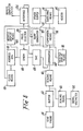
- Fig. 8 shows a further block diagram of a control unit according to a preferred embodiment of the present invention.
- Fig. 9 shows a schematic circuit diagram of a control unit according to one preferred embodiment of the present invention.
- Fig. 10 shows a schematic circuit diagram of a control unit according to another preferred embodiment of the present invention.
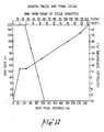
- Figs. 11 and 12 show preferred freeze/thaw temperature cycles for semen and embryo specimens respectively.
- Fig. 1 shows a cryo-cell assembly shown generally at 10 standing in a flask of LN2.
- the cryo-cell assembly comprises an inner core member 11 and an outer member 12.
- Inner core member 11 comprises a substantially cylindrical member formed of high grade aluminium and will be further described with reference to figures 2-6.
- Outer member 12 comprises a tubular member having a substantially annular cross-section formed of copper.
- the outer and inner core members are separated by a thermally insulating material 13.
- the insulating material 13 may comprise a selected insulating grade foam.
- the insulating material 13 may be injected into the substantially annular cavity between the outer and inner members.
- Outer member 12 includes a cap or base also formed of copper (not shown) fitted at its lower end.
- a sealing member 14 adapted to minimize contamination of the insulating material 13 is applied to the annular opening at the top of the cell assembly.
- Core member 11 includes a heater coil 15 wound around its outer wall.
- Heater coil 15 comprises a 7 meter strand of plastics coated 23 gauge ni-chrome wire (4.3 ohms/m) with total resistance of 30.lohms seated in a helical groove formed in the wall of the core member.
- the two ends of the heater coil 15 are passed through outer member 12 to terminals 16, 17 respectively for connection to a suitable supply of electric currents via leads 16a, 17a.
- the cryo-cell assembly is shown with straws 18, 19 inserted into the core member 11.
- One of the straws 18, 19 may hold a temperature sensor such as a diode string.
- each straw (including the temperature sensor) preferably is located in a common isotherm so that each straw is subjected to the same or substantially similar temperature environment.
- the cryo-cell is placed in a Dewar flask of liquid nitrogen (LN2).
- LN2 liquid nitrogen
- Figs. 2-6 show alternative embodiments for the inner core member 11.
- the core member of figure 2 comprises a thick walled tubular member 20 formed of high thermally conductive aluminium. Evenly spaced slots 21 are milled longitudinally or extruded on the internal wall of the core member. Each slot may be silled to a depth and width of 3mm. The slots will accept 2mm specimen straws. One slot may be slightly larger than the rest to accept the temperature sensing tube or straw.
- the base of the core member may be capped to prevent liquids and other contaminants penetrating into the insulating layer.
- a support frame made of a suitable material such as stainless steel or plastics may be inserted into the core member for supporting the straws.
- the support frame may comprise an elongate member with a handle at one end and a plurality of radially extending supports or fingers at the opposite end, for supporting the straws.
- a pair of parallel helical grooves 22, 23 are formed in the external surface of the core member for receiving the heater coils.
- the grooves preferably have a depth of .5mm and a pitch of 2 per cm each.
- the core member of figure 3 comprises a thickwalled tubular member 30 formed of high thermally conductive aluminium. Evenly spaced slots 31 for specimen strains are milled on the outside wall or extruded to a width and depth of 3mm. One slot is slightly larger to accept the temperature sensor.
- An aluminium sleeve member 32 is fitted over the core member 30 such that the core member 30 is able to move freely up and down with respect to the sleeve member 32.
- the core member 30 includes a stainless steel base plate (not shown) for supporting specimen strains.
- a wire frame handle (not shown) may be attached to the core member to facilitate extraction of the core and straws.
- a pair of parallel helical grooves 33, 34 are formed in the external surface of the sleeve member for receiving the heater coils.
- Sleeve member 32 is capped at the bottom to minimize penetration of liquid into the insulating layer.
- a 3mm aluminium tube 35 is attached along the inside wall of the sleeve member 32 so that it meshes with one of the slots 31 in core member 30. This tube may be used to house the temperature sensor.
- the core member of figure 4 comprises a thickwalled tubular member 40 formed of high thermally conductive aluminium. Evenly spaced substantially parallel holes 41 are drilled longitudinally around the perimeter of the core member 40 for receiving specimen straws. A pair of parallel helical grooves 42, 43 are formed in the external surface of the core member for receiving heater coils.
- the core member of figure 5 comprises a member 150 formed of high thermally conductive aluminium. Evenly spaced substantially parallel holes 151 are drilled longitudinally in the member for receiving ampules carrying specimens. A smaller hole 152 is formed longitudinally in the member 150 for housing the temperature sensor. A pair of parallel helical grooves 153, 154 are formed in the external surface of the core member for receiving heater coils.
- the core member of figure 6 comprises a tubular member 160 formed of high thermally conductive aluminium.
- a single bore 161 is formed longitudinally in the member for receiving larger specimens.
- a pair of parallel helical grooves 162, 163 are formed in the external surface of the core member for receiving heater coils.
- control unit supplying electrical power 50 to the heater 51 includes heating control means 52 triggered by a comparator means 53.
- Comparator means 53 receives a signal representing 'actual' temperature from temperature sensing means 54 via buffer means 55.
- the control unit includes display means 56 for displaying the sensed or actual temperature.
- Comparator means 53 also receives a signal representing desired temperature from processing means 57 via Digital to Analogue convertor (DAC) 58.
- Processing means 57 receives information regarding 'desired' temperature from one or more programmes stored in storage means 58a.
- Clock 59 provides clock pulses to processing means 57.
- FIG. 8 shows in greater detail a preferred form of control unit according to the present invention.
- the control unit shown in figure 8 includes a temperature signal comparator 60 receiving an 'actual' temperature signal from temperature probe 61 via buffer 62 and scaling means 63.
- Temperature display is provided by a digital voltmeter 64 connected to the output of buffer 62 via scaling means 65.
- Comparator 60 receives a 'desired' temperature signal from EPROM 66 via DAC 67.
- EPROM 66 is driven by an address generator 68 and clock means 69.
- Address display means 105 is also driven by address generator 68.
- the control unit includes program selector 70 for selecting one of the temperature programs or cycles stored in EPROM 66.
- the output of temperature comparator 60 is used to control switching means 71 via pulse width modulator circuit 72.
- Pulse width modulator circuit 72 comprises ramp generator 73 and comparator 74.
- the output of comparator 74 drives switching means 71 for controlling supply of power to heater 75.
- Hot/cold display means 76 is connected to the output of temperature comparator 60 for displaying when the 'actual' temperature is above (hot) or below (cold) the 'desired' temperature in a given program cycle.
- the control unit of the present invention may be connected to a remote computer system via a suitable interface 201.
- Interface 201 may include a serial socket connection such an an RS232.
- FIG 9 there is shown a schematic circuit diagram of one form of control unit according to the present invention.
- the control unit includes a temperature probe comprising a string of diodes 80.
- Each diode may comprise a small glass encapsulated silicon device having good temperature sensitivity such as a circuit type AB203.
- the diodes may be batch selected for this purpose.
- the string of diodes may be inserted into a specimen straw and placed into the core member of the cryo-cell assembly previously described.
- a suitable biasing current eg. 1uA may be applied to the string of diodes 80 via a constant current source shown generally at 81.
- Current source 81 comprises a suitably biased field effect transistor F1 chosen for its pinch off temperature stability, such as a circuit type PN 4360.
- junction temperature of each diode changes so also does the energy of charge carriers in the diode which leads to a change in the forward bias voltage across each diode junction.
- a measure of the junction temperature may be obtained.
- the voltage across the diodes 80 is applied to the input of buffer amplifier 82 which comprises a type with FET inputs.
- the output of buffer 82 is applied via scaling amplifier 83 to a temperature display device such as a digital voltmeter.
- Comparison circuit 85 includes a current summing junction 86 at the inverting input of amplifier 87.
- the summing junction receives positive current from the scaling amplifier 84 and negative current input from digital to analogue convertor (DAC) 88. When the two currents are equal and opposite the output of amplifier 87 is zero.
- DAC 88 comprises a current mode device such as a circuit type DAC 0800 driven by a 2mA reference current.
- EPROM 89 is adapted to store one or more temperature cycles or programs for freezing and/or thawing given biological materials.
- EPROM 89 may comprise a device type MM27C16.
- EPROM 89 is driven by an address generator comprising counters 90, 91.
- Each counter 90, 91 comprises a 4-bit up down counter.
- Counters 90, 91 are connected in series to provide in effect an 8-bit address generator.
- Each counter 90, 91 may comprise a device type MM74C193.
- the 8 address lines are also connected to address display 105 which includes a set of LED indicators (not shown). The LEDs display the current position in the program.
- a 3-bit thumbwheel switch 92 also is connected to EPROM 89. Thumbwheel switch 92 may be used for selecting a given temperature program or cycle stored in EPROM 89.
- Address generator counters 90, 91 are fed with clock pulses along line 93.
- Clock pulses are provided by a clock generator including an oscillator shown generally at 94.
- Oscillator 94 includes NAND gate 95 and a feedback network comprising resistors R2, R3 and capacitors C2, C3.
- the NAND gate may comprise a CMOS Schmitt trigger device type CD 4093.
- Oscillator 94 may be set to any convenient frequency, Preferably the frequency is adjustable.
- a frequency switch 96 may be provided for this purpose. In one form the oscillator frequency may be set at 3.2KHz. In another form the frequency may be 500 Hz. Frequency switch 96 may be adapted in one form to switch between two frequencies, say 500 Hz and 3.2KHz.
- the clock generator includes means for dividing the frequency of oscillator 94.
- the frequency dividing means includes divide by 2 N divider 97.
- Divider 97 may be set to divide by 214.
- Divider 97 may comprise a device type CD 4020.
- Reset switch 98 is provided for resetting counters 90, 91 and divider 97.
- Clock run/stop switch 99 is provided for stopping the clock pulses to the divider 97. Switch 99 may be used to start a program sequence or to pause in the sequence at any time.
- temperature comparison circuit 85 (amplifier, 87) will swing high (positive) or low (negative) depending on whether the 'actual' temperature is higher or lower than the 'desired' temperature.
- a pair of LEDs 100, 101 may be connected to the output of amplifier 87 to display when the 'actual' temperature is lower (too cold) or higher (too hot) than the 'desired' temperature.
- the output of amplifier 87 also drives a heater control circuit.
- the heater control circuit includes a pulse width modulator shown generally at 102 and a solid state switch including darlington transistor pair T1, T2.
- Darlington pair T1, T2 may comprise device types TIP 32C, TIP 36C respectively.
- Pulse width modulator 102 includes comparator 103 and an integrating circuit comprising resistors R4, R5 and capacitors C4, C5.
- the integrating circuit receives substantially a square signal from oscillator 94 and converts these to a rising and falling ramp signal at the inverting input of comparator 103.
- Comparator 103 compares the reference voltage at its non-inverting input representing high/low temperature with instantaneous ramp voltage at its inverting input. The output of comparator 103 is high when the reference voltage is higher than the instantaneous ramp voltage and low when the reference voltage is lower than the instantaneous ramp voltage.
- Comparator 103 is adapted to switch the darlington pair T1, T2 into conduction when its output is low and hence supply power to heater 104. When the output of comparator 103 is high, the darlington pair is turned off and no power flows to heater 104.
- Each amplifier 82, 83, 84 and 87 may comprise a device type LF412.
- Comparator 103 may comprise a device type LF411.
- NAND gates used in the circuit may comprise a device type CD4093.
- FIG 10 there is shown a schematic diagram of another form of control unit according to the present invention.
- the control unit includes a temperature probe comprising platinum wire 201.
- the platinum wire may be inserted into the core member of the cryo-cell assembly previously described in any suitable position.
- a biasing current eg. 2.5mA may be applied to platinum wire 201 via resistor R1O and variable resistor VR1.
- the voltage generated across platinum wire 201 is applied to the input of amplifier 202 (circuit type 308A). Offset of amplifier 202 is adjusted via variable resistor VR2. The output of amplifier 202 is scaled to represent actual temperature and is displayed on digital voltmeter 203 (circuit type DPM50).
- the output of amplifier 202 is connected via signal limiting circuit 204 to a comparison circuit shown generally at 205.
- Signal limiting circuit 204 includes amplifier 206 and zener diode 207.
- Signal limiting circuit 204 is adapted to limit temperature control to -44°C.
- Comparison circuit 205 includes a current summing junction 208 at the inverting input of amplifier 209.
- the summing junction receives positive current from amplifier 206 and negative current input from digital to analogue converter (DAC) 210. When the two currents are equal and opposite the output of amplifier 209 is zero.
- DAC 210 comprises a circuit type DAC 0800.
- EPROM 211 is adapted to store one or more temperature cycles or programs for freezing and/or thawing given biological materials.
- EPROM 211 comprises a device type MM 27C16.
- EPROM 211 is driven by an address generator comprising counter 212.
- Counter 212 comprises a circuit type CD4040 12 stage binary counter providing an 8 bit address to EPROM 211.
- the eight address lines are also connected to means for displaying elapsed program time.
- the latter means comprises digital to analogue converter 213 and digital voltmeter 203.
- Digital voltmeter 203 includes a turn over switch 214 for selecting display of temperature or elapsed program time. Elapsed time, is preferably displayed as a percentage of total program time.
- a 3-bit thumbwheel switch 214 is also connected to EPROM 211. Thumbwheel switch 214 may be used for selecting a given temperature program or cycle stored in EPROM 211.
- Address generator counter 212 is fed with clock pulses along line 215.
- Clock pulses are provided by a clock generator including an oscillator shown generally at 216.
- Oscillator 216 comprises a feedback network including crystal element 217, capacitors C10 and C11 and resistors R11 and R12. The feedback network is connected around an inverter provided by integrated circuit element 218.
- Integrated circuit 218 comprises a 14-stage binary counter and is used as a frequency divider.
- Divider 218 may be set to divide by 214.
- Divider 218 may comprise a device type CD 4060.
- the output of divider 218 is connected to a further divider 219.
- Divider 218 is connected to divider 219 via a run/hold switch 220.
- Switch 220 is provided for blocking clock pulses to divider 219.Switch 220 may be used to start a program sequence or to pause in the sequence at any time.
- the output of divider 219 is connected to address generator counter 212 via a turn over switch 221.
- Turn over switch 221 is adapted to adjust the frequency of pulses supplied to counter 212.
- the frequency may be selected between a fast run speed (1.7Hz) or a relatively slow run speed (0.12Hz).
- Switch 221 connects the selected frequency pulses to counter 212 via NAND gate 222.
- NAND gate 222 may be disabled via 8 input NAND gate 223.
- NAND gate 223 provides a disable pulse to NAND gate 222 when counter 212 reaches the end address of the program thereby stopping the program.
- Reset switch 224 is provided for resetting counters 212, 218 and 219.
- the output of amplifier 209 will swing high or low depending on whether the 'actual' temperature is higher or lower than the 'desired' temperature.
- the output of amplifier 209 drives a heater control circuit.
- the heater control circuit includes a pulse width modulator shown generally at 225 and a solid state switch including a darlington pair 226.
- Pulse width modulator 225 includes comparator 227 and an integrating circuit comprising resistors R13, R14 and capacitors C12, C13.
- the integrating circuit receives substantially a square signal from counter 218 and converts these to a rising and falling ramp signal at the inverting input of comparator 227.
- Comparator 227 compares the reference voltage at one of its inputs representing high/low temperature with the instantaneous ramp voltage at the other input.
- the output of comparator 103 is low when the reference voltage is higher than the ramp voltage and high when the reference voltage is lower than the instantaneous ramp voltage.
- Comparator 227 is adapted to switch the darlington pair 226 into conduction when its output is high and hence supply power to heater 240.
- Alarm circuit 228 is adapted to provide a visual or audible alarm of over or under temperature.
- Switch 229 may be used to select the visual or audible alarm.
- Alarm circuit 228 includes a pair of comparators 230, 231. The common output of comparators 230, 231 is high whenever the actual temperature is under or over the desired temperature.
- Switch 229 selectively connects the output of comparators 230, 231 to a buzzer 232 or an LED diode 233.
- a display is also included for indicating that the program is running.
- the latter includes comparator 234 and LED diode 235 connected to its output.
- the input of comparator 234 is driven by the output of NAND gate 222.
- Amplifiers 202, 206 and 208 may each comprise a device type LM308.
- Comparators 227, 230, 231 and 234 may comprise a device type LM339, quad comparator.
- the power supply for the control unit is conventional and is shown generally 236.
- the power supply includes regulators 237, 238, 239.
- Regulators 237, 239 may comprise device types LM7815 and LM7915 respectively and regulator 238 may comprise a device type LM7805.
- the power supply preferably is adapted to operate on 110/220/240 volts.
- Figures 11-12 show typical temperature freeze/thaw cycles which may be programmed into EPROM 211.
- the cryo-system of the present invention may be set up for freezing as follows:
- the cryo-cell assembly is placed in an insulated vessel and connected to the control unit.
- the insulated vessel is slowly filled with LN2. After about 3 minutes the internal temperature gradients should stablize and the system is ready for freezing.
- Specimen straws may now be inserted into the cryo-cell slots and the cell is covered with a lid.
- Switch 220 is set to run. The vessel should be inspected from time to time to ensure that sufficient coolant is present (not less than 1/4 full).
- cryo-cell assembly should be cooled before starting. This may be hastened by adding a little coolant to the inside of the cryo-cell.
- the actual straw temperature may be monitored and/or recorded during a cycle with say a voltmeter and/or chart recorder connected to the control unit temperature display output.
- the apparatus of the present invention may be adapted to precisely control freezing and thawing cycles of biological material using pre-programmed temperature functions.
- the temperature cycles can be reprogrammed to suit particular types of materials and preparations. Different temperature cycles can be stored in the memory of the unit, and any of these can be selected for use. Temperatures can be increased or decreased at specified rates; or held for a specified period of time. Such variations can occur within any program. In one form the system of the present invention can control temperatures between + 20°C and -44°C in steps of 0.25°.
- the cryo-cell and control unit of the present invention may be made highly portable and rugged for the field use. Power for the control unit may be supplied from a car battery. Consumption of coolant may be relatively low - less than 1 litre of liquid nitrogen per hour.
- the system additionally is simple and convenient to use. Sample straws can be easily loaded into and extracted from the cryo-cell.
- the cryo-cell can be readily cleaned. There are no moving parts to maintain - no mechanical pumps, or solenoid valves.
- Operation may be performed by selecting the desired cycle, pressing the reset button, and switching the system to run.
- Temperature indication may be provided by an analogue output, calibrated eg. as 1 volt per 10°C, over the range +40° to -200°C.
- a manual override may be available to stop at a particular temperature or to remove temperature control.
- the control unit may provide information on cycle time and temperature matching.
- the design of the cryo-cell may be such that each individual straw experiences the same temperature cycle, and along each straw the temperature varies by no more than say 0.2°. Specimen straws may be held in a dry environment without contamination from buffer fluids, and no frost build up.
Landscapes
- Engineering & Computer Science (AREA)
- Life Sciences & Earth Sciences (AREA)
- Physics & Mathematics (AREA)
- Health & Medical Sciences (AREA)
- General Health & Medical Sciences (AREA)
- Chemical & Material Sciences (AREA)
- Combustion & Propulsion (AREA)
- Dentistry (AREA)
- Zoology (AREA)
- Wood Science & Technology (AREA)
- Environmental Sciences (AREA)
- General Engineering & Computer Science (AREA)
- Thermal Sciences (AREA)
- Mechanical Engineering (AREA)
- Analytical Chemistry (AREA)
- Pathology (AREA)
- Immunology (AREA)
- General Physics & Mathematics (AREA)
- Biochemistry (AREA)
- Investigating Or Analysing Biological Materials (AREA)
Description
- The present invention relates to the field of cryo-preservation. In particular the present invention relates to a system suitable for deep freezing and thawing living biological material.
- Freezing and thawing of living biological materials between room temperature and say -190°C (temperature of liquid nitrogen) requires considerable care and control if the living integrity of the material is to be maintained.
- Samples of materials such as semen are typically frozen in straws (approximately 2mm diameter and 130mm length) so that each sperm cell is in close proximity to the walls of the straw through which cooling is performed.
- To avoid or alleviate thermal shock at critical points in the freezing cycle changes in temperature must be carefully controlled.
- One particular problem associated with freezing of tissue is the damaging formation of ice crystals. These may destroy cells membranes and even cell nuclei to the extent that recovery after thawing is not possible. To avoid such damage, water is sometimes removed from cells or buffered with antifreeze formulae.
- Nevertheless precise control over the freezing cycle is required. Moreover a different freezing cycle is required for different kinds of tissues. For example, semen is often buffered so that its freezing point is reduced. Cooling rate is slowed during the crossing of 3 to -10°C to ensure formation of only small elastic crystals.
- Embryos are sometimes dehydrated at low temperatures and this requires constant temperature of -6°C for approximately 30 minutes. Other tissues such as liver, spleen, glandular material, blood fractions and botanical "gene bank" material all have specific freezing requirements.
- Apparatus for performing such freezing cycles is known. However currently existing apparatus is both expensive and bulky. Existing apparatus of this type therefore is generally location based, and is not readily adapted to portable or field use. Moreover, the demand for such apparatus has expanded greatly. In particular there is a need for compact apparatus which may be portable so that a collector can freeze specimens in the 'field'.
- A further disadvantage of certain prior art machines concerns their reliability. Apparatus which utilizes moving parts such as mechanical valves for injecting liquid nitrogen (LN₂) etc may be prone to breakdown. Moreover such apparatus consumes relatively large quantities of LN₂, eg 10-15 litres per cycle.
Freezing apparatus is known (from E-A 117037) in which there are at least two different heat transfer components and in which thetubes 1 are cooled differentially. This apparatus has the disadvantage that the isotherms in the apparatus do not lie substantially along concentric cylindrical surfaces and that as a result of this heat flow from the tubes is not uniformly radial. - It is an object of the present invention to alleviate the disadvantages of the prior art. It is a further object of the present invention to provide apparatus for freezing and/or thawing biological material which may be constructed in compact dimensions, thus making it suitable for field work and other applications where portability is desirable. It is a still further object of the present invention to provide such apparatus at significantly lower cost relative to existing apparatus. At the very least the apparatus of the present invention should provide the public with a choice.
- The apparatus of the present invention is based on the thermal bridge principle, ie. the apparatus operates by locating a heat source and a heat sink in heat conducting relationship with the biological material to be processed.
- The apparatus of the present invention includes a cryo-cell assembly. The cryo-cell assembly may include a space for receiving biological material to be processed. The cryo-cell assembly preferably includes a source of heat positioned in heat conducting relationship with said space.
- The cryo-cell assembly of the present invention may be provided in any convenient form. The cryo-cell assembly preferably is adapted to generate substantially concentric isotherms within the space for receiving biological material.
- The cryo-cell assembly preferably comprises a plurality of nested members. The assembly may include an innermost or core member, a thermally insulating layer and an outer member surrounding the insulating layer. The innermost or core member may be arranged in heat conducting relationship with the space for receiving biological material. The core member preferably comprises a tubular member. The core member may include one or more slots formed, about the perimeter of the core member. The slots preferably extend longitudinally along the core member. The slots may be formed in the inner or outer wall surface of the core member.
- The inner core member may be formed of any suitable material. The inner core member may be formed of a material having good thermal conductivity such as copper, aluminium or silver. Good grade aluminium (ie. one having high purity) is preferable. The inner core member may be formed in any suitable manner eg. by extrusion or machining. The slots may be formed with the core member or they may be machined therein after forming.
- Preferably the slots are substantially evenly spaced around the perimeter of the core member. The or each slot may be adapted to accept 2mm diameter specimen straw. In one form the slots may be milled on the internal wall of the core member. The slots may be milled to a depth and width of approximately 3mm. One slot may be formed slightly larger than the others for accepting a temperature sensor.
- Where the slots are formed on an external wall of the core member, the assembly may include an intermediate member surrounding the core member. The intermediate member preferably comprises a tubular member. The intermediate member may be arranged in heat conducting relationship with the core member.
- The intermediate member preferably is slidably fitted over the inner core member. The inner core member may be slidable relative to the intermediate member to facilitate removal and placement of samples.
- A suitable base member may be attached to one (the lower) end of the inner core member or to the intermediate member. The base member may be adapted to support specimen straws and/or to prevent liquids or other materials penetrating into the insulating layer of the assembly. The supporting base preferably comprises a flat plate. The plate may be approximately circular and of a diameter similar to the internal diameter of the intermediate member.
- A suitable handle may be attached to the core member to facilitate its removal from the assembly. The handle may comprise eg. a wire frame bent to an inverted U shape and held to the core member. The handle and supporting base member preferably comprise stainless steel.
- Where slots are formed on the internal wall of the core member, the intermediate member may be dispensed with. Specimen straws may be placed into and removed from the assembly without moving the inner core member. A suitable support frame may be provided for supporting specimen straws. The support frame may be adapted to slide into the core member. The support frame may include a handle to facilitate manipulation of specimen straws.
- In one form the support frame may comprise an elongate member having a plurality of support elements at one end thereof. The support elements may extend radially from the elongate member and substantially perpendicular to the elongate member. Each support element may be adapted to engage and support the lower end of a specimen straw.
- The cryo-cell assembly includes heat generating means. The heat generating means may be adapted to surround the intermediate member and/or the inner core member. The heat generating means preferably includes a heater element adapted to surround the intermediate member and/or the inner core member.
- In one form the heat generating means comprises a heater element wound around the external wall of the intermediate member. Where specimen receiving slots are formed on the internal wall of the core member the heater element may be wound directly onto the external surface of the core member. The heater element preferably comprises resistance wire such as nichrome wire. The resistance wire element may be wound around the intermediate member with uniform spacing between the windings. The heater element preferably comprises a pair of windings having parallel windings evenly spaced with current passing in opposite directions to minimize magnetic field effects in the vicinity of the heater element and specimen.
- The intermediate member may include a pair of helical grooves cut into its external wall surface for retaining the heater element. The helical grooves may be substantially uniformally distributed over the length of the intermediate member. In one form the helical grooves may comprise a pair of parallel threads having a pitch of 2 per cm each and a depth of 0.5 mm. The resistance wire may be wound into one of the grooves and returned along the other groove to minimize the previously noted magnetic field effects. In one form the resistance of the heating element may be approximately 30 ohms.
- The thermally insulating layer may be adapted to surround the heater element. The insulating layer may be provided in any suitable manner. The insulating layer may comprise wood, felt, foam or other suitable material. The insulating layer may be formed in any suitable form. The insulating layer may comprise a sleeve of selected grade insulating material. The grade of insulating material may be selected to provide the optimum flow rate of heat between the core member and outer member. In one form the insulating material may be selected to have a heat conduction of 1mW/cm°C. The insulating layer may be wound evenly around the intermediate member or be pre-formed and fitted over the intermediate member. Alternatively the insulating layer may be injection molded into the cavity between the intermediate member and the outer member of the cryo-cell assembly.
- The intermediate member and insulating layer may be firmly fitted into the outer member. After fitment, the gap formed between the top edges of the intermediate and outer members (annular where the assembly is cylindrical) preferably is sealed to minimize penetration of moisture into the insulating layer. A pair of connecting leads for carrying current to the heater windings may be passed through the seal.
- The outer member which may comprise the housing of the cryo-cell assembly preferably comprises a tubular member surrounding the insulating layer. The outer member preferably includes a base. The base may comprise a plate or a cap member fitted at one end of the outer member. The plate preferably is welded or soldered across the opening with suitable solder material. The cap preferably is retained in the end of the outer member by means of an interference fit, eg. the cap may be pressure fitted or crimped onto the end of the outer member.
- The outer member or housing preferably comprises a material having good thermal conductivity. Copper or high purity aluminium is preferable for this purpose. The outer member or housing may be formed in any convenient manner eg. by extrusion or machining.
- The nested members of the cryo-cell assembly may comprise substantially cylindrical tubular members. The tubular members preferably are concentric. The arrangement preferably is such that heat flow is uniformly radial and layers are cylindrical isotherms. In particular all specimen and the temperature sensors may have the same temperature both around the core member and along it.
- The cryo-cell assembly of the present invention may be formed with any suitable dimensions. Preferably the cryo-cell assembly of the present invention is of the order of several centimeters in diameter (4-5cm) and of the order of 15 cm in height.
- A closure may be provided for closing the top of the cryo-cell assembly. The closure may be opened to permit insertion of monitoring devices and/or application of additional coolant to the core for fast cooling. The closure cap may be formed of any suitable material, preferably stainless steel. The closure cap may include an insulated handle.
- The cryo-cell assembly may be provided with a suitable handle. The handle preferably is insulated to facilitate handling of the assembly.
- The cryo-cell assembly of the present invention is adapted to be placed into a flask or cup filled with LN₂ which acts as a heat sink. The freezing rate may be controlled by warming the heating element.
- The cryo-system of the present invention may include a control unit for controlling the freezing cycle. The control unit preferably is programmable. The control unit may be adapted to adjust the level of current supplied to the heater windings.
- The control unit preferably incorporates feedback means for comparing the actual temperature at the core of the cryo-cell assembly with the desired temperature.
- The control unit includes temperature sensing means. The temperature sensing means includes a temperature sensing element. The temperature sensing element may be provided in any suitable manner. Preferably the temperature sensing element comprises a resistance element such as platinum wire or a string of diodes connected in series. The sensing element may be inserted into a straw of the kind used for storing specimens. Where diodes are used the diodes preferably are spaced substantially uniformly along the length of the straw. The straw may be placed in a slot of the core member in the manner of the specimen.
- A relatively low but constant biasing current, say 2.5mA may be passed through the resistance element. A relatively lower biasing current, say 1uA, may be passed through the diodes. It has been found that the diodes have good temperature sensitivity and fairly linear response over the operating temperature range at relatively low current levels.
- A constant current source may be used to supply biasing current to the temperature sensing element. The constant current source may be generated by any suitable means. In one form the current source may include a resistor. The resistor preferably exhibits a low temperature coefficient. Alternatively the constant current source may be generated by means of a suitably biased field effect transistor. The temperature sensing means may include amplifying means for amplifying the voltage generated across the temperature sensing element. The amplifying means preferably comprises an operational amplifier with FETs at its input.
- A temperature display means may be operatively connectable to the temperature sensing means. The display means may include scaling means. The scaling means may be provided in any suitable manner. The scaling means preferably comprises an operational amplifier. The gain and off-set of the operational amplifier may be adjustable by means of adjustable elements such as potentiometers.
- The temperature display means preferably includes a display element such as a voltmeter. A digital voltmeter is preferred for this purpose.
- The control unit may be adapted to generate a signal representing the desired temperature. The desired temperature generally will be a time dependent variable. It is desirable to vary the temperature cycle of the cryo-cell assembly according to the nature of the biological material being frozen.
- The control unit preferably is arranged such that the temperature cycle may be readily changed or reprogrammed. The control unit may include digital processing means for storing one or more temperature cycle programs.
- The control unit preferably includes clock means for providing timing pulses to the processing means. The clock means may be provided in any suitable manner. The clock means preferably includes an oscillator. In one form the oscillator may comprise an inverting amplifier and associated feedback circuit. The feedback circuit may include an RC network or a crystal element. The crystal element may be adapted to oscillate at a frequency of 3.58MHz. Preferably the inverting amplifier comprises a Schmitt triggered CMOS NAND gate.
- The clock means may include frequency dividing means. The dividing means may comprises a divide by 2N counter. The dividing means may comprise a circuit type CD 4020 14 stage ripple counter. In one form the dividing means may be adapted to divide the clock frequency by a factor of 2¹⁴. In another form the dividing means may comprise one or more binary counters.
- The clock means preferably includes means for adjusting its frequency. The frequency adjusting means may be provided before or after the frequency dividing means. The oscillator may include a turn over switch for "fast" or "slow" clock frequency. In one form the oscillator frequencies may be scaled to provide frequencies of 3.2KHz and 500Hz respectively. In another form the oscillator frequencies may be scaled to provide frequencies of 1.7Hz and 0.12Hz respectively.
- The processing means may include an address generator for generating a binary address. In one form the address generator may be adapted to provide an 8-bit address. The address generator preferably comprises a counter having parallel outputs. A pair of 4-bit counters may be used in series for this purpose. In one form the address generator may comprise a pair of circuit type MM74C193 up/down binary counters. In another form the address generator may comprise a circuit type 4040 twelve stage binary counter. The processing means may include an address display means for displaying the address. The address display means may comprise a row of LEDs. The processing means may additionally or alternatively comprise means for displaying elapsed program time. Means for displaying elapsed program time may include a digital to analogue converter and a voltage display means such as a digital voltmeter.
- The processing means preferably includes means for selecting a particular program. The program selector may be provided in any suitable manner. In one form the means for selecting a program may comprise a binary switch, eg. a 3-bit binary switch may be used for selecting any one of up to eight programs. In one form the binary switch comprises a thumbwheel switch.
- The processing means may comprise a microprocessor or microcomputer. The processing means may alternatively comprise a digital computer remote from the control unit of the present invention. The remote computer may be connected to the control unit via a suitable interface (serial or parallel). The interface may include an RS232 socket or a suitable parallel connection. The control unit preferably includes storage means. The storage means may include a ROM (Read only Memory).
- Preferably the ROM comprises a programmable ROM. The processing means may comprise an EPROM (Erasable Programmable ROM). In one form the processing means comprises a circuit type MM 27C16 EPROM.
- Preferably the EPROM is adapted to receive an 11-bit address. The EPROM may be adapted to receive an 8-bit address signal from the address generator and a further 3-bit address signal from the program selector.
- The EPROM may be programmed in accordance with known techniques. The EPROM may be adapted to store one or more temperature cycles or programs. Any one cycle may be selected to suit a particular type of biological material or preparation or to choose between freezing and thawing. In one form up to eight different temperatures cycles or programs may be stored in the EPROM.
- The or each program may be adapted to increase or decrease temperatures at a specified rate or to hold a temperature for a specified period of time. Any number of such variations may occur within a given program or cycle. In one form the control unit may be adapted to control temperatures between 20°C and -44°C in say 0.25°C steps. In another form the control unit may be adapted to control a larger temperature range eg. between 40°C and -190°C with a higher or lower resolution per step.
- The control unit may include a digital to analogue converter (DAC). The DAC may be adapted to convert temperature signals provided in digital form by the processing means to corresponding analogue temperature signals representing desired temperature.
- The DAC may be provided in any suitable manner. The DAC preferably comprises a single integrated device. In one form the DAC may comprise an 8-bit current mode device such as a circuit type DAC 0800. In another form the DAC may comprise a
higher resolution 16 bit device. Alternatively the function of the DAC may be provided via an external computer system. - The control unit may include means for comparing the sensed temperature with the desired temperature stored in the program. The comparison means may be provided in any suitable manner. In one form the comparison means may comprise a current summing junction. The summing junction may be provided via the input of an operational amplifier.
- The output of the temperature sensing means may be connected to one input of the comparison means via suitable buffer means, such as an operational amplifier. The (analogue) output of the DAC may be connected to the second input of the comparison means. The comparison means may be adapted to provide an output signal which is proportional to the difference between the measured and the desired temperature. The output of the comparison means may be adapted for controlling a heater control means. The heater control means may comprise a switching means for switching power to the heater of the cryo-cell assembly.
- The heater control means may be provided in any suitable manner. Preferably the heater control means includes a solid state switching device. The switching device may comprise one or more power transistors or a silicon controlled rectifier (SCR). In one form the switching device comprises a power darlington.
- The heater control means may be adapted to provide continuous or switched power to the heater of the cryo-cell assembly. To minimize heat dissipation in the switching device it is preferable to switch power to the heater.
- In one form, the heater contol means may be adapted to provide pulse width modulation of the switched power to the heater. Pulse width modulation may be provided in any suitable manner. In one form the pulse width modulator may include a ramp generator and a comparator.
- The ramp generator may be provided in any suitable manner. The ramp generator may include an integrating circuit. The integrating circuit may be adapted to receive a square wave input from an oscillator. This oscillator signal may be provided by the clock means at a frequency of say 3.2KHz or 500Hz.
- The comparator of the pulse width modulator may be adapted to compare the output of the ramp generator with the reference output of the temperature comparison means.
- Whenever the reference voltage exceeds the highest ramp voltage, the comparator of the pulse width modulator may be adapted to turn off the solid state switch and hence turn off the power to the heater.
- Whenever the reference voltage falls below the lowest ramp voltage, the comparator of the pulse width modulator may be adapted to turn on the solid state switch and hence supply full power to the heater.
- When the reference voltage falls between the limits of the highest and lowest ramp voltages, the comparator of the pulse width modulator may be adapted to switch on the solid state switch for the duration of time that the reference voltage remains below the instantaneous ramp voltage.
- The above arrangement may thus be adapted to trigger the solid state switch with a pulse width modulated signal. The duration or width of the or each pulse may be determined by the instantaneous value of the reference voltage of the temperature comparison means. The heater control means preferably is arranged such that the proportion of time that the solid state switch supplies power to the heater increases as the sensed temperature decreases below the desired or programmed temperature.
- The power supply to the control unit may be provided in any suitable manner. The control unit may be mains powered or it maybe powered from an auxiliary power supply (AC or DC) eg. a car battery.
- Preferred embodiments of the present invention will now be described with reference to the accompanying drawings wherein:-
- Fig. 1 shows a cut away view of a cryo-cell assembly according to a preferred embodiment of the present invention;
- Fig. 2 shows one form of core member suitable for use with the cryo-cell of the present invention;
- Figs. 3 to 6 show alternative forms of core member suitable for use with the cryo-cell of the present invention;
- Fig. 7 shows functional or block diagram of a control unit according to a preferred embodiment of the present invention;
- Fig. 8 shows a further block diagram of a control unit according to a preferred embodiment of the present invention;
- Fig. 9 shows a schematic circuit diagram of a control unit according to one preferred embodiment of the present invention;
- Fig. 10 shows a schematic circuit diagram of a control unit according to another preferred embodiment of the present invention; and
- Figs. 11 and 12 show preferred freeze/thaw temperature cycles for semen and embryo specimens respectively.
- Fig. 1 shows a cryo-cell assembly shown generally at 10 standing in a flask of LN₂. The cryo-cell assembly comprises an inner core member 11 and an
outer member 12. - Inner core member 11 comprises a substantially cylindrical member formed of high grade aluminium and will be further described with reference to figures 2-6.
Outer member 12 comprises a tubular member having a substantially annular cross-section formed of copper. - The outer and inner core members are separated by a thermally insulating
material 13. The insulatingmaterial 13 may comprise a selected insulating grade foam. The insulatingmaterial 13 may be injected into the substantially annular cavity between the outer and inner members. -
Outer member 12 includes a cap or base also formed of copper (not shown) fitted at its lower end. A sealingmember 14 adapted to minimize contamination of the insulatingmaterial 13 is applied to the annular opening at the top of the cell assembly. - Core member 11 includes a
heater coil 15 wound around its outer wall.Heater coil 15 comprises a 7 meter strand of plastics coated 23 gauge ni-chrome wire (4.3 ohms/m) with total resistance of 30.lohms seated in a helical groove formed in the wall of the core member. - The two ends of the
heater coil 15 are passed throughouter member 12 toterminals 16, 17 respectively for connection to a suitable supply of electric currents vialeads 16a, 17a. - The cryo-cell assembly is shown with
straws straws - It will be appreciated that the above construction generates substantially cylindrical concentric isotherms within the core member. Each straw (including the temperature sensor) preferably is located in a common isotherm so that each straw is subjected to the same or substantially similar temperature environment.
- The cryo-cell is placed in a Dewar flask of liquid nitrogen (LN₂).
- Figs. 2-6 show alternative embodiments for the inner core member 11. The core member of figure 2 comprises a thick walled
tubular member 20 formed of high thermally conductive aluminium. Evenly spacedslots 21 are milled longitudinally or extruded on the internal wall of the core member. Each slot may be silled to a depth and width of 3mm. The slots will accept 2mm specimen straws. One slot may be slightly larger than the rest to accept the temperature sensing tube or straw. - The base of the core member may be capped to prevent liquids and other contaminants penetrating into the insulating layer.
- A support frame made of a suitable material such as stainless steel or plastics may be inserted into the core member for supporting the straws. The support frame may comprise an elongate member with a handle at one end and a plurality of radially extending supports or fingers at the opposite end, for supporting the straws.
- A pair of parallel
helical grooves 22, 23 are formed in the external surface of the core member for receiving the heater coils. The grooves preferably have a depth of .5mm and a pitch of 2 per cm each. - The core member of figure 3 comprises a thickwalled
tubular member 30 formed of high thermally conductive aluminium. Evenly spaced slots 31 for specimen strains are milled on the outside wall or extruded to a width and depth of 3mm. One slot is slightly larger to accept the temperature sensor. Analuminium sleeve member 32 is fitted over thecore member 30 such that thecore member 30 is able to move freely up and down with respect to thesleeve member 32. Thecore member 30 includes a stainless steel base plate (not shown) for supporting specimen strains. A wire frame handle (not shown) may be attached to the core member to facilitate extraction of the core and straws. - A pair of parallel
helical grooves 33, 34 are formed in the external surface of the sleeve member for receiving the heater coils.Sleeve member 32 is capped at the bottom to minimize penetration of liquid into the insulating layer. - A
3mm aluminium tube 35 is attached along the inside wall of thesleeve member 32 so that it meshes with one of the slots 31 incore member 30. This tube may be used to house the temperature sensor. - A further form of core member is shown in figure 4. The core member of figure 4 comprises a thickwalled
tubular member 40 formed of high thermally conductive aluminium. Evenly spaced substantiallyparallel holes 41 are drilled longitudinally around the perimeter of thecore member 40 for receiving specimen straws. A pair of parallelhelical grooves - The core member of figure 5 comprises a
member 150 formed of high thermally conductive aluminium. Evenly spaced substantiallyparallel holes 151 are drilled longitudinally in the member for receiving ampules carrying specimens. Asmaller hole 152 is formed longitudinally in themember 150 for housing the temperature sensor. A pair of parallelhelical grooves - The core member of figure 6 comprises a
tubular member 160 formed of high thermally conductive aluminium. Asingle bore 161 is formed longitudinally in the member for receiving larger specimens. A pair of parallelhelical grooves 162, 163 are formed in the external surface of the core member for receiving heater coils. - Referring to figure 7, the control unit supplying
electrical power 50 to theheater 51 includes heating control means 52 triggered by a comparator means 53. - Comparator means 53 receives a signal representing 'actual' temperature from temperature sensing means 54 via buffer means 55. The control unit includes display means 56 for displaying the sensed or actual temperature.
- Comparator means 53 also receives a signal representing desired temperature from processing means 57 via Digital to Analogue convertor (DAC) 58. Processing means 57 receives information regarding 'desired' temperature from one or more programmes stored in storage means 58a.
Clock 59 provides clock pulses to processing means 57. - Figure 8 shows in greater detail a preferred form of control unit according to the present invention. The control unit shown in figure 8 includes a
temperature signal comparator 60 receiving an 'actual' temperature signal from temperature probe 61 viabuffer 62 and scaling means 63. - Temperature display is provided by a
digital voltmeter 64 connected to the output ofbuffer 62 via scaling means 65. -
Comparator 60 receives a 'desired' temperature signal fromEPROM 66 via DAC 67.EPROM 66 is driven by anaddress generator 68 and clock means 69. Address display means 105 is also driven byaddress generator 68. The control unit includesprogram selector 70 for selecting one of the temperature programs or cycles stored inEPROM 66. - The output of
temperature comparator 60 is used to control switching means 71 via pulse width modulator circuit 72. Pulse width modulator circuit 72 comprises ramp generator 73 and comparator 74. The output of comparator 74 drives switching means 71 for controlling supply of power to heater 75. - Hot/cold display means 76 is connected to the output of
temperature comparator 60 for displaying when the 'actual' temperature is above (hot) or below (cold) the 'desired' temperature in a given program cycle. - The control unit of the present invention may be connected to a remote computer system via a
suitable interface 201.Interface 201 may include a serial socket connection such an an RS232. - Referring to figure 9, there is shown a schematic circuit diagram of one form of control unit according to the present invention.
- The control unit includes a temperature probe comprising a string of
diodes 80. Each diode may comprise a small glass encapsulated silicon device having good temperature sensitivity such as a circuit type AB203. The diodes may be batch selected for this purpose. - The string of diodes may be inserted into a specimen straw and placed into the core member of the cryo-cell assembly previously described.
- A suitable biasing current eg. 1uA may be applied to the string of
diodes 80 via a constant current source shown generally at 81. Current source 81 comprises a suitably biased field effect transistor F1 chosen for its pinch off temperature stability, such as a circuit type PN 4360. - It will be appreciated that as the junction temperature of each diode changes so also does the energy of charge carriers in the diode which leads to a change in the forward bias voltage across each diode junction. By measuring the resulting voltage across the
diodes 80, a measure of the junction temperature may be obtained. - The voltage across the
diodes 80 is applied to the input of buffer amplifier 82 which comprises a type with FET inputs. The output of buffer 82 is applied via scaling amplifier 83 to a temperature display device such as a digital voltmeter. - The output of buffer 82 is further applied via scaling
amplifier 84 to a comparison circuit shown generally at 85.Comparison circuit 85 includes a current summingjunction 86 at the inverting input ofamplifier 87. - The summing junction receives positive current from the scaling
amplifier 84 and negative current input from digital to analogue convertor (DAC) 88. When the two currents are equal and opposite the output ofamplifier 87 is zero.DAC 88 comprises a current mode device such as a circuit type DAC 0800 driven by a 2mA reference current. -
DAC 88 is fed with digital data stored inEPROM 89.EPROM 89 is adapted to store one or more temperature cycles or programs for freezing and/or thawing given biological materials.EPROM 89 may comprise a device type MM27C16. -
EPROM 89 is driven by an addressgenerator comprising counters counter Counters counter display 105 which includes a set of LED indicators (not shown). The LEDs display the current position in the program. - A 3-bit thumbwheel switch 92 also is connected to
EPROM 89. Thumbwheel switch 92 may be used for selecting a given temperature program or cycle stored inEPROM 89. - Address generator counters 90, 91 are fed with clock pulses along
line 93. Clock pulses are provided by a clock generator including an oscillator shown generally at 94.Oscillator 94 includesNAND gate 95 and a feedback network comprising resistors R₂, R₃ and capacitors C₂, C₃. The NAND gate may comprise a CMOS Schmitt trigger device type CD 4093.Oscillator 94 may be set to any convenient frequency, Preferably the frequency is adjustable. A frequency switch 96 may be provided for this purpose. In one form the oscillator frequency may be set at 3.2KHz. In another form the frequency may be 500 Hz. Frequency switch 96 may be adapted in one form to switch between two frequencies, say 500 Hz and 3.2KHz. - The clock generator includes means for dividing the frequency of
oscillator 94. The frequency dividing means includes divide by 2N divider 97. Divider 97 may be set to divide by 2¹⁴. Divider 97 may comprise a device type CD 4020. -
Reset switch 98 is provided for resettingcounters stop switch 99 is provided for stopping the clock pulses to the divider 97.Switch 99 may be used to start a program sequence or to pause in the sequence at any time. - It will be appreciated that the output of temperature comparison circuit 85 (amplifier, 87) will swing high (positive) or low (negative) depending on whether the 'actual' temperature is higher or lower than the 'desired' temperature. A pair of
LEDs amplifier 87 to display when the 'actual' temperature is lower (too cold) or higher (too hot) than the 'desired' temperature. - The output of
amplifier 87 also drives a heater control circuit. The heater control circuit includes a pulse width modulator shown generally at 102 and a solid state switch including darlington transistor pair T₁, T₂. Darlington pair T₁, T₂ may comprise device types TIP 32C, TIP 36C respectively. -
Pulse width modulator 102 includes comparator 103 and an integrating circuit comprising resistors R₄, R₅ and capacitors C₄, C₅. The integrating circuit receives substantially a square signal fromoscillator 94 and converts these to a rising and falling ramp signal at the inverting input of comparator 103. - Comparator 103 compares the reference voltage at its non-inverting input representing high/low temperature with instantaneous ramp voltage at its inverting input. The output of comparator 103 is high when the reference voltage is higher than the instantaneous ramp voltage and low when the reference voltage is lower than the instantaneous ramp voltage.
- Comparator 103 is adapted to switch the darlington pair T₁, T₂ into conduction when its output is low and hence supply power to
heater 104. When the output of comparator 103 is high, the darlington pair is turned off and no power flows toheater 104. - Each
amplifier - Referring to figure 10 there is shown a schematic diagram of another form of control unit according to the present invention.
- The control unit includes a temperature probe comprising
platinum wire 201. The platinum wire may be inserted into the core member of the cryo-cell assembly previously described in any suitable position. - A biasing current eg. 2.5mA may be applied to
platinum wire 201 via resistor R1O and variable resistor VR1. - The voltage generated across
platinum wire 201 is applied to the input of amplifier 202 (circuit type 308A). Offset ofamplifier 202 is adjusted via variable resistor VR2. The output ofamplifier 202 is scaled to represent actual temperature and is displayed on digital voltmeter 203 (circuit type DPM50). - The output of
amplifier 202 is connected viasignal limiting circuit 204 to a comparison circuit shown generally at 205. Signal limitingcircuit 204 includesamplifier 206 and zener diode 207. Signal limitingcircuit 204 is adapted to limit temperature control to -44°C. -
Comparison circuit 205 includes a current summingjunction 208 at the inverting input ofamplifier 209. The summing junction receives positive current fromamplifier 206 and negative current input from digital to analogue converter (DAC) 210. When the two currents are equal and opposite the output ofamplifier 209 is zero.DAC 210 comprises a circuit type DAC 0800. -
DAC 210 is fed with digital data stored inEPROM 211.EPROM 211 is adapted to store one or more temperature cycles or programs for freezing and/or thawing given biological materials.EPROM 211 comprises a device type MM 27C16. -
EPROM 211 is driven by an addressgenerator comprising counter 212.Counter 212 comprises acircuit type CD4040 12 stage binary counter providing an 8 bit address toEPROM 211. The eight address lines are also connected to means for displaying elapsed program time. The latter means comprises digital toanalogue converter 213 anddigital voltmeter 203.Digital voltmeter 203 includes a turn overswitch 214 for selecting display of temperature or elapsed program time. Elapsed time, is preferably displayed as a percentage of total program time. - A 3-
bit thumbwheel switch 214 is also connected toEPROM 211.Thumbwheel switch 214 may be used for selecting a given temperature program or cycle stored inEPROM 211. -
Address generator counter 212 is fed with clock pulses alongline 215. Clock pulses are provided by a clock generator including an oscillator shown generally at 216. Oscillator 216 comprises a feedback network including crystal element 217, capacitors C10 and C11 and resistors R11 and R12. The feedback network is connected around an inverter provided byintegrated circuit element 218.Integrated circuit 218 comprises a 14-stage binary counter and is used as a frequency divider.Divider 218 may be set to divide by 2¹⁴.Divider 218 may comprise a device type CD 4060. The output ofdivider 218 is connected to afurther divider 219.Divider 218 is connected to divider 219 via a run/hold switch 220.Switch 220 is provided for blocking clock pulses todivider 219.Switch 220 may be used to start a program sequence or to pause in the sequence at any time. - The output of
divider 219 is connected to addressgenerator counter 212 via a turn overswitch 221. Turn overswitch 221 is adapted to adjust the frequency of pulses supplied to counter 212. - The frequency may be selected between a fast run speed (1.7Hz) or a relatively slow run speed (0.12Hz).
Switch 221 connects the selected frequency pulses to counter 212 viaNAND gate 222.NAND gate 222 may be disabled via 8input NAND gate 223.NAND gate 223 provides a disable pulse toNAND gate 222 whencounter 212 reaches the end address of the program thereby stopping the program. -
Reset switch 224 is provided for resettingcounters - The output of
amplifier 209 will swing high or low depending on whether the 'actual' temperature is higher or lower than the 'desired' temperature. The output ofamplifier 209 drives a heater control circuit. The heater control circuit includes a pulse width modulator shown generally at 225 and a solid state switch including adarlington pair 226. -
Pulse width modulator 225 includes comparator 227 and an integrating circuit comprising resistors R13, R14 and capacitors C12, C13. The integrating circuit receives substantially a square signal fromcounter 218 and converts these to a rising and falling ramp signal at the inverting input of comparator 227. - Comparator 227 compares the reference voltage at one of its inputs representing high/low temperature with the instantaneous ramp voltage at the other input. The output of comparator 103 is low when the reference voltage is higher than the ramp voltage and high when the reference voltage is lower than the instantaneous ramp voltage.
- Comparator 227 is adapted to switch the
darlington pair 226 into conduction when its output is high and hence supply power toheater 240. - An alarm circuit is shown generally at 228.
Alarm circuit 228 is adapted to provide a visual or audible alarm of over or under temperature.Switch 229 may be used to select the visual or audible alarm.Alarm circuit 228 includes a pair ofcomparators comparators - Switch 229 selectively connects the output of
comparators buzzer 232 or anLED diode 233. - A display is also included for indicating that the program is running. The latter includes
comparator 234 andLED diode 235 connected to its output. The input ofcomparator 234 is driven by the output ofNAND gate 222. -
Amplifiers Comparators - The power supply for the control unit is conventional and is shown generally 236. The power supply includes
regulators Regulators regulator 238 may comprise a device type LM7805. The power supply preferably is adapted to operate on 110/220/240 volts. - Figures 11-12 show typical temperature freeze/thaw cycles which may be programmed into
EPROM 211. - The cryo-system of the present invention may be set up for freezing as follows:
- Power is connected to the control unit and switched on. A temperature cycle is selected on
thumbwheel switch 214 and run/hold switch 220 is set to hold.Switch 224 is reset and the appropriate program speed is selected onswitch 221. - The cryo-cell assembly is placed in an insulated vessel and connected to the control unit. The insulated vessel is slowly filled with LN₂. After about 3 minutes the internal temperature gradients should stablize and the system is ready for freezing.
- Specimen straws may now be inserted into the cryo-cell slots and the cell is covered with a lid.
Switch 220 is set to run. The vessel should be inspected from time to time to ensure that sufficient coolant is present (not less than 1/4 full). - When
display 235 has stopped flashing the cycle is complete.Digital voltmeter 203 should then be displaying 100% elapsed program time confirming that the cycle is complete. The straws may be extracted and transferred to storage, although this is not urgent. - The procedure for thawing is similar but the cryo-cell assembly should be cooled before starting. This may be hastened by adding a little coolant to the inside of the cryo-cell.
- The actual straw temperature may be monitored and/or recorded during a cycle with say a voltmeter and/or chart recorder connected to the control unit temperature display output.
- The apparatus of the present invention may be adapted to precisely control freezing and thawing cycles of biological material using pre-programmed temperature functions.
- The temperature cycles can be reprogrammed to suit particular types of materials and preparations. Different temperature cycles can be stored in the memory of the unit, and any of these can be selected for use. Temperatures can be increased or decreased at specified rates; or held for a specified period of time. Such variations can occur within any program. In one form the system of the present invention can control temperatures between + 20°C and -44°C in steps of 0.25°.
- Further advantages of the system include:
- The cryo-cell and control unit of the present invention may be made highly portable and rugged for the field use. Power for the control unit may be supplied from a car battery. Consumption of coolant may be relatively low - less than 1 litre of liquid nitrogen per hour.
- The system additionally is simple and convenient to use. Sample straws can be easily loaded into and extracted from the cryo-cell. The cryo-cell can be readily cleaned. There are no moving parts to maintain - no mechanical pumps, or solenoid valves.
- Operation may be performed by selecting the desired cycle, pressing the reset button, and switching the system to run. Temperature indication may be provided by an analogue output, calibrated eg. as 1 volt per 10°C, over the range +40° to -200°C. A manual override may be available to stop at a particular temperature or to remove temperature control.
- The control unit may provide information on cycle time and temperature matching. The design of the cryo-cell may be such that each individual straw experiences the same temperature cycle, and along each straw the temperature varies by no more than say 0.2°. Specimen straws may be held in a dry environment without contamination from buffer fluids, and no frost build up.
- It will be appreciated that various alterations, modifications and/or additions may be introduced into the constructions and arrangements of parts previously described without departing from the ambit of the present invention.
Claims (15)
- A cryo-cell assembly (10) for freezing/thawing biological material, said assembly including a core member (30) having a substantially circular cross-section, a plurality of spaces (21) formed in said core member (30) for receiving said biological material, said core member (30) being adapted for conducting heat from said spaces to a heat sink, said assembly including heat generating means (15) in heat conducting relationship with said spaces (21) and said spaces (21) being arranged such that they substantially coincide with common isotherms which lie along concentric cylindrical surfaces.
- A cryo-cell assembly according to claim 1 including an under/over temperature alarm.
- A cryo-cell assembly according to claim 1 or 2 including an outer member (12) spaced from said core member (30) and an insulating layer (13) intermediate said core member (30) and said outer member (12).
- A cryo-cell assembly according to claim 3 wherein said core member (30) and said outer member (12) are tubular.
- A cryo-cell assembly according to claim 4 wherein said spaces comprise slots (21) formed longitudinally in said core member (30) suitable for receiving straws bearing specimens of biological material.
- A cryo-cell assembly according to claim 5 wherein said slots (21) are formed around a perimeter of the tubular core member (30).
- A cryo-cell assembly according to any one of the preceding claims wherein said core member (30) comprises high purity aluminium.
- A cryo-cell assembly according to any one of the preceding claims wherein said heat generating means comprises a heater element (15).
- A cryo-cell assembly according to claim 8 wherein said heater element (15) is wound around said core member (30).
- A cryo-cell assembly according to any one of the preceding claims wherein said heat generating means (15) includes a supply unit (50) for supplying power to said heat generating means (15) in accordance with a desired temperature cycle.
- A cryo-cell assmbly according to claim 10 characterized in that said supply unit is capable of supplying electrical power and said heat generating means comprises an electrically operated heater element.
- A cryo-cell assembly according to claim 11 characterized in that said supply unit comprises:actual temperature sensing means for sensing the actual temperature of an environment associated with said heater element;memory means for storing the desired temperature cycle;comparator means for comparing the desired temperature and the actual temperature; andheat control means responsive to the comparator means for supplying electrical power to said heater element whenever the actual temperature falls below the desired temperature.
- A cry-cell assembly according to claim 12 wherein said memory means comprises a read only memory (66) and said desired temperature cycle is stored in said memory in digital form.
- A cry-cell assmbly according to claim 13 further including digital-to-analogue conversion means (67) for converting the stored temperature cycle to analogue form prior to comparison with the actual temperature.
- A cry-cell assembly according to any one of claims 11-14 wherein the supply of electrical power to said heat generating element is pulse-width modulated and the width of the pulses is controlled by the output of the comparator means.
Priority Applications (1)
| Application Number | Priority Date | Filing Date | Title |
|---|---|---|---|
| AT85308159T ATE62578T1 (en) | 1984-11-09 | 1985-11-08 | CRYOGENIC SYSTEM FOR BIOLOGICAL MATERIAL. |
Applications Claiming Priority (3)
| Application Number | Priority Date | Filing Date | Title |
|---|---|---|---|
| AU8048/84 | 1984-11-09 | ||
| AUPG804884 | 1984-11-09 | ||
| AU49497/85A AU577636B2 (en) | 1984-11-09 | 1985-11-08 | Cryostem for biological material |
Publications (3)
| Publication Number | Publication Date |
|---|---|
| EP0181235A2 EP0181235A2 (en) | 1986-05-14 |
| EP0181235A3 EP0181235A3 (en) | 1987-04-29 |
| EP0181235B1 true EP0181235B1 (en) | 1991-04-17 |
Family
ID=25628665
Family Applications (1)
| Application Number | Title | Priority Date | Filing Date |
|---|---|---|---|
| EP85308159A Expired EP0181235B1 (en) | 1984-11-09 | 1985-11-08 | Cryosystem for biological material |
Country Status (1)
| Country | Link |
|---|---|
| EP (1) | EP0181235B1 (en) |
Cited By (1)
| Publication number | Priority date | Publication date | Assignee | Title |
|---|---|---|---|---|
| DE102004047965A1 (en) * | 2004-10-01 | 2006-04-13 | Fraunhofer-Gesellschaft zur Förderung der angewandten Forschung e.V. | Cryo device and associated operating method |
Families Citing this family (9)
| Publication number | Priority date | Publication date | Assignee | Title |
|---|---|---|---|---|
| FR2602858B1 (en) * | 1986-07-28 | 1988-11-10 | Air Liquide | APPARATUS FOR FREEZING ORGANIC PRODUCTS PACKED IN FLAKES USING A CRYOGENIC LIQUID |
| CH672834A5 (en) * | 1987-01-19 | 1989-12-29 | Agrogen Stiftung | |
| JPH05502578A (en) * | 1989-08-07 | 1993-05-13 | セル・システムズ・エルティーディー | Cooling methods and equipment |
| GB9414428D0 (en) * | 1994-07-16 | 1994-09-07 | Sec Dep For Foreign And Common | Improvements in or relating to cryopreservation |
| NL1004619C2 (en) | 1996-11-26 | 1998-05-27 | Instituut Voor Dierhouderij En | Apparatus and method for freezing living cells, in particular sperm. |
| US9664431B2 (en) | 2012-03-12 | 2017-05-30 | The World Egg Bank, Inc | Cryogenic sample holder |
| US10531657B2 (en) | 2015-12-07 | 2020-01-14 | Coopersurgical, Inc. | Low temperature specimen carriers and related methods |
| CZ307834B6 (en) * | 2017-08-02 | 2019-06-12 | Bioinova, S.R.O. | A method of treating frozen samples of biological materials and equipment for doing it |
| CN117730850B (en) * | 2024-02-21 | 2024-04-19 | 吉林大学 | Pathological sampling low-temperature storage box |
Family Cites Families (9)
| Publication number | Priority date | Publication date | Assignee | Title |
|---|---|---|---|---|
| CH146662A (en) * | 1930-01-14 | 1931-04-30 | Werke Standard | For the storage of substances while maintaining a certain temperature, certain containers with insert. |
| GB1472333A (en) * | 1973-10-18 | 1977-05-04 | Max Planck Gesellschaft | Method and apparatus for producing predetermined temperatures with the aid of a cryoliquid |
| US4001944A (en) * | 1975-08-25 | 1977-01-11 | Parke, Davis & Company | Freeze-drying process |
| DE2657703C2 (en) * | 1976-12-20 | 1983-03-24 | Linde Ag, 6200 Wiesbaden | Method and device for deep freezing biological substances |
| US4117881A (en) * | 1977-06-14 | 1978-10-03 | The United States Of America As Represented By The Administrator Of The National Aeronautics And Space Administration | System for and method of freezing biological tissue |
| FR2466405A1 (en) * | 1979-09-28 | 1981-04-10 | Air Liquide | DEVICE FOR STORING PRODUCTS SUCH AS SEEDS OR THE LIKE COMPRISING A CRYOBIOLOGICAL RESERVOIR |
| FR2492210A1 (en) * | 1980-10-09 | 1982-04-16 | Applic Micro Ondes Ste Fse | Microwave heater to defrost heat sensitive frozen prod. - esp. blood plasma continuously agitates prod. intermittently exposed to irradiation |
| US4459825A (en) * | 1982-07-29 | 1984-07-17 | Crouch Michael D | Apparatus for controlled reduction in temperature and preservation of embryos in a cryogenic state |
| JPS6056B2 (en) * | 1983-01-14 | 1985-01-05 | 株式会社 ほくさん | Freezing equipment for fertilized eggs, sperm, etc. |
-
1985
- 1985-11-08 EP EP85308159A patent/EP0181235B1/en not_active Expired
Cited By (3)
| Publication number | Priority date | Publication date | Assignee | Title |
|---|---|---|---|---|
| DE102004047965A1 (en) * | 2004-10-01 | 2006-04-13 | Fraunhofer-Gesellschaft zur Förderung der angewandten Forschung e.V. | Cryo device and associated operating method |
| DE102004047965B4 (en) * | 2004-10-01 | 2007-03-01 | Fraunhofer-Gesellschaft zur Förderung der angewandten Forschung e.V. | Cryo device and associated operating method |
| US7634917B2 (en) | 2004-10-01 | 2009-12-22 | Fraunhofer-Gesellschaft Zur Forderung Der Angewandten Forschung E.V. | Cryo-device and associated operational method |
Also Published As
| Publication number | Publication date |
|---|---|
| EP0181235A2 (en) | 1986-05-14 |
| EP0181235A3 (en) | 1987-04-29 |
Similar Documents
| Publication | Publication Date | Title |
|---|---|---|
| US4712607A (en) | Cryosystem for biological material | |
| EP0181235B1 (en) | Cryosystem for biological material | |
| Hwang et al. | Measurement of heat capacity by fitting the whole temperature response of a heat-pulse calorimeter | |
| US4601587A (en) | Device and method for determining freezing points | |
| JP2628670B2 (en) | Apparatus for cooling and rapidly freezing biological samples in containers | |
| US4197866A (en) | Soil moisture sampler and controller | |
| US4845978A (en) | Determining moisture content of a medium | |
| US6326892B1 (en) | Miniaturized electronic casing for monitoring the cold chain for perishable products | |
| WO2014194022A1 (en) | Temperature-stabilized storage systems with regulated cooling | |
| EP1613937B1 (en) | Thermometer | |
| US6925873B2 (en) | Liquid helium level sensor for use in a cryogenic environment and method for assembling same | |
| Moldover et al. | Specific Heat of He 3 and He 4 in the Neighborhood of their Critical Points | |
| JP2008175640A (en) | Refrigerant liquid level measuring device, refrigerant liquid level measuring method, and superconducting magnet device using the same | |
| Zhang et al. | A miniaturized cryoprobe for functional neuronal blockade in freely moving animals | |
| Chen et al. | Channel heat transfer in He II—Steady state orientation dependence | |
| EP0238558A1 (en) | Specimen cooling and warming apparatus and method | |
| Kadambi et al. | Current decay and temperatures during superconducting magnet coil quench | |
| JPS6459169A (en) | Characteristic measuring apparatus of superconductive material | |
| GB1578015A (en) | Indusion warmer | |
| Schmidt et al. | An absolute method for measuring the energy output of a laser | |
| CA2301408A1 (en) | System and method for determining heat transfer in an environment | |
| Talpe et al. | Cryogenic thermometry and level detection with common diodes | |
| US12262664B2 (en) | Automatic vegetation watering apparatus and method | |
| Pilla et al. | A modified dual-slope method for heat capacity measurements of condensable gases | |
| Lawn et al. | A simplified thermistor flowmeter and thermometer |
Legal Events
| Date | Code | Title | Description |
|---|---|---|---|
| PUAI | Public reference made under article 153(3) epc to a published international application that has entered the european phase |
Free format text: ORIGINAL CODE: 0009012 |
|
| AK | Designated contracting states |
Kind code of ref document: A2 Designated state(s): AT BE CH DE FR GB IT LI LU NL SE |
|
| PUAL | Search report despatched |
Free format text: ORIGINAL CODE: 0009013 |
|
| AK | Designated contracting states |
Kind code of ref document: A3 Designated state(s): AT BE CH DE FR GB IT LI LU NL SE |
|
| 17P | Request for examination filed |
Effective date: 19870326 |
|
| 17Q | First examination report despatched |
Effective date: 19890215 |
|
| RAP1 | Party data changed (applicant data changed or rights of an application transferred) |
Owner name: CRYOLOGIC PTY. LTD. |
|
| GRAA | (expected) grant |
Free format text: ORIGINAL CODE: 0009210 |
|
| AK | Designated contracting states |
Kind code of ref document: B1 Designated state(s): AT BE CH DE FR GB IT LI LU NL SE |
|
| PG25 | Lapsed in a contracting state [announced via postgrant information from national office to epo] |
Ref country code: LI Effective date: 19910417 Ref country code: CH Effective date: 19910417 Ref country code: AT Effective date: 19910417 |
|
| REF | Corresponds to: |
Ref document number: 62578 Country of ref document: AT Date of ref document: 19910515 Kind code of ref document: T |
|
| ITF | It: translation for a ep patent filed | ||
| REF | Corresponds to: |
Ref document number: 3582555 Country of ref document: DE Date of ref document: 19910523 |
|
| ET | Fr: translation filed | ||
| REG | Reference to a national code |
Ref country code: CH Ref legal event code: PL |
|
| PG25 | Lapsed in a contracting state [announced via postgrant information from national office to epo] |
Ref country code: LU Free format text: LAPSE BECAUSE OF NON-PAYMENT OF DUE FEES Effective date: 19911130 |
|
| PLBE | No opposition filed within time limit |
Free format text: ORIGINAL CODE: 0009261 |
|
| STAA | Information on the status of an ep patent application or granted ep patent |
Free format text: STATUS: NO OPPOSITION FILED WITHIN TIME LIMIT |
|
| 26N | No opposition filed | ||
| EAL | Se: european patent in force in sweden |
Ref document number: 85308159.4 |
|
| REG | Reference to a national code |
Ref country code: GB Ref legal event code: IF02 |
|
| PGFP | Annual fee paid to national office [announced via postgrant information from national office to epo] |
Ref country code: DE Payment date: 20040715 Year of fee payment: 20 |
|
| PGFP | Annual fee paid to national office [announced via postgrant information from national office to epo] |
Ref country code: NL Payment date: 20040730 Year of fee payment: 20 |
|
| PGFP | Annual fee paid to national office [announced via postgrant information from national office to epo] |
Ref country code: GB Payment date: 20040929 Year of fee payment: 20 |
|
| PGFP | Annual fee paid to national office [announced via postgrant information from national office to epo] |
Ref country code: FR Payment date: 20041008 Year of fee payment: 20 |
|
| PGFP | Annual fee paid to national office [announced via postgrant information from national office to epo] |
Ref country code: SE Payment date: 20041116 Year of fee payment: 20 |
|
| PGFP | Annual fee paid to national office [announced via postgrant information from national office to epo] |
Ref country code: BE Payment date: 20041119 Year of fee payment: 20 |
|
| PG25 | Lapsed in a contracting state [announced via postgrant information from national office to epo] |
Ref country code: GB Free format text: LAPSE BECAUSE OF EXPIRATION OF PROTECTION Effective date: 20051107 |
|
| PG25 | Lapsed in a contracting state [announced via postgrant information from national office to epo] |
Ref country code: NL Free format text: LAPSE BECAUSE OF EXPIRATION OF PROTECTION Effective date: 20051108 |
|
| BE20 | Be: patent expired |
Owner name: *CRYOLOGIC PTY. LTD Effective date: 20051108 |
|
| REG | Reference to a national code |
Ref country code: GB Ref legal event code: PE20 |
|
| NLV7 | Nl: ceased due to reaching the maximum lifetime of a patent |
Effective date: 20051108 |
|
| EUG | Se: european patent has lapsed | ||
| BE20 | Be: patent expired |
Owner name: *CRYOLOGIC PTY. LTD Effective date: 20051108 |