EP0183135A1 - Automatic cutting and winding apparatus for a web-like material such as a film - Google Patents
Automatic cutting and winding apparatus for a web-like material such as a film Download PDFInfo
- Publication number
- EP0183135A1 EP0183135A1 EP85114435A EP85114435A EP0183135A1 EP 0183135 A1 EP0183135 A1 EP 0183135A1 EP 85114435 A EP85114435 A EP 85114435A EP 85114435 A EP85114435 A EP 85114435A EP 0183135 A1 EP0183135 A1 EP 0183135A1
- Authority
- EP
- European Patent Office
- Prior art keywords
- web
- film
- swingable arm
- charging means
- core
- Prior art date
- Legal status (The legal status is an assumption and is not a legal conclusion. Google has not performed a legal analysis and makes no representation as to the accuracy of the status listed.)
- Granted
Links
- 239000000463 material Substances 0.000 title claims abstract description 39
- 238000005520 cutting process Methods 0.000 title claims abstract description 30
- 238000004804 winding Methods 0.000 title claims abstract description 29
- 238000007786 electrostatic charging Methods 0.000 claims description 29
- 239000002390 adhesive tape Substances 0.000 abstract description 4
- 230000008030 elimination Effects 0.000 abstract 1
- 238000003379 elimination reaction Methods 0.000 abstract 1
- 238000010276 construction Methods 0.000 description 5
- 238000005422 blasting Methods 0.000 description 4
- 230000033001 locomotion Effects 0.000 description 2
- 238000004519 manufacturing process Methods 0.000 description 2
- 239000000853 adhesive Substances 0.000 description 1
- 230000001070 adhesive effect Effects 0.000 description 1
- 238000007600 charging Methods 0.000 description 1
- 230000000694 effects Effects 0.000 description 1
- 238000009499 grossing Methods 0.000 description 1
- 238000012986 modification Methods 0.000 description 1
- 230000004048 modification Effects 0.000 description 1
- 238000003825 pressing Methods 0.000 description 1
- 238000006748 scratching Methods 0.000 description 1
- 230000002393 scratching effect Effects 0.000 description 1
Images


Classifications
-
- B—PERFORMING OPERATIONS; TRANSPORTING
- B65—CONVEYING; PACKING; STORING; HANDLING THIN OR FILAMENTARY MATERIAL
- B65H—HANDLING THIN OR FILAMENTARY MATERIAL, e.g. SHEETS, WEBS, CABLES
- B65H19/00—Changing the web roll
- B65H19/10—Changing the web roll in unwinding mechanisms or in connection with unwinding operations
- B65H19/20—Cutting-off the expiring web
-
- B—PERFORMING OPERATIONS; TRANSPORTING
- B65—CONVEYING; PACKING; STORING; HANDLING THIN OR FILAMENTARY MATERIAL
- B65H—HANDLING THIN OR FILAMENTARY MATERIAL, e.g. SHEETS, WEBS, CABLES
- B65H19/00—Changing the web roll
- B65H19/22—Changing the web roll in winding mechanisms or in connection with winding operations
- B65H19/26—Cutting-off the web running to the wound web roll
-
- B—PERFORMING OPERATIONS; TRANSPORTING
- B65—CONVEYING; PACKING; STORING; HANDLING THIN OR FILAMENTARY MATERIAL
- B65H—HANDLING THIN OR FILAMENTARY MATERIAL, e.g. SHEETS, WEBS, CABLES
- B65H19/00—Changing the web roll
- B65H19/22—Changing the web roll in winding mechanisms or in connection with winding operations
- B65H19/28—Attaching the leading end of the web to the replacement web-roll core or spindle
-
- B—PERFORMING OPERATIONS; TRANSPORTING
- B65—CONVEYING; PACKING; STORING; HANDLING THIN OR FILAMENTARY MATERIAL
- B65H—HANDLING THIN OR FILAMENTARY MATERIAL, e.g. SHEETS, WEBS, CABLES
- B65H2301/00—Handling processes for sheets or webs
- B65H2301/40—Type of handling process
- B65H2301/41—Winding, unwinding
- B65H2301/414—Winding
- B65H2301/41419—Starting winding process
- B65H2301/41421—Starting winding process involving electrostatic means
-
- Y—GENERAL TAGGING OF NEW TECHNOLOGICAL DEVELOPMENTS; GENERAL TAGGING OF CROSS-SECTIONAL TECHNOLOGIES SPANNING OVER SEVERAL SECTIONS OF THE IPC; TECHNICAL SUBJECTS COVERED BY FORMER USPC CROSS-REFERENCE ART COLLECTIONS [XRACs] AND DIGESTS
- Y10—TECHNICAL SUBJECTS COVERED BY FORMER USPC
- Y10S—TECHNICAL SUBJECTS COVERED BY FORMER USPC CROSS-REFERENCE ART COLLECTIONS [XRACs] AND DIGESTS
- Y10S242/00—Winding, tensioning, or guiding
- Y10S242/906—Static charger or discharger
Definitions
- the present invention relates to an automatic cutting and winding apparatus for a web-like material such as a film, which automatically cuts a web-like material such as a film and continuously performs rewinding, and which is applicable to a biaxial oriented film manufacturing system, an unoriented film manufacturing system or the like.
- a winding system for a web-like material such as a film (hereinafter called simply "film”) in which a medium for giving an adhesiveness such as an adhesive tape is not used on a core but a film is wrapped directly around a core (hereinafter called “tapeless winding system”) has been being given attention in various fields because damages of films in inner layers of a mill roll caused by unevenness of a core surface due to an adhesive tape or the like are not present and also a work of removing remaining adhesive materials upon reuse of the core is unnecessary, but there still remain problems such that scratches are generated at a cut end of a film, and therefore, development of a more complete system has been strongly desired.
- a turret type automatic cutting and winding apparatus for automatically cutting a web-like material by means of a press roll and a cutter and winding it around a core, which apparatus comprises electrostatic charging means mounted on a swingable arm or arms for giving electrostatic charge on a cut end portion of the web-like material.
- the turret type automatic cutting and winding apparatus is constructed in the above-featured manner, upon cutting a web-like material and rewinding it on a new core, the swingable arm or arms would make swing motion, electrostatic charge is given on a cut end portion of the web-like material by the electrostatic charging means mounted on the swingable arm or arms, thereby the cut end portion of the web-like material is made to adhere to the surface of the new core by an electrostatic attracting force, and simultaneously, winding of the web-like material around the new core is commenced. Therefore, slip would not occur between the surface of the new core and the cut end portion of the web-like material, and so, scratches would not be generated at the cut end portion of the web-like material.
- reference numeral 1 designates a film
- reference numeral 2 designates a new core around which a cut film is to be rewound
- this core 2 is mounted on one arm of a turret 4 so as to be rotationally driven in the direction of arrow A by means of a driving device not shown
- Reference numeral 3 designates a guide roll that is pivotably supported at an end of another arm of the turret 4 angularly apart by 90° from the arm on which the core 2 is mounted.
- Reference numeral 5 also designates a guide roll, which is pivotably supported at a film feed end of a frame 10, and in addition, a swingable arm 7 pivotably supporting at its tip end a wrapping roll 6, which can be revolved in the direction of arrow B so as to traverse a middle portion between the guide roll 5 and the core 2, is pivotably supported at the other end by one end of the frame 10 on the side of winding the film.
- the above-mentioned wrapping roll 6 is adapted to revolve so as to traverse the middle portion between the guide roll 5 and the core 2 as described above and to reach the rear side of the core 2.
- Reference numeral 8 designates a cutter mounted at a tip end of an arm 9 which is likewise pivotably mounted at the other end to an appropriate position of the frame 10.
- This arm 9 is adapted to be made to swing in synchronism with the revolution of the wrapping roll 6 by a driving device not shown and to cut the film 1 with the cutter 8 mounted at its tip end.
- the film 1 is being continuously wound around a core (not shown) mounted at an remote end of the turret 4 on the opposite side to the end where the core 2 is mounted. If a mill roll being wound around that core reaches its full volume, then the wrapping roll 6 advances in the direction of B so as to embrace the core 2 with the film 1, and the state shown in Fig. 8 is attained.
- the cutter 8 is made to descend to cut the film 1 as shown in Fig. 9, then a film end a is forced to enter a gap space b between the core 2 and the wrapping roll 6, and thereby wrapping is finished.
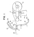
- FIG. 1 to 4 A first preferred embodiment of the present invention is illustrated in Figs. 1 to 4, in which reference numeral 11 designates a film, numerals 12 and 13 designate cores, and these cores 12 and 13 are pivotably supported from the opposite end portions of a turret 16 so as to be rotatable in the direction of arrow A as driven by a driving device not shown, the turret 16 being mounted on a frame 19 so as to be rotatable about its center in the direction of arrow C.
- arms 18 are provided on the opposite sides of the central portion of the turret 16 as projecting therefrom, and at the respective tip end portions of the arms 18 are pivotably supported guide rolls 17, respectively.
- Reference numeral 14 designates a mill roll formed by winding up the film 11 around the core 18.
- a guide roll 27 along a film feed passageway
- swingable arms 26 and 23 which can swing about the same axis D.
- the swingable arm 23 has electrostatic charging means 20 and a cutter 22 mounted at its tip end portion, and a press roll 25 is pivotably mounted at the tip end portion of the swingable arm 26.
- a similar swingable arm 24 having electrostatic charging means 20a mounted at its tip end portion is pivotably mounted on the same frame 28 under the above-described guide roll 27 so as to swing about point E.
- electrode sections of the well-known blast type electrostatic charging devices such as, for example, the heretofore commonly used devices in which ionized air produced by corona discharge between high-voltage electrodes is blasted by a blower or a compressor, are employed. It is to be noted that a power supply section and wirings of the electrostatic charging device are omitted from illustration.
- Fig. 1 shows the state of the apparatus at the time point when the mill roll 14 on the right-side core 12 as viewed in the figure has reached a full amount.
- the wound length of the film 11 is measured by a wound length counter not shown, and when it has reached the full amount, the arm 24 is actuated, and is made to stand by at the position shown in Fig. 2, subsequently the arms 23 and 26 are actuated to cut the film 11 by the cutter 22 and to simultaneously press the film 11 against the new core 13 by means of the press roll 25.
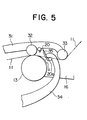
- a cutter 35 is mounted at a tip end of an arm 34 which corresponds to the arm 24 in the first preferred embodiment, further an upper swingable arm 31 is provided only one, a press roll 32 being pivotably supported at the middle of the arm 31, a guide roll 33 also being pivotably supported at the tip end portion of the arm 31, and electrostatic charging means 20 is mounted on the arm 31 close to the press roll 32 on the side of the guide roll 33.
- the construction is identical to the first preferred embodiment.
- the stop position of the cutter 35 can be made as close as possible to the core 13 for the purpose of minimizing the length of the film end portion a.
- the arm 31 is also lowered to the position shown in Fig. 5, to press the film 11 onto the cutter 35 at a high speed by the rolls 32 and 33, and thereby the film 11 can be cut.
- ionized air is blasted from the electrode sections 20 and 20a of the electrostatic charging means onto the cut end portion a of the film 11, thereby the charged cut end portion a of the film 11 is made to adhere to the core 13, and then winding of the film 11 around the core 13 is carried out.
- the arms 31 and 34 are respectively made to ascend and descend, respectively. It is to be noted that either the arm 31 could be made to descend first and subsequently the arm 34 could be made to ascend to cut the film 11 or the arms 31 and 34 could be actuated simultaneously.
- Fig. 6 shows still another preferred embodiment of the present invention. Differences between this preferred embodiment and the above-described embodiment illustrated in Fig. 5 exist in that the single arm.31 in Fig. 5 is modified into two arms 36 and 38, a guide roll 37 is mounted at the tip end of the arm 36, electrostatic charging means 20 is mounted at the tip end of the other arm 38, and a press roll 39 is pivotably supported from the same arm 38 close to the electrostatic charging means on its inner side. With regard to the remainder of the apparatus, the construction is identical to the preferred embodiment shown in Fig. 5.
- the arm 34 could be made to swing prior to the swing motions of the arms 36 and 38, or else, all the arms 34, 36 and 38 could be actuated simultaneously to cut the film 11.
- the press rolls 25, 32 and 39 can be used as a lay-on roll for controlling winding hardness of the mill roll.
- the cut end portion of the film could be made to adhere to the core only by giving electrostatic charge onto the cut end portion.
- the electrostatic charging device can be employed only one (for instance, the electrode section 20 only), or three or more.
- the cut end portion of the film could be wrapped around the core by separately performing electrostatic charging and air-blasting for pressing.
- an electrostatic charging electrode section could be provided at the mount position of the electrode section 20, and an air-blasting nozzle section could be provided at the mount position of the electrode section 20a.
- the film is made to adhere to the core by charging the film, in a tapeless winding system there is no need to embrace the core with the film prior to cutting, hence in the final portion of winding of a mill roll, a film section which comes into contact with the core and is subjected to scratching damage, resulting in loss of a yield, can be eliminated, and so, a yield of a film is greatly improved. It is to be noted that this effect becomes more remarkable as the winding speed of a film becomes faster.
Landscapes
- Replacement Of Web Rolls (AREA)
- Advancing Webs (AREA)
- Winding Of Webs (AREA)
- Folding Of Thin Sheet-Like Materials, Special Discharging Devices, And Others (AREA)
Abstract
Description
- The present invention relates to an automatic cutting and winding apparatus for a web-like material such as a film, which automatically cuts a web-like material such as a film and continuously performs rewinding, and which is applicable to a biaxial oriented film manufacturing system, an unoriented film manufacturing system or the like.
- A winding system for a web-like material such as a film (hereinafter called simply "film") in which a medium for giving an adhesiveness such as an adhesive tape is not used on a core but a film is wrapped directly around a core (hereinafter called "tapeless winding system") has been being given attention in various fields because damages of films in inner layers of a mill roll caused by unevenness of a core surface due to an adhesive tape or the like are not present and also a work of removing remaining adhesive materials upon reuse of the core is unnecessary, but there still remain problems such that scratches are generated at a cut end of a film, and therefore, development of a more complete system has been strongly desired.
- It is therefore one object of the present invention to provide a novel automatic cutting and winding apparatus for a web-like material such as a film in which an adhesive tape is not used on a core around which the web-like material is to be newly wound, but nevertheless upon making the web-like material embrace the core and cutting the web-like material, scratches are not generated at the cut end portion of the web-like material.
- According to one feature of the present invention, there is provided a turret type automatic cutting and winding apparatus for automatically cutting a web-like material by means of a press roll and a cutter and winding it around a core, which apparatus comprises electrostatic charging means mounted on a swingable arm or arms for giving electrostatic charge on a cut end portion of the web-like material.
- Since the turret type automatic cutting and winding apparatus according to the present invention is constructed in the above-featured manner, upon cutting a web-like material and rewinding it on a new core, the swingable arm or arms would make swing motion, electrostatic charge is given on a cut end portion of the web-like material by the electrostatic charging means mounted on the swingable arm or arms, thereby the cut end portion of the web-like material is made to adhere to the surface of the new core by an electrostatic attracting force, and simultaneously, winding of the web-like material around the new core is commenced. Therefore, slip would not occur between the surface of the new core and the cut end portion of the web-like material, and so, scratches would not be generated at the cut end portion of the web-like material.
- The above-mentioned and other objects, features and advantages of the present invention will become more apparent by reference to the following description of preferred embodiments of the invention taken in conjunction with the accompanying drawings.
- In the accompanying drawings:
- Fig. 1 is a schematic side view showing one preferred embodiment of the present invention in a state before cutting a film;
- Fig. 2 is a schematic side view showing the same preferred embodiment but in a different state just after cutting a film;
- Fig. 3 is an enlarged schematic side view showing an essential part of the embodiment in Fig. 2;
- Fig. 4 is a schematic side view showing the same preferred embodiment but in a further different state where a film is being continuously wound around a new core;
- Fig. 5 is an enlarged schematic side view showing an essential part of another preferred embodiment of the present invention in a state just after cutting a film;
- Fig. 6 is an enlarged schematic side view showing an essential part of still another preferred embodiment of the present invention in a state just after cutting a film;
- Fig. 7 is a schematic side view showing one example of a turret type automatic cutting and winding apparatus for a film in the prior art in a state where the film is being continuously wound around a last core;
- Fig. 8 is a schematic side view showing the same apparatus in the prior art but in a different state where the film is made to embrace a new core; and
- Fig. 9 is a schematic side view showing the same apparatus in the prior art but in a further different state just after cutting the film.
- Before entering the description of the preferred embodiments of the present invention, a construction and an operation of one example of a turret type automatic cutting and winding apparatus for a film will be described in greater detail with reference to Figs. 7 to 9. In these figures, reference numeral 1 designates a film,
reference numeral 2 designates a new core around which a cut film is to be rewound, and thiscore 2 is mounted on one arm of a turret 4 so as to be rotationally driven in the direction of arrow A by means of a driving device not shown. Reference numeral 3 designates a guide roll that is pivotably supported at an end of another arm of the turret 4 angularly apart by 90° from the arm on which thecore 2 is mounted.Reference numeral 5 also designates a guide roll, which is pivotably supported at a film feed end of aframe 10, and in addition, aswingable arm 7 pivotably supporting at its tip end awrapping roll 6, which can be revolved in the direction of arrow B so as to traverse a middle portion between theguide roll 5 and thecore 2, is pivotably supported at the other end by one end of theframe 10 on the side of winding the film. - The above-mentioned
wrapping roll 6 is adapted to revolve so as to traverse the middle portion between theguide roll 5 and thecore 2 as described above and to reach the rear side of thecore 2. Reference numeral 8 designates a cutter mounted at a tip end of an arm 9 which is likewise pivotably mounted at the other end to an appropriate position of theframe 10. This arm 9 is adapted to be made to swing in synchronism with the revolution of thewrapping roll 6 by a driving device not shown and to cut the film 1 with the cutter 8 mounted at its tip end. - Describing now the operation of the above-described apparatus, in Fig. 7, the film 1 is being continuously wound around a core (not shown) mounted at an remote end of the turret 4 on the opposite side to the end where the
core 2 is mounted. If a mill roll being wound around that core reaches its full volume, then thewrapping roll 6 advances in the direction of B so as to embrace thecore 2 with the film 1, and the state shown in Fig. 8 is attained. - Subsequently, the cutter 8 is made to descend to cut the film 1 as shown in Fig. 9, then a film end a is forced to enter a gap space b between the
core 2 and thewrapping roll 6, and thereby wrapping is finished. - However, in the case of the prior art apparatus as described above, in order to wrap in the cut end a of the film upon rewinding a cut film around a new core in the above-described manner, it is necessary to embrace the
core 2 with the film 1 prior to cutting as shown in Fig. 8, but the film 1 is held under a predetermined tension generated for winding between thewrapping roll 6 and the guide roll 3 in Fig. 7, and so, upon transferring from the state shown in Fig. 7 to the state shown in Fig. 8 it is necessary to gradually move theroll 6 during a plenty of time, for the purpose of preventing generation of breaking, zig-zag traveling, corrugation and the like due to an unnatural force applied to the film 1. - But since the surface of the
core 2 is not smooth as is the case with a smoothing roll, and since the circumferential speed of thecore 2 is preset somewhat faster than the traveling speed of the film 1 in order to prevent slackening of the film immediately after the wrapping, slip would occur between the film 1 and thecore 2, hence scratches are generated on the film 1, and so, the portion of the film scratched by thecore 2 is unacceptable as a product. This loss amount would become larger as the film traveling speed becomes higher. - Now the present invention will be described in more detail in connection to preferred embodiments of the invention with reference to Figs. 1 to 6.
- A first preferred embodiment of the present invention is illustrated in Figs. 1 to 4, in which reference numeral 11 designates a film,
numerals cores turret 16 so as to be rotatable in the direction of arrow A as driven by a driving device not shown, theturret 16 being mounted on aframe 19 so as to be rotatable about its center in the direction of arrow C. - In addition,
arms 18 are provided on the opposite sides of the central portion of theturret 16 as projecting therefrom, and at the respective tip end portions of thearms 18 are pivotably supportedguide rolls 17, respectively.Reference numeral 14 designates a mill roll formed by winding up the film 11 around thecore 18. - On the film feed side of the above-described
frame 19 is disposed anotherframe 28, is pivotably mounted aguide roll 27 along a film feed passageway, and also on theframe 19, adjacent to theguide roll 27 are pivotably mountedswingable arms swingable arm 23 has electrostatic charging means 20 and acutter 22 mounted at its tip end portion, and apress roll 25 is pivotably mounted at the tip end portion of theswingable arm 26. In addition, a similarswingable arm 24 having electrostatic charging means 20a mounted at its tip end portion is pivotably mounted on thesame frame 28 under the above-describedguide roll 27 so as to swing about point E. For the electrostatic charging means 20 and 20a, electrode sections of the well-known blast type electrostatic charging devices such as, for example, the heretofore commonly used devices in which ionized air produced by corona discharge between high-voltage electrodes is blasted by a blower or a compressor, are employed. It is to be noted that a power supply section and wirings of the electrostatic charging device are omitted from illustration. - Now description will be made on the operation in the case where tapeless winding of a film is carried out by making use of the apparatus according to the above-described embodiment of the present invention. Fig. 1 shows the state of the apparatus at the time point when the mill roll 14 on the right-
side core 12 as viewed in the figure has reached a full amount. The wound length of the film 11 is measured by a wound length counter not shown, and when it has reached the full amount, thearm 24 is actuated, and is made to stand by at the position shown in Fig. 2, subsequently thearms cutter 22 and to simultaneously press the film 11 against thenew core 13 by means of thepress roll 25. Furthermore, simultaneously with the cutting, ionized air is blasted from the blast type electrostatic charging means 20 and 20a towards the cut end portion a of the film 11 in the directions of arrows g and h, thus the cut end portion a of the film 11 is pressed against thecore 13 by the wind force as being charged, thereby winding of the film 11 is carried out with the cut end portion a of the film 11 adhering to thecore 13, and after all, automatic cutting and rewinding can be achieved in a tapeless system (Fig. 3). - Once wrapping of the cut end portion a of the tape 11 around the
new core 13 has been finished, thearms mew core 13, winding of the film 11 is carried out to form armill roll 15. It is to be noted that so long as it is possible to realize the state shown in Fig. 2 upon cutting the film 11, the sequence of actuations of therespective arms - Now description will be made on different preferred embodiments of the present invention, especially with respect to the points different from the above-described first preferred embodiment. Figs. 5 and 6, respectively, show different modified embodiments of the present invention.
- At first, describing about the preferred embodiment illustrated in Fig. 5, a
cutter 35 is mounted at a tip end of anarm 34 which corresponds to thearm 24 in the first preferred embodiment, further an upperswingable arm 31 is provided only one, apress roll 32 being pivotably supported at the middle of thearm 31, aguide roll 33 also being pivotably supported at the tip end portion of thearm 31, andelectrostatic charging means 20 is mounted on thearm 31 close to thepress roll 32 on the side of theguide roll 33. With regard to the remainder of the apparatus, the construction is identical to the first preferred embodiment. - By employing the above-described construction, when the
arm 34 has been made to swing to the position shown in Fig. 5, the stop position of thecutter 35 can be made as close as possible to thecore 13 for the purpose of minimizing the length of the film end portion a. Thereafter, thearm 31 is also lowered to the position shown in Fig. 5, to press the film 11 onto thecutter 35 at a high speed by therolls electrode sections core 13, and then winding of the film 11 around thecore 13 is carried out. - When the wrapping of the cut end portion a of the film 11 around the
core 13 has been finished, thearms arm 31 could be made to descend first and subsequently thearm 34 could be made to ascend to cut the film 11 or thearms - Fig. 6 shows still another preferred embodiment of the present invention. Differences between this preferred embodiment and the above-described embodiment illustrated in Fig. 5 exist in that the single arm.31 in Fig. 5 is modified into two
arms guide roll 37 is mounted at the tip end of thearm 36,electrostatic charging means 20 is mounted at the tip end of theother arm 38, and apress roll 39 is pivotably supported from thesame arm 38 close to the electrostatic charging means on its inner side. With regard to the remainder of the apparatus, the construction is identical to the preferred embodiment shown in Fig. 5. - Describing now the operation of the modified embodiment shown in Fig. 6, after the
arm 34 has been made to ascend to the position shown in Fig. 6, thearm 38 is made to descend to press theroll 39 against thecore 13, at the same time thearm 36 is made to descend to bring theguide roll 37 into contact with the film 11, and while a tension is being applied to the film 11 by thearm 36 and theguide roll 37, thecutter 35 is pressed against the film 11 to cut it. Similarly to the embodiment shown in Fig. 5, simultaneously with cutting of the film 11, ionized air is blasted from theelectrode sections core 13, and then winding of the film 11 around thecore 13 is carried out. In the above-mentioned operation, thearm 34 could be made to swing prior to the swing motions of thearms arms - In the above-described respective embodiments, the press rolls 25, 32 and 39 can be used as a lay-on roll for controlling winding hardness of the mill roll. Moreover, without employing the blasting of ionized air, the cut end portion of the film could be made to adhere to the core only by giving electrostatic charge onto the cut end portion. If necessary, the electrostatic charging device can be employed only one (for instance, the
electrode section 20 only), or three or more. Still further, the cut end portion of the film could be wrapped around the core by separately performing electrostatic charging and air-blasting for pressing. For instance, an electrostatic charging electrode section could be provided at the mount position of theelectrode section 20, and an air-blasting nozzle section could be provided at the mount position of theelectrode section 20a. - As described in detail above, according to the present invention, since simultaneously with cutting of a film, the cut end portion of the film is pressed against a core by air-blasting, the film is made to adhere to the core by charging the film, in a tapeless winding system there is no need to embrace the core with the film prior to cutting, hence in the final portion of winding of a mill roll, a film section which comes into contact with the core and is subjected to scratching damage, resulting in loss of a yield, can be eliminated, and so, a yield of a film is greatly improved. It is to be noted that this effect becomes more remarkable as the winding speed of a film becomes faster.
- Since many changes and modifications in design can be made to the above-described construction without departing from the spirit of the present invention, it is intended that all matter contained in the above description and illustrated in the accompanying drawings shall be interpreted to be illustrative and not in a limiting sense.
Claims (4)
Applications Claiming Priority (2)
| Application Number | Priority Date | Filing Date | Title |
|---|---|---|---|
| JP59253090A JPS61130164A (en) | 1984-11-30 | 1984-11-30 | Automatic cutting/winding device of band-like material such as film |
| JP253090/84 | 1984-11-30 |
Publications (3)
| Publication Number | Publication Date |
|---|---|
| EP0183135A1 true EP0183135A1 (en) | 1986-06-04 |
| EP0183135B1 EP0183135B1 (en) | 1988-05-18 |
| EP0183135B2 EP0183135B2 (en) | 1991-12-04 |
Family
ID=17246348
Family Applications (1)
| Application Number | Title | Priority Date | Filing Date |
|---|---|---|---|
| EP85114435A Expired - Lifetime EP0183135B2 (en) | 1984-11-30 | 1985-11-13 | Automatic cutting and winding apparatus for a web-like material such as a film |
Country Status (6)
| Country | Link |
|---|---|
| US (1) | US4678133A (en) |
| EP (1) | EP0183135B2 (en) |
| JP (1) | JPS61130164A (en) |
| KR (1) | KR890003939B1 (en) |
| CN (1) | CN1003440B (en) |
| DE (2) | DE183135T1 (en) |
Cited By (11)
| Publication number | Priority date | Publication date | Assignee | Title |
|---|---|---|---|---|
| EP0237903A1 (en) | 1986-03-17 | 1987-09-23 | Mitsubishi Jukogyo Kabushiki Kaisha | Automatic cutting and winding apparatus for a web-like material such as a film |
| EP0270498A1 (en) * | 1986-12-04 | 1988-06-08 | Gottlieb Looser | Winding method and apparatus |
| EP0255674A3 (en) * | 1986-08-06 | 1988-08-31 | Sundwiger Eisenhutte Maschinenfabrik Grah & Co | Apparatus for producing cast metal strip with an amorphous and/or fine crystal structure |
| WO1996023720A1 (en) * | 1995-01-30 | 1996-08-08 | Kampf Gmbh & Co. Maschinenfabrik | Device for applying a material strip to a winding tube |
| DE10202462A1 (en) * | 2001-10-24 | 2003-05-15 | Windmoeller & Hoelscher | Machine for forming reels of thermoplastic sheet has pressure roller, cutter blade and electrodes, electrodes and blade being attached to lever system connected to pressure roller mounting |
| DE10203149A1 (en) * | 2001-10-24 | 2003-05-22 | Windmoeller & Hoelscher | Mechanism for positioning pressure roller against winding drum comprises suspension arms connected by pivots to connector plates, one of which is piston-and-cylinder unit while other is mounted on spring |
| US7055776B2 (en) | 2001-10-24 | 2006-06-06 | Windmoeller And Hoelscher | Device for continuous winding of webs |
| EP2212228A1 (en) * | 2007-10-18 | 2010-08-04 | COLINES S.p.A. | Winding system for use in plastic films production lines, in particular extensible plastic films, and method for winding plastic film reels |
| WO2013156036A1 (en) * | 2012-04-18 | 2013-10-24 | Jesco Holding Aps | Winding apparatus for winding a web into a roll |
| EP3409818A1 (en) * | 2017-05-24 | 2018-12-05 | Trützschler GmbH & Co. KG | Cutting device for a nonwoven fabric winder and method for same |
| EP3536643A1 (en) * | 2018-03-09 | 2019-09-11 | Christa Dettke | Turret coiling machine with electrostatic fixing of the beginning of the web |
Families Citing this family (39)
| Publication number | Priority date | Publication date | Assignee | Title |
|---|---|---|---|---|
| JPH0688699B2 (en) * | 1986-07-23 | 1994-11-09 | 三菱重工業株式会社 | Automatic cutting and winding device for strips such as films |
| CH676113A5 (en) * | 1988-01-06 | 1990-12-14 | Electronova Sa | Storage-roll mechanism with automatic material starting |
| JPH0261858U (en) * | 1988-10-26 | 1990-05-09 | ||
| US5066352A (en) * | 1990-02-23 | 1991-11-19 | Cincinnati Milacron Inc. | Method and apparatus for forming composite pieces from composite sheet material |
| DE4115863A1 (en) * | 1991-05-15 | 1992-11-19 | Kampf Gmbh & Co Maschf | MULTIPLE-TURNING WRAPPING MACHINE FOR ROLLING GOODS, IN PARTICULAR FILMS OR THE LIKE |
| US5346150A (en) * | 1992-01-21 | 1994-09-13 | Minnesota Mining And Manufacturing Company | Tail gap winder |
| US5379962A (en) * | 1992-01-21 | 1995-01-10 | Minnesota Mining And Manufacturing Company | Heated web knife |
| US5632849A (en) * | 1992-01-21 | 1997-05-27 | Minnesota Mining And Manufacturing And Company | Tab applicator for log roll winders |
| US5383622A (en) * | 1993-05-05 | 1995-01-24 | The Kohler Coating Machinery Corporation | Web transfer mechanism and method for a continuous winder |
| US5464166A (en) * | 1994-08-26 | 1995-11-07 | E. I. Du Pont De Nemours And Company | Method and apparatus for automatic roll transfer |
| CN1264325A (en) * | 1997-07-15 | 2000-08-23 | 丹尼利机械设备股份公司 | Coiling machine for hot rolled stock such as strip or sheet and relative coiling method |
| US5845867A (en) * | 1997-10-10 | 1998-12-08 | The Black Clawson Company | Continuous winder |
| US6145777A (en) * | 1999-04-28 | 2000-11-14 | 3M Innovative Properties Company | Single station continuous log roll winder |
| DE10116973B4 (en) | 2001-04-05 | 2005-11-17 | Reifenhäuser GmbH & Co Maschinenfabrik | winding device |
| EP1433730B1 (en) | 2002-10-25 | 2007-01-10 | Reifenhäuser GmbH & Co. Maschinenfabrik | Winding device and method for performing a winding tube change in a winding device |
| ES2274150T3 (en) * | 2003-08-07 | 2007-05-16 | REIFENHAUSER GMBH & CO. MASCHINENFABRIK | CROSS CUTTING DEVICE FOR A BAND OF MATERIAL. |
| ITFI20030302A1 (en) * | 2003-12-01 | 2005-06-02 | Faper S R L Ora Focus Srl | AUTOMATIC GRIPPING DEVICE FOR THE COIL CHANGE |
| DE102004049329A1 (en) * | 2004-10-09 | 2006-04-20 | Windmöller & Hölscher Kg | Apparatus and method for transporting webs of material and fixing them on a counter-surface |
| EP2039635A1 (en) * | 2007-09-22 | 2009-03-25 | Reifenhäuser GmbH & Co. KG Maschinenfabrik | Device for traverse separation and initial winding of a fed material sheet, in particular a plastic sheet film |
| CN101970321B (en) * | 2007-10-16 | 2014-04-09 | 格罗特斯工程公司 | Stretch film winder |
| US20100320302A1 (en) * | 2009-06-23 | 2010-12-23 | Catbridge Machinery, Llc | In-Line Formed Core Supporting a Wound Web |
| JP6030909B2 (en) * | 2012-10-02 | 2016-11-24 | リンテック株式会社 | Sheet sticking device and sheet sticking method |
| JP6069020B2 (en) * | 2013-02-20 | 2017-01-25 | リンテック株式会社 | Sheet sticking device and sticking method |
| US20140263805A1 (en) * | 2013-03-15 | 2014-09-18 | Davis-Standard, Llc | Winding apparatus with a support arm |
| CN103303719A (en) * | 2013-05-31 | 2013-09-18 | 泰兴联创绝缘材料有限公司 | Winding, cutting and beginning device for coating machine |
| JP6019061B2 (en) * | 2014-06-17 | 2016-11-02 | 株式会社不二鉄工所 | Sheet winding device |
| CN104150258A (en) * | 2014-07-11 | 2014-11-19 | 佛山市宝索机械制造有限公司 | Rewinder with quick paper breaking function |
| CN104477684A (en) * | 2014-12-19 | 2015-04-01 | 松德机械股份有限公司 | Film cutting-off device |
| DE102015114391B4 (en) * | 2015-08-28 | 2020-05-20 | Windmöller & Hölscher Kg | Receiving means for receiving film material |
| CN105692287A (en) * | 2016-04-27 | 2016-06-22 | 昆山巨闳机械科技有限公司 | Direct leather cutting device |
| ITUA20163344A1 (en) * | 2016-05-11 | 2017-11-11 | Celli Nonwovens Spa | MACHINE AND METHOD FOR THE WINDING OF STRIPS OF MATTRESS WITH THE MEANS OF TRANSVERSAL CUTTING OF THE STRIPS AND ANCHORING OF THE STRIPES AT THE ANCHORING SOUL |
| CN107010446B (en) * | 2017-05-25 | 2018-08-28 | 浙江明佳环保科技有限公司 | A kind of printed film production coil handling apparatus |
| CN106986212B (en) * | 2017-05-25 | 2018-08-24 | 浙江明佳环保科技有限公司 | A kind of printed film production wrap-up convenient for change of lap |
| US11110645B2 (en) * | 2017-11-16 | 2021-09-07 | Rlmb Group, Llc | Method and systems for applying stretch films/plastic films at a controlled temperature |
| CN112478874B (en) * | 2020-12-09 | 2022-08-02 | 湖北北新建材有限公司 | Packing belt subpackaging device and subpackaging method |
| CN114212584A (en) * | 2021-12-02 | 2022-03-22 | 中材锂膜有限公司 | Wet process lithium battery diaphragm automatic winding and rewinding system |
| CN115027993A (en) * | 2022-05-16 | 2022-09-09 | 晟通科技集团有限公司 | Rewinding equipment |
| KR102529234B1 (en) * | 2022-08-12 | 2023-05-04 | 주식회사 오피오 | Apparatus for foreign material remove of film paper |
| EP4653361A1 (en) * | 2024-05-20 | 2025-11-26 | Cason Companies Engineering S.r.l. | Device for automatic cutting and drawing-in onto tubular cores flexible materials wound on reels without the use of double-sided adhesive tape; in double-turret slitter rewinders |
Citations (2)
| Publication number | Priority date | Publication date | Assignee | Title |
|---|---|---|---|---|
| US3612270A (en) * | 1969-06-16 | 1971-10-12 | Clark Aiken Co | Cutter piler with electrostatic layboy |
| DE2301193A1 (en) * | 1973-01-11 | 1974-07-18 | Weser Lenze Stahlkontor | DEVICE FOR ROLL CHANGING AND CROSS-CUTTING OF HIGH-SPEED WEB IN MULTIPLE WRAPPING MACHINES |
Family Cites Families (6)
| Publication number | Priority date | Publication date | Assignee | Title |
|---|---|---|---|---|
| US2256082A (en) * | 1940-02-12 | 1941-09-16 | Cons Cover Co | Paper converting machine |
| US2769600A (en) * | 1952-07-16 | 1956-11-06 | Paper Converting Machine Co | Web winding machine |
| JPS5134545A (en) * | 1974-09-14 | 1976-03-24 | Koshihara Tetsukosho Kk | MADOTSUKI JOGEKAI HEITOBIRASOCHI |
| US3942735A (en) * | 1974-12-26 | 1976-03-09 | Levi Strauss & Co. | Viewing table |
| US4458852A (en) * | 1981-06-05 | 1984-07-10 | American Hoechst Corporation | Web transfer apparatus |
| IT1167967B (en) * | 1981-08-26 | 1987-05-20 | Fabio Perini | HIGH SPEED REWINDER FOR PAPER TAPES IN SPECIES WITH CROSS PERFORATIONS |
-
1984
- 1984-11-30 JP JP59253090A patent/JPS61130164A/en active Pending
-
1985
- 1985-10-28 KR KR1019850007958A patent/KR890003939B1/en not_active Expired
- 1985-11-13 DE DE198585114435T patent/DE183135T1/en active Pending
- 1985-11-13 DE DE8585114435T patent/DE3562754D1/en not_active Expired
- 1985-11-13 EP EP85114435A patent/EP0183135B2/en not_active Expired - Lifetime
- 1985-11-19 US US06/799,736 patent/US4678133A/en not_active Expired - Lifetime
- 1985-11-20 CN CN85108488.5A patent/CN1003440B/en not_active Expired
Patent Citations (2)
| Publication number | Priority date | Publication date | Assignee | Title |
|---|---|---|---|---|
| US3612270A (en) * | 1969-06-16 | 1971-10-12 | Clark Aiken Co | Cutter piler with electrostatic layboy |
| DE2301193A1 (en) * | 1973-01-11 | 1974-07-18 | Weser Lenze Stahlkontor | DEVICE FOR ROLL CHANGING AND CROSS-CUTTING OF HIGH-SPEED WEB IN MULTIPLE WRAPPING MACHINES |
Cited By (14)
| Publication number | Priority date | Publication date | Assignee | Title |
|---|---|---|---|---|
| EP0237903A1 (en) | 1986-03-17 | 1987-09-23 | Mitsubishi Jukogyo Kabushiki Kaisha | Automatic cutting and winding apparatus for a web-like material such as a film |
| EP0255674A3 (en) * | 1986-08-06 | 1988-08-31 | Sundwiger Eisenhutte Maschinenfabrik Grah & Co | Apparatus for producing cast metal strip with an amorphous and/or fine crystal structure |
| EP0270498A1 (en) * | 1986-12-04 | 1988-06-08 | Gottlieb Looser | Winding method and apparatus |
| WO1996023720A1 (en) * | 1995-01-30 | 1996-08-08 | Kampf Gmbh & Co. Maschinenfabrik | Device for applying a material strip to a winding tube |
| DE10202462B4 (en) * | 2001-10-24 | 2005-11-24 | Windmöller & Hölscher Kg | Machine for forming reels of thermoplastic sheet has pressure roller, cutter blade and electrodes, electrodes and blade being attached to lever system connected to pressure roller mounting |
| DE10203149A1 (en) * | 2001-10-24 | 2003-05-22 | Windmoeller & Hoelscher | Mechanism for positioning pressure roller against winding drum comprises suspension arms connected by pivots to connector plates, one of which is piston-and-cylinder unit while other is mounted on spring |
| DE10202462A1 (en) * | 2001-10-24 | 2003-05-15 | Windmoeller & Hoelscher | Machine for forming reels of thermoplastic sheet has pressure roller, cutter blade and electrodes, electrodes and blade being attached to lever system connected to pressure roller mounting |
| DE10203149B4 (en) * | 2001-10-24 | 2005-12-08 | Windmöller & Hölscher Kg | Mechanism for positioning pressure roller against winding drum comprises suspension arms connected by pivots to connector plates, one of which is piston-and-cylinder unit while other is mounted on spring |
| US7055776B2 (en) | 2001-10-24 | 2006-06-06 | Windmoeller And Hoelscher | Device for continuous winding of webs |
| EP2212228A1 (en) * | 2007-10-18 | 2010-08-04 | COLINES S.p.A. | Winding system for use in plastic films production lines, in particular extensible plastic films, and method for winding plastic film reels |
| WO2013156036A1 (en) * | 2012-04-18 | 2013-10-24 | Jesco Holding Aps | Winding apparatus for winding a web into a roll |
| US9555993B2 (en) | 2012-04-18 | 2017-01-31 | Jesco Holding A/S | Winding apparatus for winding a web into a roll |
| EP3409818A1 (en) * | 2017-05-24 | 2018-12-05 | Trützschler GmbH & Co. KG | Cutting device for a nonwoven fabric winder and method for same |
| EP3536643A1 (en) * | 2018-03-09 | 2019-09-11 | Christa Dettke | Turret coiling machine with electrostatic fixing of the beginning of the web |
Also Published As
| Publication number | Publication date |
|---|---|
| CN1003440B (en) | 1989-03-01 |
| US4678133A (en) | 1987-07-07 |
| EP0183135B2 (en) | 1991-12-04 |
| KR890003939B1 (en) | 1989-10-13 |
| DE183135T1 (en) | 1986-09-25 |
| KR860003895A (en) | 1986-06-13 |
| CN85108488A (en) | 1986-05-10 |
| JPS61130164A (en) | 1986-06-18 |
| EP0183135B1 (en) | 1988-05-18 |
| DE3562754D1 (en) | 1988-06-23 |
Similar Documents
| Publication | Publication Date | Title |
|---|---|---|
| EP0183135B1 (en) | Automatic cutting and winding apparatus for a web-like material such as a film | |
| US4541583A (en) | Continuous layon roller film winder | |
| US4770358A (en) | Automatic cutting and winding apparatus for a web-like material such as a film | |
| US5368253A (en) | Continuous rewind with no-fold-back splicer | |
| US3383062A (en) | Method and apparatus for continuously winding web material with constant tension | |
| EP0336911A3 (en) | Apparatus with a rotating device for gluing the end portion of material wound onto reels | |
| EP1007460A1 (en) | No-fold-back splicer with electrostatic web transfer device | |
| CN113955548A (en) | Adhesive tape-free reel changing device and reel changing method | |
| JP2005096915A (en) | Apparatus and method for taking up film | |
| CN101665194A (en) | Winding method for polymer films and apparatus thereof | |
| US6264130B1 (en) | Duplex web roll winding and splicing apparatus | |
| JP2538900B2 (en) | Cutting and winding device for strips | |
| JP2004035215A (en) | Pressure-sensitive adhesive tape coreless rolled material | |
| JPH0671958B2 (en) | Automatic cutting and winding device for strips such as films | |
| JPS62215452A (en) | Automatic cutting and winding device for strip material such as film | |
| JP2889986B2 (en) | Magnetic recording medium winding method | |
| JPH0626510Y2 (en) | Automatic cutting and winding device for strips such as films | |
| JP2554242B2 (en) | Automatic cutting and winding device for strips such as films | |
| JPH0688699B2 (en) | Automatic cutting and winding device for strips such as films | |
| JPS61119555A (en) | Butt-joint apparatus for webs | |
| JPS62285856A (en) | Automatic cutting winding device of web such as film | |
| JPH01231744A (en) | Film or sheet cutting/winding method and device | |
| JPH0138113Y2 (en) | ||
| JPH0613384B2 (en) | Automatic cutting and winding device for strips such as films | |
| JPS58183553A (en) | Method of and device for winding web |
Legal Events
| Date | Code | Title | Description |
|---|---|---|---|
| PUAI | Public reference made under article 153(3) epc to a published international application that has entered the european phase |
Free format text: ORIGINAL CODE: 0009012 |
|
| 17P | Request for examination filed |
Effective date: 19851210 |
|
| AK | Designated contracting states |
Kind code of ref document: A1 Designated state(s): DE FR GB |
|
| RIN1 | Information on inventor provided before grant (corrected) |
Inventor name: SUZUKI, TSUTOMU NAGOYA MACHINERY WORKS OF |
|
| EL | Fr: translation of claims filed | ||
| DET | De: translation of patent claims | ||
| 17Q | First examination report despatched |
Effective date: 19871014 |
|
| GRAA | (expected) grant |
Free format text: ORIGINAL CODE: 0009210 |
|
| AK | Designated contracting states |
Kind code of ref document: B1 Designated state(s): DE FR GB |
|
| REF | Corresponds to: |
Ref document number: 3562754 Country of ref document: DE Date of ref document: 19880623 |
|
| ET | Fr: translation filed | ||
| PLBI | Opposition filed |
Free format text: ORIGINAL CODE: 0009260 |
|
| 26 | Opposition filed |
Opponent name: LOOSER, GOTTLIEB Effective date: 19890206 |
|
| PUAH | Patent maintained in amended form |
Free format text: ORIGINAL CODE: 0009272 |
|
| STAA | Information on the status of an ep patent application or granted ep patent |
Free format text: STATUS: PATENT MAINTAINED AS AMENDED |
|
| 27A | Patent maintained in amended form |
Effective date: 19911204 |
|
| AK | Designated contracting states |
Kind code of ref document: B2 Designated state(s): DE FR GB |
|
| ET3 | Fr: translation filed ** decision concerning opposition | ||
| REG | Reference to a national code |
Ref country code: GB Ref legal event code: IF02 |
|
| PGFP | Annual fee paid to national office [announced via postgrant information from national office to epo] |
Ref country code: FR Payment date: 20041109 Year of fee payment: 20 |
|
| PGFP | Annual fee paid to national office [announced via postgrant information from national office to epo] |
Ref country code: GB Payment date: 20041110 Year of fee payment: 20 |
|
| PGFP | Annual fee paid to national office [announced via postgrant information from national office to epo] |
Ref country code: DE Payment date: 20041111 Year of fee payment: 20 |
|
| PG25 | Lapsed in a contracting state [announced via postgrant information from national office to epo] |
Ref country code: GB Free format text: LAPSE BECAUSE OF EXPIRATION OF PROTECTION Effective date: 20051112 |
|
| REG | Reference to a national code |
Ref country code: GB Ref legal event code: PE20 |