EP0188576B1 - Umlaufender rüttler - Google Patents
Umlaufender rüttler Download PDFInfo
- Publication number
- EP0188576B1 EP0188576B1 EP85903766A EP85903766A EP0188576B1 EP 0188576 B1 EP0188576 B1 EP 0188576B1 EP 85903766 A EP85903766 A EP 85903766A EP 85903766 A EP85903766 A EP 85903766A EP 0188576 B1 EP0188576 B1 EP 0188576B1
- Authority
- EP
- European Patent Office
- Prior art keywords
- tray
- accordance
- speed
- frame
- routine
- Prior art date
- Legal status (The legal status is an assumption and is not a legal conclusion. Google has not performed a legal analysis and makes no representation as to the accuracy of the status listed.)
- Expired
Links
- 230000033001 locomotion Effects 0.000 claims abstract description 51
- 239000000725 suspension Substances 0.000 claims abstract description 14
- 125000004122 cyclic group Chemical group 0.000 claims abstract description 8
- 239000011324 bead Substances 0.000 claims description 12
- 239000000463 material Substances 0.000 claims description 8
- 229920003023 plastic Polymers 0.000 claims description 3
- 239000004033 plastic Substances 0.000 claims description 3
- 230000008093 supporting effect Effects 0.000 claims description 3
- 238000012360 testing method Methods 0.000 description 15
- 230000006870 function Effects 0.000 description 12
- 238000013019 agitation Methods 0.000 description 11
- 238000003556 assay Methods 0.000 description 8
- 238000010586 diagram Methods 0.000 description 7
- 238000000034 method Methods 0.000 description 6
- 230000004044 response Effects 0.000 description 5
- 238000012546 transfer Methods 0.000 description 5
- 230000001133 acceleration Effects 0.000 description 4
- 210000001072 colon Anatomy 0.000 description 3
- 238000005452 bending Methods 0.000 description 2
- 239000003990 capacitor Substances 0.000 description 2
- 230000008859 change Effects 0.000 description 2
- 230000008878 coupling Effects 0.000 description 2
- 238000010168 coupling process Methods 0.000 description 2
- 238000005859 coupling reaction Methods 0.000 description 2
- 238000001125 extrusion Methods 0.000 description 2
- 238000002156 mixing Methods 0.000 description 2
- 230000008569 process Effects 0.000 description 2
- DHKHKXVYLBGOIT-UHFFFAOYSA-N 1,1-Diethoxyethane Chemical compound CCOC(C)OCC DHKHKXVYLBGOIT-UHFFFAOYSA-N 0.000 description 1
- 230000009471 action Effects 0.000 description 1
- XAGFODPZIPBFFR-UHFFFAOYSA-N aluminium Chemical compound [Al] XAGFODPZIPBFFR-UHFFFAOYSA-N 0.000 description 1
- 229910052782 aluminium Inorganic materials 0.000 description 1
- 238000013459 approach Methods 0.000 description 1
- 230000008901 benefit Effects 0.000 description 1
- 238000004166 bioassay Methods 0.000 description 1
- 239000002131 composite material Substances 0.000 description 1
- 150000001875 compounds Chemical class 0.000 description 1
- 230000001419 dependent effect Effects 0.000 description 1
- 230000000694 effects Effects 0.000 description 1
- 230000008030 elimination Effects 0.000 description 1
- 238000003379 elimination reaction Methods 0.000 description 1
- 238000002474 experimental method Methods 0.000 description 1
- 229920002457 flexible plastic Polymers 0.000 description 1
- 230000001976 improved effect Effects 0.000 description 1
- 230000001939 inductive effect Effects 0.000 description 1
- 230000000977 initiatory effect Effects 0.000 description 1
- 238000002347 injection Methods 0.000 description 1
- 239000007924 injection Substances 0.000 description 1
- 230000005923 long-lasting effect Effects 0.000 description 1
- 239000000203 mixture Substances 0.000 description 1
- 238000012986 modification Methods 0.000 description 1
- 230000004048 modification Effects 0.000 description 1
- 238000012545 processing Methods 0.000 description 1
- 230000005855 radiation Effects 0.000 description 1
- 230000007704 transition Effects 0.000 description 1
Images


Classifications
-
- G—PHYSICS
- G01—MEASURING; TESTING
- G01P—MEASURING LINEAR OR ANGULAR SPEED, ACCELERATION, DECELERATION, OR SHOCK; INDICATING PRESENCE, ABSENCE, OR DIRECTION, OF MOVEMENT
- G01P3/00—Measuring linear or angular speed; Measuring differences of linear or angular speeds
- G01P3/42—Devices characterised by the use of electric or magnetic means
- G01P3/44—Devices characterised by the use of electric or magnetic means for measuring angular speed
- G01P3/48—Devices characterised by the use of electric or magnetic means for measuring angular speed by measuring frequency of generated current or voltage
- G01P3/481—Devices characterised by the use of electric or magnetic means for measuring angular speed by measuring frequency of generated current or voltage of pulse signals
- G01P3/489—Digital circuits therefor
-
- B—PERFORMING OPERATIONS; TRANSPORTING
- B01—PHYSICAL OR CHEMICAL PROCESSES OR APPARATUS IN GENERAL
- B01F—MIXING, e.g. DISSOLVING, EMULSIFYING OR DISPERSING
- B01F31/00—Mixers with shaking, oscillating, or vibrating mechanisms
- B01F31/20—Mixing the contents of independent containers, e.g. test tubes
- B01F31/22—Mixing the contents of independent containers, e.g. test tubes with supporting means moving in a horizontal plane, e.g. describing an orbital path for moving the containers about an axis which intersects the receptacle axis at an angle
-
- B—PERFORMING OPERATIONS; TRANSPORTING
- B01—PHYSICAL OR CHEMICAL PROCESSES OR APPARATUS IN GENERAL
- B01F—MIXING, e.g. DISSOLVING, EMULSIFYING OR DISPERSING
- B01F35/00—Accessories for mixers; Auxiliary operations or auxiliary devices; Parts or details of general application
- B01F35/20—Measuring; Control or regulation
- B01F35/21—Measuring
- B01F35/212—Measuring of the driving system data, e.g. torque, speed or power data
-
- H—ELECTRICITY
- H02—GENERATION; CONVERSION OR DISTRIBUTION OF ELECTRIC POWER
- H02P—CONTROL OR REGULATION OF ELECTRIC MOTORS, ELECTRIC GENERATORS OR DYNAMO-ELECTRIC CONVERTERS; CONTROLLING TRANSFORMERS, REACTORS OR CHOKE COILS
- H02P23/00—Arrangements or methods for the control of AC motors characterised by a control method other than vector control
- H02P23/0077—Characterised by the use of a particular software algorithm
Definitions
- the present invention pertains generally to an agitation apparatus and is more specifically directed to such agitation apparatus that are used in a laboratory environment to agitate an assay with a generally orbital motion.
- the invention provides an improved orbital shaker apparatus which is quite in operation, and reliably produces an orbital or cyclic motion at a set speed and for a predetermined amount of time.
- the apparatus comprises a movable tray for supporting articles which are to be agitated such as clinical assays in beakers, flasks, test tubes or the like.
- the tray is supported by a suspension system which provides support for the loading of the tray with an assay while permitting a cyclic movement in the plane of the tray without undue resistance.
- the suspension system constrains the tray to move in translational modes only so that there is no rotation of the plane of the tray and every point on the tray subscribes substantially the same path.
- the translational constraints are provided by a suspension system which suspends the tray from a frame with flexible supports.
- the flexible supports are constrained so as to be flexible only in one dimension, and permit movement of the tray only along one axis with respect to the frame.
- the frame is suspended by flexible supports from a plurality of stationary stands so that it is constrained to translational movement along an axis perpendicular to the tray movement axis.
- the combination of the translational movements of the tray and the frame allow the tray to be moved in any number of precise cyclic motions. Because all the movement is produced by the bending of the flexible supports, there are no mechanical surfaces to rub together to create noise, friction, or tolerance errors.
- the orbital shaker 10 comprises a base 12 providing operator inputs including control keys 16-22 and keypad 24.
- a display means comprising a time display 26 and a speed display 28 are provided.
- the orbital shaker 10 imparts an exact orbital motion to specimens placed on a tray 14 which is moved in a prescribed cyclic motion at a particular speed and for a predetermined amount of time.
- One important object of the invention is to impart the same motion at each of the corners 30, 34, 36 and 38, of the tray 14 as that imparted in the middle 32 of the tray 14. This is accomlished by preventing the plane of the tray 14 from rotating and containing it to move in its translational modes. In this manner, uniformity agitation for the many assays contained on the tray will be assured.
- the motion which will be described with respect to the preferred embodiment will be an orbital motion of a circular nature.
- orbital motions which are not circular, such as elliptical, oval or the like, or even more compound shapes are within the scope of the invention.
- single axis or plural axis translational movements are available from the apparatus and depend only upon the driving means. All these motions can be produced by the apparatus with precision and without noise as will be more fully explained hereinafter.
- the operator control keys comprise the four pushbutton switches, 16, 18, 20, and 22.
- the pushbutton 18 is the start button and, assuming all conditions are clear for initiating motion of the tray 14, pressing this button will initiate the agitation operation.
- the stop button, control key 16 will cause a termination of the motion of the tray 14 prior to a timeout.
- the operator controls are used to produce input signals which will cause the apparatus to cyclicly move the tray at a set velocity for a predetermined period of time.
- the velocity which the operator wishes to produce for the motion is input by pressing the change-speed key 22 and then entering a three digit numerical value with the 0-9 keys of keyboard 24. This velocity set point is then displayed in the digits of the speed display 28.
- the time period for the agitation at the constant velocity is input to the apparatus by pressing the change-time button 20 and then entering a numerical value from the keyboard 24. This time period is entered into the time display 26 and indicates the amount of time the material in the tray should be agitated for a particular experiment.
- Pressing the change-speed key while simultaneously holding in the 1 or 2 key causes the speed of the apparatus to ramp up or ramp down, respectively, while the apparatus is running.
- Pressing the change-time key while simultaneously holding in the 1 or 2 key causes the time display 26 to be set for hours and minutes in the first instance and minutes and seconds in the second.
- the motion of the tray 14 is produced by a direct drive, including a DC motor 37 having a drive shaft 31 substantially perpendicular to the plane of the tray 14.
- the drive shaft 31 fits into a bore of a counterweight 39 which has an offset or eccentric drive pin 34 substantially parallel to the drive shaft 31.
- Rotation of the drive shaft 31 by the motor produces an orbit (in the embodiment circular) of the drive pin 35 about the motor.
- the drive pin 35 is coupled through a support plate 15 by means of a bushing 33 on the tray 14. This direct drive orbiting of the vertically oriented axis of the motor and the counterweight produce a smooth continuous orbital motion for the tray 14.
- the counterweight 39 is generally about one-half of the maximum load that the tray 14 is designed to hold and thus will substantially balance many loads.
- the counterweight 39 helps center the rotational mass over the motor axis.
- the counterweight 39 is to overcome the inertia of the load placed on the tray, but does not have to overcome the acutal weight of the load because the tray 14 is supported by the backing plate 15 which is mounted on suspension means which bear the weight of the load.
- the direct drive motor 37 can be controlled with a closed loop feedback control to produce a precise speed of rotation.
- a large slotted disc 40 is mounted between the counterweight 39 and the motor 37 and spins with the rotation of the orbit.
- An optoelectric slot sensor 46 is clamped over the slotted edge portions of the disc 40 and produces a signal for every passage of slots 42, 44.
- the optoelectric sensor 46 is mounted on a strip mount 52 which is fixed to a U-shaped support bracket 50, connected between two stationary support stands 54 and 56.
- the support for the weight of the tray is provided by a generally rectangular frame which is supported at its corners by support stands 54, 56, 58, and 60, which are fixedly secured to the base 12.
- the frame comprises four generally channel shaped elements 61, 62, 74 and 78 assembled in a rectangular box around the support stands 54, 56, 58 and 60.
- the backing plate 15 is suspended on this frame by means of four flexible connections which couple the frame to a backing-plate hanger 72 and backing plate hanger 80 extending substantially parallel and longitudinally across opposite ends of the backing-plate 15.
- the hangers 72, 80 are additionally generally channel shaped in cross section and include a mounting means 71 with a slot opening to a narrow neck which is adapted to retain a bead. Coupling the backing-plate supports 74 and 78 to the backing-plate hangers 72 and 80 are flexible links 68 and 70, respectively.
- the flexible link 84 illustrated in FIGURE 6, is relatively rectangular with generally circular beads 86 and 88 on each end.
- the beads 86,88 taper into a slimmer flexible portion which connects the two ends of a link.
- the beads can be slid into the mounting members, for example 71 and 73, to provide a connection to the hangers.
- the opposite bead can be slid into identical mounting means in the supports 74, 76 to provide an interlocking of the flexible members 68, 70 therein.
- Projections 85,87 and 89 can be provided on the link 84 to ensure an interference fit in the mounting slots so the ends of the links do not move. It is seen, therefore, that the support plate 15 and thus, the tray 14, is constrained to move only in the Y direction, as pictured in FIGURE 4, with respect to the support frame.
- the support frame is suspended from the anchored stands 54, 56, 58 and 60.
- the stands 56 and 58 provide support for hanger elements 61 and 62, respectively.
- the coupling between the stands and the hanger elements is provided by flexible links 64 and 66 similarly constructed to that previously described for the flexible link 84 shown in FIGURE 6.
- the beads of the flexible links slide into the mounting means of the stands and hangers to provide fixed end points between which the links can flex. Therefore, the inner frame is constrained to move in only one direction, referenced as X in FIGURE 3.
- the stands 54, 56, 58 and 60; the frame members 61, 62, 74 and 78; and the backing-plate hangers 72 and 80 are all of similar cross-section.
- an aluminum extrusion process is used for forming the cross section and the various widths for the channel shaped members are all cut from a run of the extrusion.
- the cross section illustrated for each element, for example, hanger 80 has a laterally extending foot 81 and a laterally extending arm 83. On the end of each arm is the slot used for gripping the beads of a flexible link.
- adjacent channel members 78, 80 which are connected by a flexible link 70 are inverted to each other such that the arms oppose each other and the slots line up.
- various channels such as those shown at 73,75 and 77 may be formed in the cross sections of the channel shaped members to provide anchors for the screws, for example, 91, 93, which hold the pieces of the frame together.
- FIGURE 5 A composite view of one corner of the suspension system of the tray 14 is illustrated in FIGURE 5.
- the corner that was chosen is the stand referenced 58 but the other corners which have stands 54, 56 and 60 are similarly constructed. It is evident that the frame is constrained to move only in the X direction while the backing plate 15 is constrained to move only in the other direction Y. However, the constraint of movement of the backing plate in the Y direction is relative to the movement of the frame which has X motion. Therefore, force on of the backing plate caused by the orbital motion of the drive pin 35 causes movement not only of the backing plate 15 but also of the frame and, in a combination of the two translational motions, a smooth circular motion for the tray 14.
- the links are preferably comprised of a flexible plastic material for example, that manufactured by the DuPont Corp. under the trademark DELRIN 500. It is noted that the link is thicker at the bead and tapers to a thinner central portion that connects the two beads. This provides for uniform flexibility along the length of the link. The substantial width of each link helps resist torsional or twisting force components and maintains the one dimensional movement constraint for each link. This material can be injection molded from a lateral edge so that the molecules of the material line up along the lines of flexure. This produces a link which is capable of bending without failure for an extended lifetime.
- DELRIN 500 a flexible plastic material for example, that manufactured by the DuPont Corp. under the trademark DELRIN 500. It is noted that the link is thicker at the bead and tapers to a thinner central portion that connects the two beads. This provides for uniform flexibility along the length of the link. The substantial width of each link helps resist torsional or twisting force components and maintains the one dimensional movement constraint for each
- the material is advantageously used in this particular instance because it will not stretch under the tension of the loading designed for the tray 14 and importantly does not make any noise during movement while flexing. A very quite, long lasting suspension link is thereby provided. It should be evident, however, that other materials can be used, both plastics and non-plastics, for the links which suspend the tray. Further, links which pivot about the suspension points can be used but are not as judicious as the present implementation where the links flex along their length because of a lack of wear and noiseless movement.
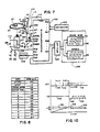
- FIG. 7 there is shown an electronic schematic diagram illustrating a microprocessor based controller for the orbital shaker apparatus.
- a microprocessor 100 receives the keyboard inputs via its port A lines PAO-PA7. The operator by pressing keys on the keyboard 102 thereby inputs commands and information for the different functions of the system.
- the microprocessor through port B lines, PBO-PB7, and a port C line, PC3, communicates with the display means 106 via a driver circuit 104.
- the driver circuit 104 controls the specific elements of the seven segment displays which are lit up relative to the data that is transmitted.
- the driver circuit 104 controls both the time display 26 and the speed display 28.
- the display means 106 will now be more fully explained with reference to FIGURE 11, which shows a detailed electric schematic of the device. It is seen that the display comprises a first display driver 200 and a second display driver 228.
- the two drivers are connected to four display modules 204, 206, 208 and 210 each containing two, seven segment, LED digits.
- the display driver 200 has inputs A-D which connect to port B lines, PBO-PB3, and are decoded into outputs QO-Q6. These outputs form the signals over a common bus 202 to the inputs L1 ⁇ L7 of the display modules 204, 206, 208 and 210.
- the decoded signals on the common bus 202 indicate which segments in the display digit is to be visible.
- the display driver 228 is similar to that described for display driver 200 and includes inputs A-D connected port B lines, PB4-PB7. The digital input from these lines is decoded into outputs QO-Q7 which are then transmitted to the bases of transistors 212-226, respectively.
- Each transistor 212-226 is an NPN transistor with its collector connected to an enable input of a display module and its emitter connected to ground.
- Each display module has two such enable inputs EN1, EN2 for selecting the particular digit that the line inputs L1 ⁇ L7 will energize. For example, a high level output from the QO output of the display driver 228 causes the transistor 212 to ground the EN1 input of display module 204 and energize the first digit of that module according to the data on common bus 202.
- a high level logic signal on the Q1 output of the display driver 228 will cause a similar action by transistor 214 at the EN2 input of the display module 204.
- the second digit of the display module 204 will display the digital data on the common line 202. In this manner, data can be transferred to any one of the eight LED digits forming the time and the speed data displays.
- a PNP transistor 232 is connected by its collector to a source of positive voltage +V through a resistor 230 and by its emitter to ground through two LED devices 234 and 236.
- the LED 26 devices 234 and 236 form the colon in the time display for separating the hours/minutes digits from the minutes/seconds digits.
- the colon is lighted by a high level logic signal from the port C line, PC3, which is communicated to the base of the transistor 232 to produce conduction through the diodes 234 and 236.
- Another basic function of the microprocessor is to provide a closed loop control for the orbital speed of the tray. It accomplishes this function by providing a logic level motor control signal from the C port line, PCO.
- This motor control signal is transmitted through a filter, comprising a resistor 134 and a capacitor 132 connected to the base of a drive transistor 130.
- the drive transistor 130 is an NPN power transistor having its collector tied to one terminal of the motor coil 126 and its emitter terminal connected to ground. The other terminal of the motor coil 126 is connected to a source of drive voltage ++V.
- a diode 128 is paralleled with the motor coil 126 such that when the transistor 130 switches on and off the inductive kick pulse will be dissipated in the diode.
- the microprocessor produces a square wave output on the control line PCO which is amplified by the power transistor 130 to switch the motor coil 126 either fully on or fully off.
- This type of on/off control typically termed a "bang-bang" type of speed control causes the motor to accelerate at a maximum rate provided by the voltage ++V when the transistor 130 is on and to freewheel and decelerate when the transistor is off.
- the filter comprising resistor 134 and capacitor 132 rounds the edges of the square wave to provide a smooth transition between the switching levels.
- the control signal is switched on in response to a state of the motor being below the desired velocity and is switched off in response to the motor being in excess of the desired velocity.
- the actual velocity of the motor is determined by the microprocessor through the input of a signal to its INT terminal or interrupt facility.
- the signal is generated by the optoelectric sensor 46 which senses the discontinuities in the slotted disc 40 to provide the interrupt signal.
- the optoelectric sensor includes a IR emitting diode (IRD) 116 which is connected between a source of positive voltage +V and ground via a resistor 118.
- the optoelectric sensor 46 further includes a phototransistor 120 mounted on the other side of the disk 40. Normally, the emission of IRD 116 is blocked by the disk 40 from the photo-receptive base area of the phototransistor 120.
- the phototransistor 120 is of the NPN type and is connected by its collector to a source of positive voltage +V and by its emitter to ground through a resistor 122.
- the transistor receives emissive radiation from the IRD 116 and begins to conduct current. This conduction will produce a voltage on resistor 122 which is interpreted as an interrupt by the microprocessor 100.
- the microprocessor 100 by determining the time between the interrupt pulses can thereby calculate the actual velocity of the motor.
- the microprocessor also controls a beeper 112 with an on/off logic level signal generated by the port C control line, PC2.
- the beeper 112 is used for alerting various conditions as an audio feedback upon hitting any of the keys, and for an indication of the end of a cycle.
- the microprocessor 100 contains a programmable read only memory which can be programmed with a programming terminal Vpp which is connectable by a switch 111 to either ground or a source of voltage +V.
- the programming pin Vpp provides a means for entering the program which the microprocessor 100 executes.
- a microprocessor of the type shown is commercially available from the Motorola Corp. of Schaumburg, Illinois as Model No. MC68705P3 or MC6805P3.
- FIGURE 9 A block diagram of the program which runs the microprocessor system 100 is more fully disclosed in FIGURE 9 where a keyboard scanner subroutine 162 receives digital data from the port A inputs PAO-PA7 and transfers this information to a keyboard decoder routine 168.
- a button register of the keyboard scanner routine 162 is used to intermediately store the codes coming in from the keyboard.
- Each keyboard key has a separate 8-bit code as is illustrated in FIGURE 8.
- the time set routine 170 receives numerical data from the keyboard through the keyboard scanner routine 162 and the keyboard decoder routine 168 to determine that the operator has pressed the change time key and the numerical value for the time that he wishes to input for a test. This time value is passed to a display control routine 182 and to a timer control routine 180.
- the display control routine 182 through a display register will use the time set to control a display driver routine 192 which produces a display of the time period for a particular test in the seven segment displays through port B. Further, the time period is transferred to the timer control routine 180 so that the routine can be used with the combination of a real time clock 186 to determine precisely the amount of time that a certain test should be run.
- the speed set routine 172 receives numeric information from the keyboard through the keyboard scanner routine 162 and the keyboard decoder routine 168 in order to read in a speed value for the angular velocity of the shaker during a test.
- the routine transfers this information to the display control routine 182 which, through the display register, drives the seven segment LED displays via port B to set this number into the speed display.
- the speed set routine is responsive to the control key change-speed and the numerical sequence which follows it.
- a function routine 174 receives input through the keyboard scanner 162 and keyboard decoder routine 168 and functions as a test and default routine. If there are numeric sequences which the time set and speed set routines do not recognize, values which are out of bounds for the apparatus, or inputs other than those the function routine 174 accepts, default and error flags will be generated. In response to these default and error conditions, the function routine drives a LED/BEEP control routine 184. This control routine produces variables which can be used to drive the LED/BEEP driver 194 through port C. When errors or faults occur the beeper 112 can be driven by the LED/BEEP control routine to alert the operator of the condition. Further, for defaults of invalid operational values, the displays are made to flash with the LED/BEEP control routine 184.
- the start and stop button keys cause the keyboard scanner and the keyboard decoder routines 162, 168 to produce a zero time set and a zero speed set, in the case of the stop button, and to start the timer control and motor control, in case of the start button.
- a reset and initialize routine 176 is used once only during power up to produce an initialization of the variables used and start the other programs, and to produce a definition of particular constants and registers.
- a on chip hardware timer 178 on the microprocessor chip 100 produces pulses at a predetermined clock rate which can be sensed by clock count routine 186 to maintain a real time clock.
- the real time clock can produce a reference time for the starting point of a count down for a particular test period by transfer of that reference time to a timer control routine 180.
- the timer control 180 can interrogate the time set routine 170 for the duration of a particular test. In response to the start button, the timer control routine 180, thereafter counts down the test duration and when there is a time out transfers this information to the motor control 188.
- the motor control routine 188 by determining when a timeout occurs, can discontinue the test operation.
- the motor control routine also receives the speed set information and interrupt information from an interrupt routine 196 to provide a variable indicative of the actual speed of the motor. Based on these variables, the motor control produces information which can be transferred to a motor driver routine 190 which controls the operational state of the motor through port C.
- Lines 0599-0613 are the instructions forming the reset and initialize routine 176. It is seen that subroutines RCLPSPD, RCLKCNT, RDISDRV, RKEYSCN and RKBDDEC are called in order during the start up or upon the reset of the system.
- RCLKSPD resets the clockspeed of the on chip timer 178;
- RCLKCNT resets the timer register in the clock counter routine 186;
- RDISDRV resets the display driver routine 192;
- RKEYSCN resets the keyboard scanner routine 162, and
- RKBDDEC resets the keyboard decoder routine 168.
- the main monitor enables the interrupt at line 0613 and then enters a monitor loop which will be constantly executing while the program is running.
- the main loop consists of calling the nine listed subroutines at lines 0614-062C.
- First KBDDEC the keyboard decoder routine 168, is called.
- DISPCON and TIMCON the display control routine 182 and the timer control routine 180, respectively, are called.
- SWEEP the acceleration and deceleration routine 164; AUTOSTP, the automatic stop routine; and MOTOR
- the motor control routine 188 are called.
- This group comprises the main control routines for the keyboard input, motor control, and display control.
- BEEP the LED driver and BEEP control routine 184 is called.
- CCKSPED the clock speed set routine is called next, and is followed by COLON to light the diodes between the time digits. This is the basic program loop which receives and generates the necessary information for running the system.
- the program has a group of routines which are executed on a timed basis.
- the microprocessor has provisions for setting a software interrupt SINT which transfers control of the program from the main loop to the interrupt handling routine TIMINTR at line 0631.
- the routine CLKCNT, the clock counter routine 186: KEYSCN, the keyword scanner routine 162; and DISDRV, the display driver routine 192 are called periodically.
- the software interrupt is generated every 250 milliseconds and thus each routine of this group is called approximately four times per second.
- the hardware interrupt which takes precedence over the software interrupt, calls the motor driver routine 190 to control the speed of the apparatus. After execution of the motor driver, the microprocessor will either return to the main monitor loop or service the software interrupt if it is waiting.
- the execution sequence of the program is once through the initializing routine upon startup or reset and then to the main monitor routine for constant execution.
- the execution of the monitor routines are interrupted by the software interrupt every 250 millisecs and by the hardware interrupt at a time depending upon the speed of the motor. After the interrupts have been serviced the program returns to the execution of the main monitor.
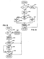
- FIGURES 12 and 13 illustrate detailed flow charts for the motor control routine 188 and motor driver routine 190, respectively.
- the program listings for these programs are found on page 9.
- the motor control routine 180 reads the location in memory where a run flag has been stored in block 240. If the run flag is set, then the program will branch to block 244. If the run flag has not been set, the motor will be stopped by functional block 242 and the run flag cleared. Thereafter, the program will return to the processing of input data from the keyboard and its main loop monitor functions. When a run flag is detected, the number of clock counts for the speed set point of the motor will be computed in block 244.
- the program will determine whether the motor is to be started at this time by interrogating a location in memory which indicates whether this is the first time through the program. If not, the program returns, but otherwise, if all conditions are ready for the motor to be started, the motor is forced to run for a short period in block 248. Decisional block 250 will determine if there has been a timeout. Atimeoutwill cause the motor control routine to terminate and return control to the main monitor routine.
- the motor driver routine 190 begins in block 252 and is essentially a speed control loop called by the hardware interrupt produced from the optoelectric sensor.
- the first block determines whether the run flag is set and, if not, the motor is stopped in block 254 and the program returns to the monitor routine. If the run flag is set, then in block 256 the program reads the real time clock as an indication of the clock counts since the last interrupt. This time is stored in the variable TDR.
- the actual speed is compared to the set speed to determine whether the motor is operating either too fast or too slow. If the motor is operating slowly, the program will branch to block 262 wher the motor control signal is set to a level logic which will turn the motor fully on. In the alternative, if the motor is already going faster than the set point, then the control signal is turned off by block 260.
- the separate branches of the program consolidate at block 264 where the reference for the selected velocity variable is updated.
- the variable is updated from the motor control routine by adding the time period Td.
- the program then returns to the location in the monitor routine where the microprocessor was executing prior to the interrupt after performing its control and updating functions. The loop process continues until the predetermined period has elapsed as previously indicated.
- the microprocessor 100 when it receives an interrupt begins a counter clocked at the 65,536 Hz. frequency. When the next interrupt pulse appears, the microprocessor stores the clock count Tf for use as the actual speed. Now the variable X is calculated as
- the controller uses the interval comparison as a convenient and accurate method of controlling the speed of the motor. Since the interrupts occur every 2° of rotation for the motor, the actual speed is calculated 180 times per revolution providing an extremely accurate comparison standard.
- the program loop for the actual control is additionally executed quickly and permits many control onerations per revolution. The loop is executed in its simplest form by reading two constants, one from the timer register for the actual speed of the motor and the other from memory for the set speed of the motor and then doing the comparison and test steps. The tests and output control signal commands can be accomplished in the same instructions.
- this method is combined with a means to compensate for the cycles that the speed control is under or over the actual set speed. In this manner the system actually maintains a tight speed control while providing compensation to ensure the total number of cycles for the predetermined time period are correct.
- TDR real time clock
- REFTIML reference time variable
- REFTIMH reference time variable
- the reference time variable is incremental by an incremental clock count MTRDT based on what should be the correct number at the selected speed. This total number should equal the real time clock number TDR if the speed is that desired. If the motor is slow and cycles are being lost than the motor is speeded up until both are equal. If the motor is fast and cycles are being added then the motor is slowed down until both are equal.
- a speed control in combination with a cycle equalization method has thus been disclosed.
- FIGURE 10 Waveform diagrams for a control operated in this manner are illustrated in FIGURE 10 where the interrupt pulses from the optoelectric sensor are illustrated as the waveform INT.
- the velocity profile for the motor speed as a function of time is shown in the waveform labelled V where speed set point S1 and speed set point S2 will be used to explain operation of the control.
- the operator At the start of an interval, the operator has previously input a time duration over which the agitation will occur. As further input, a speed is set at which he desires the test or agitation to occur, in the example S1, initially. The operator presses the start button and the control thereafter will bring the shaker up to the set point speed and maintain it at that speed precisely for the duration of the interval.
- the motor starts at rest and therefore the control signal CO is set to a high level indicating that the motor is running slower than the set point velocity. This function is provided by the motor control routine forcing the interrupts to occur at a motor start so that the motor drive routine can take control.
- the velocity will begin to ramp at a particular rate shown by the slope of the velocity level 156. As time passes, this velocity level will approach the set point S1 and finally exceed it.
- the control signal CO is set to a low logic level as illustrated at 152. Turning off the drive signal to the motor causes it to freewheel and the velocity to fall at a characteristic slope as shown by 158.
- the interrupt signal INT provides a method for determining when the actual velocity V crosses the set point.
- the INT pulses begin to come at a higher frequency where two successive pulses 140 and 142 are closer together than the previous two successive pulses. It is seen that at the highest velocity the pulses are the closest together at 144. The pulses then begin to spread out and lower in frequency as the motor slows because of the low logic level on the signal line CO as seen at 146 which corresponds to slope 158. Thereafter, when the controller reaches a limit cycle at 160 the corresponding interrupt pulses at 148 are relatively equal in spacing.
- This type of controller is termed a "bang-bang" type control where the slope 158 for deceleration is substantially different than the slope for acceleration. This is caused by the amnner in which the motor is controlled by the control signal CO and the configuration of the motor including the counterweight.
- the acceleration slope is determined by the full on drive produced by the control when the motor speed is less than the set point.
- the motor speed then coasts down when the drive is turned at a rate determined by the flywheel effect of the counterweight. This produces an advantageous control which may precisely maintain the speed of the rotation for the specimen tray 14 within ⁇ 1% of set point over a range of between 40 and 250 RPMs.
Landscapes
- Chemical & Material Sciences (AREA)
- Chemical Kinetics & Catalysis (AREA)
- Physics & Mathematics (AREA)
- General Physics & Mathematics (AREA)
- Engineering & Computer Science (AREA)
- Power Engineering (AREA)
- Sampling And Sample Adjustment (AREA)
- Mixers With Rotating Receptacles And Mixers With Vibration Mechanisms (AREA)
- Control Of Velocity Or Acceleration (AREA)
- Control Of Direct Current Motors (AREA)
- Automatic Analysis And Handling Materials Therefor (AREA)
Claims (11)
Priority Applications (1)
| Application Number | Priority Date | Filing Date | Title |
|---|---|---|---|
| AT85903766T ATE60137T1 (de) | 1984-07-19 | 1985-07-18 | Umlaufender ruettler. |
Applications Claiming Priority (2)
| Application Number | Priority Date | Filing Date | Title |
|---|---|---|---|
| US06/632,574 US4673297A (en) | 1984-07-19 | 1984-07-19 | Orbital shaker |
| US632574 | 1984-07-19 |
Publications (3)
| Publication Number | Publication Date |
|---|---|
| EP0188576A1 EP0188576A1 (de) | 1986-07-30 |
| EP0188576A4 EP0188576A4 (de) | 1988-02-01 |
| EP0188576B1 true EP0188576B1 (de) | 1991-01-16 |
Family
ID=24536068
Family Applications (1)
| Application Number | Title | Priority Date | Filing Date |
|---|---|---|---|
| EP85903766A Expired EP0188576B1 (de) | 1984-07-19 | 1985-07-18 | Umlaufender rüttler |
Country Status (6)
| Country | Link |
|---|---|
| US (1) | US4673297A (de) |
| EP (1) | EP0188576B1 (de) |
| JP (1) | JPS61502733A (de) |
| CA (1) | CA1278072C (de) |
| DE (1) | DE3581390D1 (de) |
| WO (1) | WO1986000995A1 (de) |
Cited By (1)
| Publication number | Priority date | Publication date | Assignee | Title |
|---|---|---|---|---|
| US9511334B2 (en) | 2013-08-29 | 2016-12-06 | Burrell Scientific LLC | Clamp for a fluid container and method of use thereof |
Families Citing this family (37)
| Publication number | Priority date | Publication date | Assignee | Title |
|---|---|---|---|---|
| US5060151A (en) * | 1984-07-19 | 1991-10-22 | Cymatics, Inc. | Speed control for orbital shaker with reversing mode |
| US4828395A (en) * | 1985-02-21 | 1989-05-09 | Yamato Scientific Company, Limited | Continuous flow type homogenizer |
| CA1324427C (en) * | 1987-06-15 | 1993-11-16 | Glenn Emil Mikyska | Speed control for orbital shaker with reversing mode |
| US5066135A (en) * | 1988-08-09 | 1991-11-19 | Beckman Instruments, Inc. | Rotatable vortexing turntable |
| GB9008827D0 (en) * | 1990-04-19 | 1990-06-13 | Fisons Plc | Device |
| US5052812A (en) * | 1990-11-19 | 1991-10-01 | New Brunswick Scientific Co., Inc. | Bath shaker |
| US5184893A (en) * | 1991-03-25 | 1993-02-09 | Kerr Manufacturing Company | Automatic capsule mixing device |
| SE500613C2 (sv) * | 1991-09-20 | 1994-07-25 | Hilda Barbro Hjalmarson | Blandningsapparat omfattande en för mottagning av provtagningsrör avsedd blandningsplatta, som bibringas en vaggningsrörelse av viss frekvens |
| USD340249S (en) | 1992-02-14 | 1993-10-12 | Kerr Manufacturing Company | Automatic capsule mixing device |
| FI922003A7 (fi) * | 1992-05-04 | 1993-11-19 | Wallac Oy | Ravistelija/inkubaattori |
| DE4300748A1 (de) * | 1993-01-14 | 1994-07-21 | Heidolph Elektro Gmbh & Co Kg | Schüttel- und Mischgerät |
| US5499872A (en) * | 1994-03-14 | 1996-03-19 | Baxter; Michael | Turntable mixer apparatus |
| GB9411971D0 (en) * | 1994-06-15 | 1994-08-03 | Fletcher David J | Shaker device |
| US5558437A (en) * | 1995-05-19 | 1996-09-24 | Forma Scientific, Inc. | Dynamically balanced orbital shaker |
| US5564826A (en) * | 1995-09-27 | 1996-10-15 | Robbins Scientific Corporation | Reciprocating bath shaker |
| US5593228A (en) * | 1996-05-03 | 1997-01-14 | New Brunswick Scientific Co., Inc. | Rotary shaker with flexible strap suspension |
| KR100470754B1 (ko) * | 2002-11-27 | 2005-02-21 | 주식회사 엔바이오텍 | 진탕기 |
| US7075040B2 (en) * | 2003-08-21 | 2006-07-11 | Barnstead/Thermolyne Corporation | Stirring hot plate |
| US20050183582A1 (en) * | 2003-08-21 | 2005-08-25 | Mcfadden Curt | Controls for magnetic stirrer and/or hot plate |
| RU2260897C2 (ru) * | 2003-09-23 | 2005-09-20 | Государственное образовательное учреждение высшего профессионального образования "Ивановский государственный энергетический университет им. В.И. Ленина" (ИГЭУ) | Электропривод |
| US7438462B1 (en) | 2004-03-18 | 2008-10-21 | Bodie Christine J | System or method for shaking a container |
| US7296923B1 (en) * | 2004-12-16 | 2007-11-20 | Stovall Life Science, Inc. | Drive mechanism for mixing device |
| DE102006011370A1 (de) * | 2006-03-09 | 2007-09-20 | Eppendorf Ag | Vorrichtung zum Mischen insbesondere von Laborgefäß-Inhalten mit einem Sensor |
| DE102006062714B4 (de) * | 2006-03-09 | 2013-02-21 | Eppendorf Ag | Vorrichtung zum Mischen von Laborgefäß-Inhalten |
| US8393781B2 (en) * | 2006-09-06 | 2013-03-12 | Henry Troemner Llc | Incubating orbital shaker |
| JP5431964B2 (ja) | 2007-02-07 | 2014-03-05 | セントロ デ インヴェスティガシオン デ ロタシオン イ トルク アプリカーダ,エセ.エレ. | 電磁軸攪拌装置 |
| US9016930B2 (en) * | 2007-09-28 | 2015-04-28 | Metal Shapes, Inc. | Apparatus for moving liquid in container |
| US8960992B2 (en) * | 2008-04-16 | 2015-02-24 | Koninklijke Philips N.V. | Bottle warmer and mixing apparatus |
| RU2422978C1 (ru) * | 2010-05-24 | 2011-06-27 | Государственное Образовательное Учреждение Высшего Профессионального Образования "Омский Государственный Технический Университет" | Синхронно-синфазный электропривод |
| US8534905B2 (en) * | 2010-05-24 | 2013-09-17 | New Brunswick Scientific Co., Inc. | Adjustable orbit imbalance compensating orbital shaker |
| US8226291B2 (en) * | 2010-05-24 | 2012-07-24 | New Brunswick Scientific Co., Inc. | Adjustable orbit imbalance compensating orbital shaker |
| JP6351113B2 (ja) * | 2015-01-29 | 2018-07-04 | 藤森工業株式会社 | 振とう型培養装置及びこれを用いた培養方法 |
| ES2904514T3 (es) * | 2015-04-06 | 2022-04-05 | Meso Scale Technologies Llc | Sistema de alto rendimiento para realizar ensayos mediante el uso de electroquimioluminiscencia que incluye un aparato de agitación de consumibles |
| US10093960B2 (en) * | 2015-07-24 | 2018-10-09 | Molecular Devices, Llc | Luminescence measurement of biological samples utilizing dual reagents |
| US10881113B2 (en) | 2016-09-30 | 2021-01-05 | Burford Corporation | Automated pan shaker with multiple modes of movement |
| USD898088S1 (en) * | 2018-04-30 | 2020-10-06 | Firmenich Sa | Flavor mixing machine |
| CN112826676A (zh) * | 2021-01-09 | 2021-05-25 | 刘小芳 | 一种儿科护理智能摇床 |
Family Cites Families (29)
| Publication number | Priority date | Publication date | Assignee | Title |
|---|---|---|---|---|
| US2255799A (en) * | 1939-08-05 | 1941-09-16 | Gotthold H Meinzer | Shaker |
| US2500293A (en) * | 1944-06-09 | 1950-03-14 | O Connor Patent Company | Vibratory dump truck |
| US2756973A (en) * | 1952-12-10 | 1956-07-31 | Prep Ind Combustibles | Dynamically balanced vibrating agitators |
| US2793010A (en) * | 1956-05-18 | 1957-05-21 | Menken Shepard | Agitation apparatus |
| US3173664A (en) * | 1963-07-01 | 1965-03-16 | Isaacson | Vibrator |
| US3310292A (en) * | 1964-03-13 | 1967-03-21 | American Hospital Supply Corp | Serological testing device |
| US3297304A (en) * | 1965-02-08 | 1967-01-10 | Eugene A Wahl | Vibratory conveyor-mixer apparatus |
| CH450749A (de) * | 1966-01-20 | 1968-01-31 | Wirth Gallo & Co | Uberlastsicherung für Messapparate, insbesondere für Waagen |
| FR1564549A (de) * | 1967-01-17 | 1969-04-25 | ||
| US3430926A (en) * | 1967-09-12 | 1969-03-04 | New Brunswick Scientific Co | Counterweight system for shaker apparatus |
| DE2137277C2 (de) * | 1971-07-26 | 1982-05-13 | Dietmar Prof. Dr.-Ing.habil. 5100 Aachen Boenisch | Vorrichtung zum Mischen von Stoffen, insbesondere Gießereiformstoffen |
| GB1425924A (en) * | 1972-05-18 | 1976-02-25 | Russel Finex | Vibratory apparatus |
| US3838321A (en) * | 1973-10-24 | 1974-09-24 | Owens Illinois Inc | Speed control system |
| US4109319A (en) * | 1975-12-18 | 1978-08-22 | Spectroderm International | Agitator for laboratory tubes and flasks and the like |
| US4061315A (en) * | 1976-06-16 | 1977-12-06 | American Hospital Supply Corporation | Orbital platform stirring system |
| US4202634A (en) * | 1976-11-05 | 1980-05-13 | Kraft Harold D | Rack for vessels and means for agitating the vessels in the rack |
| US4118801A (en) * | 1976-11-05 | 1978-10-03 | Kraft Jack A | Rack for vessels and means for agitating the vessels in the rack |
| US4138723A (en) * | 1977-08-12 | 1979-02-06 | General Motors Corporation | Motor vehicle speed control system |
| JPS5924637B2 (ja) * | 1978-07-03 | 1984-06-11 | 株式会社東芝 | デイジタル速度制御装置 |
| US4244513A (en) * | 1978-09-15 | 1981-01-13 | Coulter Corporation | Centrifuge unit |
| JPS56101037A (en) * | 1980-01-18 | 1981-08-13 | Nissan Motor Co Ltd | System for operating vehicle at constant speed |
| US4305668A (en) * | 1980-04-08 | 1981-12-15 | Scientific Manufacturing Industries, Inc. | Vortexer |
| FR2486731A1 (fr) * | 1980-07-11 | 1982-01-15 | Cii Honeywell Bull | Dispositif de regulation de la vitesse de rotation d'un moteur electrique |
| US4403867A (en) * | 1980-10-20 | 1983-09-13 | Horace Duke | Ink and water tester |
| US4434470A (en) * | 1981-02-09 | 1984-02-28 | The Bendix Corporation | Speed measurement system with means for calculating the exact time period of a known quantity of speed pulses |
| FR2506345B1 (fr) * | 1981-05-20 | 1988-06-24 | Truetzschler Gmbh & Co Kg | Dispositif de commande et de regulation d'une carde |
| US4506312A (en) * | 1982-03-09 | 1985-03-19 | Ford Aerospace & Communications Corporation | Apparatus for controlling the speed of a rotating body |
| US4523653A (en) * | 1984-03-08 | 1985-06-18 | Frazier Precision Instrument Company, Inc. | Load cell mass comparator |
| US4523855A (en) * | 1984-05-02 | 1985-06-18 | Walker Robert L | Shaker |
-
1984
- 1984-07-19 US US06/632,574 patent/US4673297A/en not_active Expired - Lifetime
-
1985
- 1985-07-16 CA CA000486859A patent/CA1278072C/en not_active Expired - Lifetime
- 1985-07-18 DE DE8585903766T patent/DE3581390D1/de not_active Expired - Fee Related
- 1985-07-18 JP JP60503327A patent/JPS61502733A/ja active Pending
- 1985-07-18 EP EP85903766A patent/EP0188576B1/de not_active Expired
- 1985-07-18 WO PCT/US1985/001370 patent/WO1986000995A1/en not_active Ceased
Cited By (1)
| Publication number | Priority date | Publication date | Assignee | Title |
|---|---|---|---|---|
| US9511334B2 (en) | 2013-08-29 | 2016-12-06 | Burrell Scientific LLC | Clamp for a fluid container and method of use thereof |
Also Published As
| Publication number | Publication date |
|---|---|
| WO1986000995A1 (en) | 1986-02-13 |
| EP0188576A4 (de) | 1988-02-01 |
| DE3581390D1 (de) | 1991-02-21 |
| EP0188576A1 (de) | 1986-07-30 |
| JPS61502733A (ja) | 1986-11-27 |
| US4673297A (en) | 1987-06-16 |
| CA1278072C (en) | 1990-12-18 |
Similar Documents
| Publication | Publication Date | Title |
|---|---|---|
| EP0188576B1 (de) | Umlaufender rüttler | |
| US5060151A (en) | Speed control for orbital shaker with reversing mode | |
| US5287050A (en) | Method of synchronization for an indicating instrument with electromagnetically controlled stepping motor | |
| US5052812A (en) | Bath shaker | |
| US5392706A (en) | Pad transfer printing method | |
| GB1558682A (en) | Electrical balance | |
| CN1058336C (zh) | 检测搅拌流体重量的方法和装置 | |
| US5409101A (en) | Variably-controlled vibratory conveyor | |
| US4847544A (en) | Microcomputer control of stepper motor using reduced number of parts | |
| US4328701A (en) | Apparatus for determining the behavior of a liquid during coagulation and the like | |
| DK1086827T3 (da) | Indretning til at holde en given viskositet konstant i et klæbemiddel til limning af en bogblokryg eller et bogbind | |
| EP0295850B1 (de) | Geschwinigkeitsregelung für einen umlaufenden Rüttler mit Umkehrmodus | |
| KR850001852A (ko) | 로보트의 동작 제어장치 | |
| US5006773A (en) | Microcomputer control of stepper motor using reduced number of parts | |
| CA2022266A1 (en) | Automatic washer with controlled stroke parameter | |
| US6701219B2 (en) | Control method for a link arm mechanism and an automatic centrifugal machine employing this link arm mechanism | |
| JPH057675A (ja) | 自動縫いミシンの制御装置 | |
| EP0271590A4 (en) | Robot control apparatus | |
| EP0403658A1 (de) | Geschwindigkeitsregelverfahren für einen servomotor | |
| KR100297111B1 (ko) | 진탕기 | |
| JP2577686B2 (ja) | 部品の自動計数装置 | |
| CA2085261A1 (en) | Mailing machine including printing drum control system | |
| JPH11262881A (ja) | リンクアーム機構の制御方法 | |
| US5130096A (en) | Titrating system including pulse length modulation means | |
| US20010023657A1 (en) | Sewing machine |
Legal Events
| Date | Code | Title | Description |
|---|---|---|---|
| PUAI | Public reference made under article 153(3) epc to a published international application that has entered the european phase |
Free format text: ORIGINAL CODE: 0009012 |
|
| 17P | Request for examination filed |
Effective date: 19860310 |
|
| AK | Designated contracting states |
Kind code of ref document: A1 Designated state(s): AT BE CH DE FR GB IT LI LU NL SE |
|
| A4 | Supplementary search report drawn up and despatched |
Effective date: 19880201 |
|
| 17Q | First examination report despatched |
Effective date: 19890616 |
|
| GRAA | (expected) grant |
Free format text: ORIGINAL CODE: 0009210 |
|
| AK | Designated contracting states |
Kind code of ref document: B1 Designated state(s): AT BE CH DE FR GB IT LI LU NL SE |
|
| PG25 | Lapsed in a contracting state [announced via postgrant information from national office to epo] |
Ref country code: IT Free format text: LAPSE BECAUSE OF FAILURE TO SUBMIT A TRANSLATION OF THE DESCRIPTION OR TO PAY THE FEE WITHIN THE PRESCRIBED TIME-LIMIT;WARNING: LAPSES OF ITALIAN PATENTS WITH EFFECTIVE DATE BEFORE 2007 MAY HAVE OCCURRED AT ANY TIME BEFORE 2007. THE CORRECT EFFECTIVE DATE MAY BE DIFFERENT FROM THE ONE RECORDED. Effective date: 19910116 Ref country code: SE Effective date: 19910116 Ref country code: BE Effective date: 19910116 Ref country code: LI Effective date: 19910116 Ref country code: NL Effective date: 19910116 Ref country code: CH Effective date: 19910116 Ref country code: AT Effective date: 19910116 |
|
| REF | Corresponds to: |
Ref document number: 60137 Country of ref document: AT Date of ref document: 19910215 Kind code of ref document: T |
|
| REF | Corresponds to: |
Ref document number: 3581390 Country of ref document: DE Date of ref document: 19910221 |
|
| ET | Fr: translation filed | ||
| REG | Reference to a national code |
Ref country code: CH Ref legal event code: PL |
|
| NLV1 | Nl: lapsed or annulled due to failure to fulfill the requirements of art. 29p and 29m of the patents act | ||
| PG25 | Lapsed in a contracting state [announced via postgrant information from national office to epo] |
Ref country code: LU Free format text: LAPSE BECAUSE OF NON-PAYMENT OF DUE FEES Effective date: 19910731 |
|
| PLBE | No opposition filed within time limit |
Free format text: ORIGINAL CODE: 0009261 |
|
| STAA | Information on the status of an ep patent application or granted ep patent |
Free format text: STATUS: NO OPPOSITION FILED WITHIN TIME LIMIT |
|
| 26N | No opposition filed | ||
| PGFP | Annual fee paid to national office [announced via postgrant information from national office to epo] |
Ref country code: GB Payment date: 19950707 Year of fee payment: 11 |
|
| PGFP | Annual fee paid to national office [announced via postgrant information from national office to epo] |
Ref country code: FR Payment date: 19950719 Year of fee payment: 11 |
|
| PGFP | Annual fee paid to national office [announced via postgrant information from national office to epo] |
Ref country code: DE Payment date: 19950731 Year of fee payment: 11 |
|
| PG25 | Lapsed in a contracting state [announced via postgrant information from national office to epo] |
Ref country code: GB Effective date: 19960718 |
|
| GBPC | Gb: european patent ceased through non-payment of renewal fee |
Effective date: 19960718 |
|
| PG25 | Lapsed in a contracting state [announced via postgrant information from national office to epo] |
Ref country code: FR Effective date: 19970328 |
|
| PG25 | Lapsed in a contracting state [announced via postgrant information from national office to epo] |
Ref country code: DE Effective date: 19970402 |
|
| REG | Reference to a national code |
Ref country code: FR Ref legal event code: ST |