EP0188646A1 - Einfach geregelte Stromversorgung mit Lastkompensation von einem Hilfsspannungsausgang - Google Patents
Einfach geregelte Stromversorgung mit Lastkompensation von einem Hilfsspannungsausgang Download PDFInfo
- Publication number
- EP0188646A1 EP0188646A1 EP85100687A EP85100687A EP0188646A1 EP 0188646 A1 EP0188646 A1 EP 0188646A1 EP 85100687 A EP85100687 A EP 85100687A EP 85100687 A EP85100687 A EP 85100687A EP 0188646 A1 EP0188646 A1 EP 0188646A1
- Authority
- EP
- European Patent Office
- Prior art keywords
- output
- voltage
- auxiliary
- power supply
- main
- Prior art date
- Legal status (The legal status is an assumption and is not a legal conclusion. Google has not performed a legal analysis and makes no representation as to the accuracy of the status listed.)
- Granted
Links
Images

Classifications
-
- H—ELECTRICITY
- H02—GENERATION; CONVERSION OR DISTRIBUTION OF ELECTRIC POWER
- H02M—APPARATUS FOR CONVERSION BETWEEN AC AND AC, BETWEEN AC AND DC, OR BETWEEN DC AND DC, AND FOR USE WITH MAINS OR SIMILAR POWER SUPPLY SYSTEMS; CONVERSION OF DC OR AC INPUT POWER INTO SURGE OUTPUT POWER; CONTROL OR REGULATION THEREOF
- H02M3/00—Conversion of DC power input into DC power output
- H02M3/22—Conversion of DC power input into DC power output with intermediate conversion into AC
- H02M3/24—Conversion of DC power input into DC power output with intermediate conversion into AC by static converters
- H02M3/28—Conversion of DC power input into DC power output with intermediate conversion into AC by static converters using discharge tubes with control electrode or semiconductor devices with control electrode to produce the intermediate AC
- H02M3/325—Conversion of DC power input into DC power output with intermediate conversion into AC by static converters using discharge tubes with control electrode or semiconductor devices with control electrode to produce the intermediate AC using devices of a triode or a transistor type requiring continuous application of a control signal
- H02M3/335—Conversion of DC power input into DC power output with intermediate conversion into AC by static converters using discharge tubes with control electrode or semiconductor devices with control electrode to produce the intermediate AC using devices of a triode or a transistor type requiring continuous application of a control signal using semiconductor devices only
- H02M3/33561—Conversion of DC power input into DC power output with intermediate conversion into AC by static converters using discharge tubes with control electrode or semiconductor devices with control electrode to produce the intermediate AC using devices of a triode or a transistor type requiring continuous application of a control signal using semiconductor devices only having more than one ouput with independent control
-
- H—ELECTRICITY
- H02—GENERATION; CONVERSION OR DISTRIBUTION OF ELECTRIC POWER
- H02M—APPARATUS FOR CONVERSION BETWEEN AC AND AC, BETWEEN AC AND DC, OR BETWEEN DC AND DC, AND FOR USE WITH MAINS OR SIMILAR POWER SUPPLY SYSTEMS; CONVERSION OF DC OR AC INPUT POWER INTO SURGE OUTPUT POWER; CONTROL OR REGULATION THEREOF
- H02M1/00—Details of apparatus for conversion
- H02M1/0083—Converters characterised by their input or output configuration
- H02M1/009—Converters characterised by their input or output configuration having two or more independently controlled outputs
Definitions
- the present invention relates to a single regulation power supply with Load compensation of an auxiliary voltage output.
- the present invention overcomecsuch limitation and provides a very simple and unexpensive means to achieve a load compensation of an unregulated auxiliary output through the regulation of a main output voltage and with the trade off of a slight and generally acceptable degradation of the main output voltage regulation characteristic.
- this result is achieved in a single regulation power supply of the converter type having a main regulated output and a se condary unregulated output series connected to the main output to provide an auxiliary output voltage by the insertion in the regula tion Loop of the main output of a resistor passed through by the Load current of the auxiliary output, the value of such resistor having a preestablished relation with the internal resistance of the main out put voltage generator and the secondary output voltage generator.
- the regulation loop controls the sum of the voltage at the main output with the voltage drop on such resistor, keeping the summing volta ge constant.
- the voltage at the main output differs from the regulated voltage by the minimum amount of voltage drop on the resistor, and good regulation characteristics are maintained.
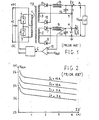
- the power supply comprises a transformer TR having a center tapped primary winding 1, a center tapped main secondary winding 2 and a cen ter tapped auxiliary secondary winding 3.
- the center tap of primary winding 1 is connected to a +DC terminal.
- the terminals of primary winding 1 are each connected to a -DC terminal through switch 4, 5 respectively.
- the center tap of secondary winding 2 is connected to ground and the terminals are each connected through a diode 7, 8 respectively and through an inductor 9 to a main output terminal M.
- a capacitor 10 is connected between terminal M and ground.
- the center tap T of secondary winding 3 is connected to main output terminal M.
- the terminals of secondary winding 3 are each connected, through a diode 11, 12 respectively and through an inductor 13 to an auxiliary output terminal A.
- a capacitor 14 is connected between terminal A and terminal M.
- An unregulated DC input voltage VI is applied between the input termi nals +DC, -DC.
- the two switches 4, 5 are controlled by a pulse width modulator 6 to switch on in mutually exclusive way, thus allowing an energizing cur rent to alternatively flow in each of the half portions of primary winding during periodic time intervals of controlled duration.
- the alternating voltage pulses induced in secondary winding 2 are rec tified by diodes 7, 8 filtered by LC network 9, 10 and provide a main output voltage V 1 between terminal M and ground.
- Terminal M is connected to a signal input of an error amplifier 15 receiving a reference voltage level V REF at a reference input.
- the error amplifier 15 provides an error signal to a control input of pulse width modulator 6, which in turn controls the time on, time off interval of switches 4, 5 so as to keep V 1 very close to the referee ce voltage V REF and practically constant, irrespective of voltage changes in the input voltage VI and/or changes in the main load connected to output M and shown as L 1 .
- the alternating voltage pulses induced in secondary winding 3, are rectified by diodes 11, 12, filtered by LC network 13, 14 and provide a secondary output voltage V 2 between terminal A and terminal M.
- An auxiliary voltage V AUX is available between terminal A and ground to feed a second load shown as L2.
- the auxiliary voltage V AUX has the following peculiarities.
- V2 V1
- V AUX which is represented by V 1 , is unaffect ed by voltage changes of VI, nor by load changes of L 1 , L Z .
- VAUX which is represented by V 2
- VI changes which are recovered by the regulation loop at the advantage of V 2 too.
- FIG. 2 shows a tipical family of curbes, expres sing V AUX (hence V 2 ) as a function of the current I 1 (taken as para meter), drained by the main Load L 1 , and of the current I drained by the Load L 2 at the auxiliary output, for a power supply designed to provide a main output, regulated voltage of +5V within a Load range I 1 from 3 to 15 amperes, and an auxiliary output voltage, nominally 25 V within a Load range I 2 from 0,5 to 4 Amperes.
- V AUX is expressed as a function of current I 1 and current I 2 is taken as parameter.
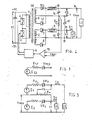
- V AUX is a linear function of I 1 , I 2 , and confirm the theoretical approach explained in the above mentioned article, that the output stages of the power supply shown in Fig. 1 may each be represented by the equi valent circuit shown in Fig. 3.
- Each secondary winding 2, 3 acts as a perfect voltage generator E 2,3 -Each diode acts as a fixed voltage drop V F2,3 (the forward voltage drop of each diode).
- each secondary winding 2, 3 and each induc tor 13, 9 acts as a resistor R 1,2 .
- the index 2, 3 affixed to the components of the equivalent circuit re Lates the components to the main output stage (index 2) or to the se condary output stage (index 3).
- the power supply shown in Fig. 1 is modi fied as shown in Fig. 4.
- the circuit of Fig. 4 differs from the one of Fig. 1 only in that center tap T of secondary winding 3 is connected to terminal M of the main output stage through a resistor R x and in that the signal input of error amplifier 15 is connected to center tap T instead of terminal M.
- the auxiliary voltage V AUX can be rendered completely independent from I 2.
- Fig. 5 shows the equivalent circuit for the embodiment of Fig. 4, as can be easily drawn from the considerations previously developped. From the equivalent circuit of Fig. 5, where the regulated voltage is • V REG instead of V 1 it is clear that:
- V REG , V F2 , VF3 are constant and V AUX is clearly dependent on I and I 2.
- a tipical example may be found in electronic printers and personal EDP systems, which may requi re the powering of logical circuits at +5V with current load of 10 Amp. substantially constant, whilst the energization of the printer head, and printer motors, may require powering at +25 V with current Load va riable between 1 to 4 Amp.
- a power supply may be designed according to the diagram of Fig. 4, which in order to achieve high efficiency privileges the copper sizing of the main output winding and filter, against the sizing of the auxiliary winding.
- LeveL of V 2 would have been affected by load changes at the auxiliary output in the much Larger amount of about 430 mV.
- R x may be selected to have a value of 17 m ⁇ , by which changes of V 1 are contained within 51 mV (1% of 5V) and changes of V 2 are contained within 246 mV (1% of 25V).
- FIG. 4 shows a preferred embodiment of the invention and that several changes can be made without departing from the scope of the invention.
- the embodimeng of Fig. 4 provides a common ground LeveL for both the main output as well as the auxiliary output.
- resistor R X is on the ground connection side of the auxiliary output, instead of the connection point between main output stage and secondary output stage.
- the secondary output stage needs not to be series connected with the main output stage and can provide an auxiliary output voltage independently from the main output voltage.
- the power supply has been shown as a full wave converter, it may take the form of a half way converter, and the windings, which have been shown as center tapped, may be single windings provided with suitable rectifying bridges at the output, and suitably driving circuits at the input.
- turnon/turnoff ratio of the energizing pulse may be changed, for regulation purpose either by means of pulse width modulation circuits as well as by means of frequency modulation circuits.
- the core of the invention resides,fora power supply con verter where pulses fed to the input of a transformer induce pulses in winding of a main output section and in a winding of an auxiliary output section, the voltage at the main output being regulated through a control Loop which senses the voltage at the main output and control the pulsed energization of the power supply, in the inclusion in the control Loop of a resistor for sensing the current Load at the auxiliary output, the voltage drop across said resistor being algebraical Ly added to the main output voltage.
- a small capacity capacitor 17, is preferably added in parallel to resistor R x , (or between tap T and ground, as shown in Fig. 4) for the purpose of achieving stability of the control Loop and rendering it un sensitive to sudden changes in the auxiliary output Load L 2 .
Landscapes
- Engineering & Computer Science (AREA)
- Power Engineering (AREA)
- Dc-Dc Converters (AREA)
Priority Applications (3)
| Application Number | Priority Date | Filing Date | Title |
|---|---|---|---|
| EP85100687A EP0188646B1 (de) | 1985-01-24 | 1985-01-24 | Einfach geregelte Stromversorgung mit Lastkompensation von einem Hilfsspannungsausgang |
| DE8585100687T DE3575055D1 (de) | 1985-01-24 | 1985-01-24 | Einfach geregelte stromversorgung mit lastkompensation von einem hilfsspannungsausgang. |
| US06/820,768 US4660136A (en) | 1985-01-24 | 1986-01-21 | Single regulation power supply with load compensation of an auxiliary voltage output |
Applications Claiming Priority (1)
| Application Number | Priority Date | Filing Date | Title |
|---|---|---|---|
| EP85100687A EP0188646B1 (de) | 1985-01-24 | 1985-01-24 | Einfach geregelte Stromversorgung mit Lastkompensation von einem Hilfsspannungsausgang |
Publications (2)
| Publication Number | Publication Date |
|---|---|
| EP0188646A1 true EP0188646A1 (de) | 1986-07-30 |
| EP0188646B1 EP0188646B1 (de) | 1989-12-27 |
Family
ID=8193250
Family Applications (1)
| Application Number | Title | Priority Date | Filing Date |
|---|---|---|---|
| EP85100687A Expired EP0188646B1 (de) | 1985-01-24 | 1985-01-24 | Einfach geregelte Stromversorgung mit Lastkompensation von einem Hilfsspannungsausgang |
Country Status (3)
| Country | Link |
|---|---|
| US (1) | US4660136A (de) |
| EP (1) | EP0188646B1 (de) |
| DE (1) | DE3575055D1 (de) |
Cited By (1)
| Publication number | Priority date | Publication date | Assignee | Title |
|---|---|---|---|---|
| CN106664026A (zh) * | 2014-09-25 | 2017-05-10 | 英特尔公司 | 适于不同功率模式的电源单元 |
Families Citing this family (69)
| Publication number | Priority date | Publication date | Assignee | Title |
|---|---|---|---|---|
| US4725937A (en) * | 1985-01-08 | 1988-02-16 | Westinghouse Electric Corp. | Low power dissipation analog current loop output circuit |
| US4937730A (en) * | 1988-10-25 | 1990-06-26 | Daykin Electric Corporation | Constant voltage power supply |
| JPH07118918B2 (ja) * | 1989-01-26 | 1995-12-18 | 三菱電機株式会社 | Dc/dc電源装置 |
| US4935858A (en) * | 1989-09-05 | 1990-06-19 | Motorola, Inc. | Auxiliary output regulation technique for power supplies |
| IT1231052B (it) * | 1989-09-27 | 1991-11-12 | Bull Hn Information Syst | Alimentatore a commutazione con piu' uscite, regolazione di una tensione di uscita e compensazione di carico. |
| DE8912879U1 (de) * | 1989-10-31 | 1990-02-08 | C. Fülbier und K. Valicek Conway GmbH, 8000 München | Netzteil zum Netzanschluß von elektrischen oder elektronischen Geräten |
| JP3132093B2 (ja) * | 1991-09-25 | 2001-02-05 | ヤマハ株式会社 | 電源回路 |
| DE4237167C2 (de) * | 1991-11-14 | 2003-04-17 | Perkin Elmer Corp | Vorrichtung zum geregelten Beheizen einer Ionenquelle eines thermionischen Detektors |
| US5285367A (en) * | 1992-02-07 | 1994-02-08 | Power Integrations, Inc. | Linear load circuit to control switching power supplies under minimum load conditions |
| US5336985A (en) * | 1992-11-09 | 1994-08-09 | Compaq Computer Corp. | Tapped inductor slave regulating circuit |
| EP0602835B1 (de) * | 1992-12-15 | 1996-05-01 | AT&T Corp. | Spannungssteuerschaltungen |
| US5363323A (en) * | 1993-08-11 | 1994-11-08 | International Business Machines Corporation | Power supply with plural outputs supplying dynamic and steady loads |
| JPH07135771A (ja) * | 1993-11-09 | 1995-05-23 | Hitachi Ltd | 2出力dc−dcコンバータ |
| DE4424800A1 (de) * | 1994-07-14 | 1996-01-18 | Philips Patentverwaltung | Schaltungsanordnung zum Liefern von Speisespannungen |
| DE19548986C2 (de) * | 1995-12-28 | 1998-02-12 | Siemens Ag | Schaltungsanordnung zur Hilfsspannungserzeugung |
| DE19609123C2 (de) * | 1996-03-08 | 1998-01-29 | Siemens Ag | Schaltungsanordnung für Schaltnetzteile mit mehreren lastunabhängigen Ausgangsspannungen |
| US5895979A (en) * | 1997-09-23 | 1999-04-20 | Kojovic; Ljubomir A. | Power distribution network incorporating a voltage support transformer and process of use |
| US5933338A (en) * | 1997-10-14 | 1999-08-03 | Peco Ii, Inc. | Dual coupled current doubler rectification circuit |
| US6118679A (en) * | 1999-04-26 | 2000-09-12 | Astec International, Limited | Current sharing transformer circuit for power converters |
| JP2002244069A (ja) * | 2001-02-19 | 2002-08-28 | Nec Corp | レーザ走査光学装置及び該光学装置を用いたレーザ走査方法 |
| WO2002071586A2 (en) * | 2001-03-01 | 2002-09-12 | Koninklijke Philips Electronics N.V. | Power supply unit dc-dc conversion |
| DE10116156A1 (de) * | 2001-03-31 | 2002-10-10 | Philips Corp Intellectual Pty | Schaltungsanordnung zur Gewinnung einer Gleichspannung |
| US6501193B1 (en) * | 2001-09-07 | 2002-12-31 | Power-One, Inc. | Power converter having regulated dual outputs |
| US7280026B2 (en) | 2002-04-18 | 2007-10-09 | Coldwatt, Inc. | Extended E matrix integrated magnetics (MIM) core |
| US7427910B2 (en) * | 2004-08-19 | 2008-09-23 | Coldwatt, Inc. | Winding structure for efficient switch-mode power converters |
| US7321283B2 (en) * | 2004-08-19 | 2008-01-22 | Coldwatt, Inc. | Vertical winding structures for planar magnetic switched-mode power converters |
| US7372711B2 (en) * | 2005-01-11 | 2008-05-13 | Lineage Power Corporation | Circuit and method for reducing voltage spikes due to magnetizing current imbalances and power converter employing the same |
| US7417875B2 (en) * | 2005-02-08 | 2008-08-26 | Coldwatt, Inc. | Power converter employing integrated magnetics with a current multiplier rectifier and method of operating the same |
| US7876191B2 (en) * | 2005-02-23 | 2011-01-25 | Flextronics International Usa, Inc. | Power converter employing a tapped inductor and integrated magnetics and method of operating the same |
| US7176662B2 (en) * | 2005-02-23 | 2007-02-13 | Coldwatt, Inc. | Power converter employing a tapped inductor and integrated magnetics and method of operating the same |
| US7385375B2 (en) * | 2005-02-23 | 2008-06-10 | Coldwatt, Inc. | Control circuit for a depletion mode switch and method of operating the same |
| US7359222B2 (en) * | 2005-09-15 | 2008-04-15 | Power Integrations, Inc. | Method and apparatus to improve regulation of a power supply |
| US8595041B2 (en) * | 2006-02-07 | 2013-11-26 | Sap Ag | Task responsibility system |
| US8125205B2 (en) * | 2006-08-31 | 2012-02-28 | Flextronics International Usa, Inc. | Power converter employing regulators with a coupled inductor |
| US7675759B2 (en) * | 2006-12-01 | 2010-03-09 | Flextronics International Usa, Inc. | Power system with power converters having an adaptive controller |
| US7889517B2 (en) * | 2006-12-01 | 2011-02-15 | Flextronics International Usa, Inc. | Power system with power converters having an adaptive controller |
| US9197132B2 (en) | 2006-12-01 | 2015-11-24 | Flextronics International Usa, Inc. | Power converter with an adaptive controller and method of operating the same |
| US7667986B2 (en) * | 2006-12-01 | 2010-02-23 | Flextronics International Usa, Inc. | Power system with power converters having an adaptive controller |
| US7675758B2 (en) * | 2006-12-01 | 2010-03-09 | Flextronics International Usa, Inc. | Power converter with an adaptive controller and method of operating the same |
| US7468649B2 (en) * | 2007-03-14 | 2008-12-23 | Flextronics International Usa, Inc. | Isolated power converter |
| US8035254B2 (en) * | 2007-04-06 | 2011-10-11 | Power Integrations, Inc. | Method and apparatus for integrated cable drop compensation of a power converter |
| US7906941B2 (en) * | 2007-06-19 | 2011-03-15 | Flextronics International Usa, Inc. | System and method for estimating input power for a power processing circuit |
| US7764517B2 (en) * | 2007-11-02 | 2010-07-27 | National Semiconductor Corporation | Power supply with reduced power consumption when a load is disconnected from the power supply |
| CN101741260A (zh) * | 2008-11-19 | 2010-06-16 | 鸿富锦精密工业(深圳)有限公司 | 电源装置和变压装置 |
| WO2010083511A1 (en) * | 2009-01-19 | 2010-07-22 | Flextronics International Usa, Inc. | Controller for a power converter |
| US9088216B2 (en) | 2009-01-19 | 2015-07-21 | Power Systems Technologies, Ltd. | Controller for a synchronous rectifier switch |
| US9019061B2 (en) | 2009-03-31 | 2015-04-28 | Power Systems Technologies, Ltd. | Magnetic device formed with U-shaped core pieces and power converter employing the same |
| US8643222B2 (en) | 2009-06-17 | 2014-02-04 | Power Systems Technologies Ltd | Power adapter employing a power reducer |
| US8514593B2 (en) * | 2009-06-17 | 2013-08-20 | Power Systems Technologies, Ltd. | Power converter employing a variable switching frequency and a magnetic device with a non-uniform gap |
| US9077248B2 (en) | 2009-06-17 | 2015-07-07 | Power Systems Technologies Ltd | Start-up circuit for a power adapter |
| US8638578B2 (en) | 2009-08-14 | 2014-01-28 | Power System Technologies, Ltd. | Power converter including a charge pump employable in a power adapter |
| US8976549B2 (en) * | 2009-12-03 | 2015-03-10 | Power Systems Technologies, Ltd. | Startup circuit including first and second Schmitt triggers and power converter employing the same |
| US8520420B2 (en) * | 2009-12-18 | 2013-08-27 | Power Systems Technologies, Ltd. | Controller for modifying dead time between switches in a power converter |
| US8787043B2 (en) * | 2010-01-22 | 2014-07-22 | Power Systems Technologies, Ltd. | Controller for a power converter and method of operating the same |
| US9246391B2 (en) | 2010-01-22 | 2016-01-26 | Power Systems Technologies Ltd. | Controller for providing a corrected signal to a sensed peak current through a circuit element of a power converter |
| WO2011116225A1 (en) | 2010-03-17 | 2011-09-22 | Power Systems Technologies, Ltd. | Control system for a power converter and method of operating the same |
| US8792257B2 (en) | 2011-03-25 | 2014-07-29 | Power Systems Technologies, Ltd. | Power converter with reduced power dissipation |
| US8814327B2 (en) * | 2011-07-01 | 2014-08-26 | Canon Kabushiki Kaisha | Power supply apparatus and printing apparatus |
| US8792256B2 (en) | 2012-01-27 | 2014-07-29 | Power Systems Technologies Ltd. | Controller for a switch and method of operating the same |
| US9190898B2 (en) | 2012-07-06 | 2015-11-17 | Power Systems Technologies, Ltd | Controller for a power converter and method of operating the same |
| US9214264B2 (en) | 2012-07-16 | 2015-12-15 | Power Systems Technologies, Ltd. | Magnetic device and power converter employing the same |
| US9099232B2 (en) | 2012-07-16 | 2015-08-04 | Power Systems Technologies Ltd. | Magnetic device and power converter employing the same |
| US9379629B2 (en) | 2012-07-16 | 2016-06-28 | Power Systems Technologies, Ltd. | Magnetic device and power converter employing the same |
| US9106130B2 (en) | 2012-07-16 | 2015-08-11 | Power Systems Technologies, Inc. | Magnetic device and power converter employing the same |
| US9240712B2 (en) | 2012-12-13 | 2016-01-19 | Power Systems Technologies Ltd. | Controller including a common current-sense device for power switches of a power converter |
| US9300206B2 (en) | 2013-11-15 | 2016-03-29 | Power Systems Technologies Ltd. | Method for estimating power of a power converter |
| CN121218053A (zh) | 2021-11-05 | 2025-12-26 | 意法半导体(格勒诺布尔2)公司 | 电源电路 |
| FR3129004A1 (fr) * | 2021-11-05 | 2023-05-12 | Stmicroelectronics (Grenoble 2) Sas | Circuit d’alimentation |
| CN114499237A (zh) * | 2022-02-13 | 2022-05-13 | 北京周源科技有限公司 | 一种电源供应系统及方法 |
Citations (2)
| Publication number | Priority date | Publication date | Assignee | Title |
|---|---|---|---|---|
| DE3024721A1 (de) * | 1980-06-30 | 1982-01-21 | Siemens AG, 1000 Berlin und 8000 München | Gleichspannungsumrichter zur erzeugung mehrerer ausgangsspannungen |
| EP0048934A1 (de) * | 1980-09-29 | 1982-04-07 | Siemens Aktiengesellschaft | Anordnung mit einer Regeleinrichtung mit einem geregelten Kreis und einem damit gekoppelten weiteren Kreis |
Family Cites Families (4)
| Publication number | Priority date | Publication date | Assignee | Title |
|---|---|---|---|---|
| US4122514A (en) * | 1976-11-01 | 1978-10-24 | Hewlett-Packard Company | Direct current power supply |
| US4419723A (en) * | 1981-10-29 | 1983-12-06 | Bell Telephone Laboratories, Incorporated | Regulation of multiple-output DC-DC converters |
| JPS5889075A (ja) * | 1981-11-24 | 1983-05-27 | Hitachi Ltd | 共振形スイツチング電源装置 |
| US4581691A (en) * | 1984-04-23 | 1986-04-08 | At&T Bell Laboratories | Balanced constant current sensing circuit inherently immune to longitudinal currents |
-
1985
- 1985-01-24 EP EP85100687A patent/EP0188646B1/de not_active Expired
- 1985-01-24 DE DE8585100687T patent/DE3575055D1/de not_active Expired - Lifetime
-
1986
- 1986-01-21 US US06/820,768 patent/US4660136A/en not_active Expired - Fee Related
Patent Citations (2)
| Publication number | Priority date | Publication date | Assignee | Title |
|---|---|---|---|---|
| DE3024721A1 (de) * | 1980-06-30 | 1982-01-21 | Siemens AG, 1000 Berlin und 8000 München | Gleichspannungsumrichter zur erzeugung mehrerer ausgangsspannungen |
| EP0048934A1 (de) * | 1980-09-29 | 1982-04-07 | Siemens Aktiengesellschaft | Anordnung mit einer Regeleinrichtung mit einem geregelten Kreis und einem damit gekoppelten weiteren Kreis |
Cited By (5)
| Publication number | Priority date | Publication date | Assignee | Title |
|---|---|---|---|---|
| CN106664026A (zh) * | 2014-09-25 | 2017-05-10 | 英特尔公司 | 适于不同功率模式的电源单元 |
| EP3198714A4 (de) * | 2014-09-25 | 2018-05-02 | Intel Corporation | An verschiedene leistungsmodi anpassbare stromversorgungseinheit |
| CN106664026B (zh) * | 2014-09-25 | 2019-11-15 | 英特尔公司 | 适于不同功率模式的电源单元 |
| CN110707933A (zh) * | 2014-09-25 | 2020-01-17 | 英特尔公司 | 适于不同功率模式的电源单元 |
| CN110707933B (zh) * | 2014-09-25 | 2022-08-16 | 英特尔公司 | 适于不同功率模式的电源单元 |
Also Published As
| Publication number | Publication date |
|---|---|
| EP0188646B1 (de) | 1989-12-27 |
| US4660136A (en) | 1987-04-21 |
| DE3575055D1 (de) | 1990-02-01 |
Similar Documents
| Publication | Publication Date | Title |
|---|---|---|
| EP0188646A1 (de) | Einfach geregelte Stromversorgung mit Lastkompensation von einem Hilfsspannungsausgang | |
| EP0233942B1 (de) | Teilnebenkreisschaltungsbegrenzer für einen raumfahrzeugsonnenkollektor oder ähnliche leistungsquellenanordnung | |
| US5901051A (en) | Switching power supply having current and voltage superimposition circuitry | |
| EP0157282A2 (de) | Elektrische Speiseschaltung welche einen Abfall elektrischer Leistung vermindern kann | |
| US5633787A (en) | Switch-mode power supply with control of output supply voltage and overcurrent | |
| US4581690A (en) | Switched-mode power supply with output post-regulator | |
| US4833582A (en) | Frequency converter circuit including a single-ended blocking frequency converter | |
| US4703409A (en) | Coupled power supply inductors for reduced ripple current | |
| HK1000929B (en) | Boost converter | |
| US4517633A (en) | Switched mode power supply with a plurality of regulated secondary outlets | |
| US4665473A (en) | Multiple output switching power supply | |
| HK1000929A1 (en) | Boost converter | |
| US5005112A (en) | Regulated D.C.-D.C. power converter having multiple D.C. outputs | |
| KR930001273B1 (ko) | 고전압 발생회로 | |
| US4791546A (en) | Voltage regulator circuit | |
| EP0484610A1 (de) | Gleichstromschaltnetzteil mit geregelter Ausgangsspannung und Abtrennung zwischen Eingang und Ausgang | |
| EP0664058B1 (de) | Treiberschaltkreis für laserdioden | |
| US5124906A (en) | Multiple transformer switch mode power supply | |
| US4935858A (en) | Auxiliary output regulation technique for power supplies | |
| EP0140580A2 (de) | Energieversorgung | |
| EP0139870B1 (de) | Verminderung der Ausgangswelligkeit in Gleichstromversorgungsschaltungen | |
| EP0247407B1 (de) | Leistungsversorgung der Schaltungsart | |
| EP0012206B1 (de) | Schaltungen zur Regelung der Stromversorgung | |
| GB2165406A (en) | Alternating-current direct-current converter | |
| US4717997A (en) | Abnormal condition detective circuit for a switching regulator |
Legal Events
| Date | Code | Title | Description |
|---|---|---|---|
| PUAI | Public reference made under article 153(3) epc to a published international application that has entered the european phase |
Free format text: ORIGINAL CODE: 0009012 |
|
| 17P | Request for examination filed |
Effective date: 19860327 |
|
| AK | Designated contracting states |
Kind code of ref document: A1 Designated state(s): DE FR GB IT |
|
| RAP1 | Party data changed (applicant data changed or rights of an application transferred) |
Owner name: HONEYWELL BULL ITALIA S.P.A. |
|
| 17Q | First examination report despatched |
Effective date: 19881121 |
|
| RAP1 | Party data changed (applicant data changed or rights of an application transferred) |
Owner name: BULL HN INFORMATION SYSTEMS ITALIA S.P.A. |
|
| GRAA | (expected) grant |
Free format text: ORIGINAL CODE: 0009210 |
|
| ITF | It: translation for a ep patent filed | ||
| AK | Designated contracting states |
Kind code of ref document: B1 Designated state(s): DE FR GB IT |
|
| REF | Corresponds to: |
Ref document number: 3575055 Country of ref document: DE Date of ref document: 19900201 |
|
| ET | Fr: translation filed | ||
| PLBE | No opposition filed within time limit |
Free format text: ORIGINAL CODE: 0009261 |
|
| STAA | Information on the status of an ep patent application or granted ep patent |
Free format text: STATUS: NO OPPOSITION FILED WITHIN TIME LIMIT |
|
| 26N | No opposition filed | ||
| PGFP | Annual fee paid to national office [announced via postgrant information from national office to epo] |
Ref country code: GB Payment date: 19930112 Year of fee payment: 9 |
|
| ITTA | It: last paid annual fee | ||
| PGFP | Annual fee paid to national office [announced via postgrant information from national office to epo] |
Ref country code: DE Payment date: 19930219 Year of fee payment: 9 |
|
| PG25 | Lapsed in a contracting state [announced via postgrant information from national office to epo] |
Ref country code: GB Effective date: 19940124 |
|
| PGFP | Annual fee paid to national office [announced via postgrant information from national office to epo] |
Ref country code: FR Payment date: 19940126 Year of fee payment: 10 |
|
| GBPC | Gb: european patent ceased through non-payment of renewal fee |
Effective date: 19940124 |
|
| PG25 | Lapsed in a contracting state [announced via postgrant information from national office to epo] |
Ref country code: DE Effective date: 19941001 |
|
| PG25 | Lapsed in a contracting state [announced via postgrant information from national office to epo] |
Ref country code: FR Effective date: 19950929 |
|
| REG | Reference to a national code |
Ref country code: FR Ref legal event code: ST |