EP0191238B1 - Conducteur pour stimulateur cardiaque à sensibilité élevée - Google Patents
Conducteur pour stimulateur cardiaque à sensibilité élevée Download PDFInfo
- Publication number
- EP0191238B1 EP0191238B1 EP85309233A EP85309233A EP0191238B1 EP 0191238 B1 EP0191238 B1 EP 0191238B1 EP 85309233 A EP85309233 A EP 85309233A EP 85309233 A EP85309233 A EP 85309233A EP 0191238 B1 EP0191238 B1 EP 0191238B1
- Authority
- EP
- European Patent Office
- Prior art keywords
- electrodes
- conducting
- electrode
- lead
- pacemaker lead
- Prior art date
- Legal status (The legal status is an assumption and is not a legal conclusion. Google has not performed a legal analysis and makes no representation as to the accuracy of the status listed.)
- Expired - Lifetime
Links
- 230000035945 sensitivity Effects 0.000 title abstract description 16
- 210000005003 heart tissue Anatomy 0.000 claims abstract description 33
- 230000001746 atrial effect Effects 0.000 claims abstract description 22
- 230000000747 cardiac effect Effects 0.000 claims abstract description 10
- 210000002837 heart atrium Anatomy 0.000 claims description 18
- 230000002861 ventricular Effects 0.000 claims 1
- 239000000853 adhesive Substances 0.000 description 20
- 230000001070 adhesive effect Effects 0.000 description 20
- RTAQQCXQSZGOHL-UHFFFAOYSA-N Titanium Chemical compound [Ti] RTAQQCXQSZGOHL-UHFFFAOYSA-N 0.000 description 16
- 239000010936 titanium Substances 0.000 description 16
- 210000001519 tissue Anatomy 0.000 description 14
- 239000004814 polyurethane Substances 0.000 description 12
- 229920002379 silicone rubber Polymers 0.000 description 12
- 239000004945 silicone rubber Substances 0.000 description 12
- 239000010935 stainless steel Substances 0.000 description 10
- 229910001220 stainless steel Inorganic materials 0.000 description 10
- 229910001200 Ferrotitanium Inorganic materials 0.000 description 9
- 229920002635 polyurethane Polymers 0.000 description 8
- 238000001514 detection method Methods 0.000 description 7
- 230000000694 effects Effects 0.000 description 7
- 239000000463 material Substances 0.000 description 7
- 229910052719 titanium Inorganic materials 0.000 description 7
- OKTJSMMVPCPJKN-UHFFFAOYSA-N Carbon Chemical compound [C] OKTJSMMVPCPJKN-UHFFFAOYSA-N 0.000 description 5
- 102100026827 Protein associated with UVRAG as autophagy enhancer Human genes 0.000 description 5
- 101710102978 Protein associated with UVRAG as autophagy enhancer Proteins 0.000 description 5
- 229910052799 carbon Inorganic materials 0.000 description 5
- 238000002788 crimping Methods 0.000 description 5
- 239000011810 insulating material Substances 0.000 description 4
- BASFCYQUMIYNBI-UHFFFAOYSA-N platinum Chemical compound [Pt] BASFCYQUMIYNBI-UHFFFAOYSA-N 0.000 description 4
- 229920003225 polyurethane elastomer Polymers 0.000 description 4
- 229910000531 Co alloy Inorganic materials 0.000 description 3
- 229910000566 Platinum-iridium alloy Inorganic materials 0.000 description 3
- QXZUUHYBWMWJHK-UHFFFAOYSA-N [Co].[Ni] Chemical compound [Co].[Ni] QXZUUHYBWMWJHK-UHFFFAOYSA-N 0.000 description 3
- 239000004020 conductor Substances 0.000 description 3
- 230000003993 interaction Effects 0.000 description 3
- 229910052751 metal Inorganic materials 0.000 description 3
- 239000002184 metal Substances 0.000 description 3
- HWLDNSXPUQTBOD-UHFFFAOYSA-N platinum-iridium alloy Chemical class [Ir].[Pt] HWLDNSXPUQTBOD-UHFFFAOYSA-N 0.000 description 3
- 230000000638 stimulation Effects 0.000 description 3
- 241000282465 Canis Species 0.000 description 2
- 239000000560 biocompatible material Substances 0.000 description 2
- 239000011248 coating agent Substances 0.000 description 2
- 238000000576 coating method Methods 0.000 description 2
- 239000003292 glue Substances 0.000 description 2
- 238000009413 insulation Methods 0.000 description 2
- 230000000661 pacemaking effect Effects 0.000 description 2
- 229910052697 platinum Inorganic materials 0.000 description 2
- 210000003462 vein Anatomy 0.000 description 2
- VRBFTYUMFJWSJY-UHFFFAOYSA-N 28804-46-8 Chemical compound ClC1CC(C=C2)=CC=C2C(Cl)CC2=CC=C1C=C2 VRBFTYUMFJWSJY-UHFFFAOYSA-N 0.000 description 1
- 230000008602 contraction Effects 0.000 description 1
- 229920001971 elastomer Polymers 0.000 description 1
- 239000000806 elastomer Substances 0.000 description 1
- 239000007772 electrode material Substances 0.000 description 1
- 230000013011 mating Effects 0.000 description 1
- 230000002093 peripheral effect Effects 0.000 description 1
- 238000005086 pumping Methods 0.000 description 1
- 230000033764 rhythmic process Effects 0.000 description 1
- 210000005241 right ventricle Anatomy 0.000 description 1
- 229910000679 solder Inorganic materials 0.000 description 1
- 239000007787 solid Substances 0.000 description 1
- 230000004936 stimulating effect Effects 0.000 description 1
- 210000000115 thoracic cavity Anatomy 0.000 description 1
Images


Classifications
-
- A—HUMAN NECESSITIES
- A61—MEDICAL OR VETERINARY SCIENCE; HYGIENE
- A61N—ELECTROTHERAPY; MAGNETOTHERAPY; RADIATION THERAPY; ULTRASOUND THERAPY
- A61N1/00—Electrotherapy; Circuits therefor
- A61N1/02—Details
- A61N1/04—Electrodes
- A61N1/05—Electrodes for implantation or insertion into the body, e.g. heart electrode
- A61N1/056—Transvascular endocardial electrode systems
- A61N1/0565—Electrode heads
Definitions
- the invention concerns a pacemaker lead with an electrode structure which allows electrical signals of the heart to be detected with greater sensitivity. More particularly, the invention relates to such a lead which provides two relatively closely spaced sensing electrodes at the tip portion of the lead for rejecting far field electrical signals and concentrating sensing at the distal tip of the lead.
- pacemakers In a diseased heart the natural electrical system of the heart is disrupted so that the heart cannot sustain a normal pumping rhythm by itself. A pacemaker is therefore required to provide timed electrical stimulation signals to either or both of the atrium and ventricle of the heart. It is well-known that pacemakers may also sense natural electrical activity in the atrium or ventricle and automatically inhibit stimulation or pacing in response to appropriately timed natural electrical activity.
- a pacemaker In operation, a pacemaker is typically implanted within the body in the chest cavity of the patient and an electrically conducting pacing lead is positioned within the body between the pacemaker and the heart, for example by passing the electrode along a vein to an interior region of the heart at which sensing and pacing will occur.
- Typical pacemaking leads are constructed with one or more coils of conducting wire which are covered by an outer sheath of an insulating material, for example polyurethane, to form the body of the lead.
- the lead has a proximal end with a connector which is plugged into the pacemaker and a distal electrode end which is affixed to heart tissue to stimulate the tissue and detect electrical cardiac signals.
- the distal end of typical pacemaking leads includes an electrically conducting tip which is held against the cardiac tissue. If the lead is unipolar, this tip electrode defines the active part of a circuit between the heart and the pacemaker and the electrically conducting housing of the pacemaker provides the ground for this circuit.
- the unipolar lead thus has a single coil of wire which connects the pacemaker at one end to the pacing and sensing tip electrode at the other.
- unipolar pairing lead for attachment to the heart is disclosed in DE-A-3230081 in which the unipolar electrode is formed by one end of a conductive tube within which, but electrically insulated therefrom, is located a moveable screw-in tip for holding the lead in position.
- the screw-in tip does not contribute to the stimulation since it is known that, upon damage to the cardiac tissue, an increase in the stimulus threshold arises at this point.
- a bipolar pacing lead has the above-described tip electrode disposed at its distal end and an associated ring electrode disposed on the body of the lead, usually approximately 2 centimeters from the tip.
- the bipolar lead body typically includes two coaxially disposed conducting coils which are insulated from one another. One of the coils is conductively connected to the tip electrode and the other of the coils is conductively connected to the ring electrode. Pacing and sensing of cardiac tissue is thus achieved between the active tip electrode and passive ring electrode.
- Bipolar pacing leads with the above-described structure have been found adequate for sensing electrical activity of the ventricle and pacing the ventricle.
- the pacing lead is disposed so that the tip electrode contacts the wall of the heart in the ventricle and senses electrical activity in a field defined between the tip and ring electrodes.
- This electrode structure has been found adequate to detect electrical QRS signals (R-waves) which cause natural contraction of the ventricle. If the tip electrode of the pacing lead is placed against the right ventricle, such QRS signals have a sufficiently large amplitude to be relatively easily detected by circuitry in the remote implanted pacemaker.
- the natural atrial signal or P-wave is so low in energy that it does not interfere with the detection of the relatively powerful QRS signal in the ventricle.
- the amplifiers of the signal detection circuitry of the pacemaker may relatively easily detect QRS signals.
- the present invention provides a pacemaker lead having a proximal end for conductively connecting with a cardiac pacemaker, a distal end with electrodes for conductively contacting cardiac tissue and conducting means for conductively connecting the electrodes of the distal end with the proximal end, characterised by:
- An advantage of this structure is that it will allow P-wave signals to be detected in the atrium with enhanced sensitivity and that it will discriminate such atrial signals from R-waves of the ventricle.
- a further advantage is that it detects P-wave signals in the near field but does not detect QRS signals in the far field of the lead.
- the body implantable pacing lead of the invention includes a distal end portion which is disposed to contact cardiac tissue, for example tissue in the atrium of the heart.
- cardiac tissue for example tissue in the atrium of the heart.
- an electrically conducting tip electrode is disposed at the distal end of the lead and an associated inner electrode is disposed in insulated coaxial relation with the tip electrode to sense atrial P-waves with the tip electrode.
- the distal end of the lead further includes an insulated corkscrew which affixes the electrodes in conductive contact with the cardiac tissue.
- a second embodiment of the lead of the invention has a distal portion which includes split-tip electrodes that are disposed in closely spaced, insulated relation with one another to detect electrical signals of adjacent abutting cardiac tissue.
- a third embodiment of the lead of the invention has an electrically conducting tip electrode disposed at its distal end for stimulating cardiac tissue and two sense electrodes embedded in insulated relation within and extending from the face of the tip electrode to contact cardiac tissue for sensing electrical signals.
- a fourth embodiment of the lead of the invention has a tip electrode disposed at its distal end for pacing cardiac tissue and an associated electrically conducting tine assembly disposed in insulated relation to the tip electrode for affixing the electrode to cardiac tissue and operating with the electrode to detect cardiac signals.
- a fifth embodiment of the invention has an electrically conducting tip electrode disposed at its distal end and an associated inner electrode coaxially disposed in insulated relation with the tip electrode.
- the electrodes are conductively connected with the pacemaker by a lead body which includes conducting bifilar coils that are independently insulated and intermeshed to provide a lower profile for the lead body.
- FIG. 1 illustrates a perspective view of a heart pacemaker 1 and an associated lead 3 which includes a proximal connector portion 5 that plugs into a mating connector of the pacemaker and a distal head portion 7 that may be passed along a vein to lodge within the interior of the heart.
- the lead 3 contains electrically conducting wires which connect the proximal connector 5 and distal head portion 7 so that electrical signals can be transmitted from the pacemaker to stimulate the heart at the tip of the distal head portion 7.
- the conductors also allow electrical signals occurring in the heart to be transmitted from the distal head portion to the pacemaker for detection by circuitry within the pacemaker.
- the heart pacemaker 1 may include circuitry for sensing electrical activity of the heart and generating pacing signals as required by the heart.
- FIG. 2 illustrates a perspective view in partial section of the distal head portion 7 of the lead 3.
- the lead includes an outer sheath 9 which may be made of any suitable biocompatible insulating material, for example polyurethane or silicone rubber.
- the lead includes an outer electrically conducting coil of wire 11 and an associated coaxially disposed inner electrically conducting coil 13 which are separated by an insulating sheath 15 which may be made of any suitable, biocompatible insulating material such as polyurethane or silicone rubber.
- FIG. 3 illustrates a cross-sectional view of the distal head portion 7 of the lead 3 taken along a line 3-3.
- Fig. 3 illustrates the outer flexible insulating sheath 9, conducting coils 11 and 13 and inner insulating sheath 15.
- FIG. 4 illustrates a cross-sectional view of the distal head portion 7 of Fig. 2 taken along line 4-4.
- the distal end of the lead includes a first electrically conducting tip electrode 17 and second electrically conducting inner electrode 19 with a wire portion 23 and a conducting ball tip 21.
- the electrode 17 may be made of any suitable biocompatible metal, such as a platinum-iridium alloy, titanium, carbon, or a carbon coated porous sintered titanium.
- the wire 23 of the inner electrode may be made of a conducting nickel-cobalt alloy such as is known in the art and the ball tip may be made of platinum, carbon, or any other known biocompatible conducting material.
- the tip electrode 17 has a chamber 16 formed therein which contains a corkscrew affixation element or anchor 25 which is made of a coil of conducting wire 27 with a coating of insulating material 29, for example Parylene C manufactured by Union Carbide.
- the wire of the anchor 25 may be made of a nickel-cobalt alloy or stainless steel.
- the distal portion of the wire 23 of the inner electrode 19 is supported within the anchor 25 by a sleeve 31 which may be made of any suitably rigid material, for example titanium or stainless steel.
- the assembly which includes the anchor 25, sleeve 31 and distal portion of the wire 23 is disposed within the chamber 16 of the tip electrode 17.
- the anchor 25, sleeve 31 and distal portion of the wire 23 are potted within the chamber 16 by a suitable medical adhesive 33, for example a silicone rubber adhesive such as Medical Adhesive Type A made by Dow Corning.
- the lead includes an outer conducting coil 11 and an associated coaxially disposed inner conductive coil 13 which run along the lead 3 and conductively connect the tip electrode 17 and inner electrode 19 with the proximal connector 5 of the lead.
- the wire 23 of the inner electrode 19 is conductively connected with the outer coil 11 by an electrically conducting crimp connector 35 made of, for example titanium or stainless steel.
- the crimp connector 35 is a sleeve into which the ends of the wires 11 and 23 are inserted. A tool is employed to crimp the connector 35 and thus hold the ends of the wires in conductive connection.
- the inner coil 13 of the lead is disposed within a chamber 37 which is formed by the electrically conducting body of the tip electrode 17.
- the inner coil 13 is held in conductive connection with the body of the tip electrode 17 by the interaction of crimp portions 39 and an inner stake 41 which may be made of a suitably rigid material, for example titanium or stainless steel.
- the stake 41 is initially inserted into the end of the inner coil 13 and the coil is then inserted within the chamber 37 of the tip electrode 17. Thereafter, the body of the tip electrode 17 is crimped at the crimp portions 39 to compress the inner coil 13 against the stake 41 and thus hold the inner coil in firm conductive contact with the body of the tip electrode 17.
- the outer and inner coils 11 and 13 are separated in insulated relation by the inner insulating sleeve 15 which also extends along the body of the tip electrode 17 to insulate the crimp connector 35 and wire 23 from the electrode 17. It should be further understood that the medical adhesive 33 within the chamber 16 holds the distal portion of the wire 23 in insulated relation with respect to the tip 17. Thus, the coils 11 and 13 respectively conductively connect the tip electrode 17 and its associated coaxial inner electrode 19 with the pacemaker 1.
- a polyurethane adhesive is used to glue and seal the outer polyurethane sheath 9 and inner polyurethane sheath 15 to the shank of the electrode 17. If the sheaths are made of silicone rubber, a suitable silicone rubber adhesive such as Medical Adhesive Type A should be used.
- the corkscrew anchor 25 is held within the chamber 16 of the tip electrode 17 by the interaction of crimp portions 32 with the rigid sleeve 31.
- the wire 23 is passed through the sleeve 31 and the sleeve and wire are then inserted within the chamber 16.
- the corkscrew anchor 25 is disposed around the sleeve 31 in coaxial relationship with the sleeve and the medical adhesive 33 is injected into the chamber 16 and is allowed to solidify to pot the elements within the chamber.
- the body of the tip electrode 17 is crimped at the crimp portions 32 to hold the corkscrew anchor within the chamber 16 with approximately three turns of the corkscrew anchor extending outside the front face of the electrode 17.
- the lead assembly of Figs. 1-5 is positioned in the atrium in a manner known to the art, so that the anchor abuts the wall of the atrium. Thereafter, the flexible lead 3 is twisted so that the projecting end of the insulated corkscrew anchor 25 turns into the cardiac tissue 43 of the atrium. The lead is turned until the end of the corkscrew anchor 25 is fully embedded within the atrium with the front face of the tip electrode 17 and the ball tip 21 of the inner electrode 19 held in conductive contact against the tissue 43.
- the tip electrode 17 and associated inner electrode 19 may be utilized as bipolar electrical elements to stimulate the cardiac tissue 43.
- the tip electrode 17 may be utilized as an active electrode with respect to the conducting body of the pacer 1 to stimulate the cardiac tissue 43 in the manner of a unipolar lead.
- the tip electrode 17 and inner electrode 19 are employed as bipolar electrode sensing elements.
- the electrode structure of Fig. 4 has been experimentally tested in canines to determine its sensitivity to atrial P-waves.
- the sensitivity is defined as the ratio of the magnitude in volts of the detected P-wave and the magnitude in volts of the associated detected R-wave in the atrium.
- This P-R ratio was compared with a P/R ratio of 1.21 which was measured by sensing between thetip 17 of the electrode and a remote ground plate which was employed to simulate unipolar sensing with respect to the conducting body of a pacer.
- a P/R ratio of 2.29 was detected for sensing between the inner electrode 19 and the remote ground plate.
- the lead of the invention substantially increases the signal to noise ratio of the detected atrial signal.
- the circuitry of the pacemaker 1 therefore relatively easily detect P-waves in the atrium and ignore or disregard the corresponding relatively low amplitude R-waves.
- This substantially enhanced sensitivity for atrial signals is advantageous, because it allows easy detection of atrial P-waves without requiring relatively sophisticated and complex circuitry for discriminating between P-waves and R-waves.
- the structure of the lead of Figs. 1-5 thus enhances the sensitivity of the pacemaker to signals in the atrium.
- the enhanced sensitivity of the electrode structure of Figs. 1-5 is achieved because the combination of the electrodes 17 and 19 results in shorting out the far field electrical activity of the ventricle.
- the electrodes thus detect a strong signal only in the immediate vicinity of the tissue which is contacted.
- the electrodes 17 and 19 are therefore sensitive to P-waves which occur in the atrium and which pass directly over the electrodes and are much less sensitive to far field R-waves which occur in the ventricle.
- typical pacing leads do not achieve this result, at least because the ring electrode in such leads is held away from the cardiac tissue which is contacted by the tip electrode.
- the tip electrode 17 is about 2 mm in diameter and is therefore less than 1 mm from the inner electrode 19. It is believed that the direct contact of these closely spaced electrodes with the cardiac tissue provides the enhanced sensitivity of the lead to near field atrial signals.
- a lead having this or a corresponding structure within the scope of the invention could be utilized in other areas of the body to achieve an enhanced sensitivity to local electrical signals and a reduced sensitivity to far field electrical signals from other areas of the body or external to the body.
- the electrode assembly of Fig. 4 utilizes the helical anchor 25 to firmly hold the electrodes 17 and 19 in conductive contact with cardiac tissue.
- the helical anchor ensures that the electrode 19 will not become dislodged from the tissue and thus reduce the sensitivity of the lead to atrial signals.
- the helical anchor 25 is insulated from the electrodes 17 and 19 so that the tissue traumatized by entry of the anchor is not paced or sensed.
- Fig. 5 illustrates an end elevation of the distal head portion of the pacing lead of Fig. 4, as viewed in the direction of the arrows 5-5.
- Fig. 5 is provided to illustrate the coaxial relationship of the head of the electrode 17, ball 21 of the inner electrode 19 and insulated coils of the anchor 25.
- Fig. 6 is a cross-sectional view of the distal end portion of an alternative embodiment of the pacing lead of the invention.
- the tip electrode 17 is conductively connected to its associated outer coil 11 by a conducting sleeve 45 which may be made of a relatively rigid material, for example titanium or stainless steel.
- the sleeve 45 is crimped inwardly so that it presses the coil 11 in firm conductive connection with a shank portion of the tip electrode 17.
- An inner conducting electrode sleeve 47 is disposed within the tip electrode 17 in coaxial relation with the electrode.
- the electrode sleeve 47 may be made of any suitable electrically conducting and biocompatible material, for example platinum, titanium or a platinum-iridium alloy such as is known in the art.
- the sleeve 47 is held in insulated relation with respect to the tip electrode 17 by the insulating sleeve 15 which separates the coils 11 and 13.
- the inner coil 13 is conductively connected to the inner electrode sleeve 47 by a crimping interaction between the sleeve 47 and an associated stake 49 which may be made of a relatively rigid material, for example titanium or stainless steel.
- a post 50 of the stake 49 is disposed within the inner coil 13 and the electrode sleeve 47 is crimped to provide a firm conductive connection between the coil 13 and the sleeve.
- the insulated corkscrew anchor 25 is disposed within an annular chamber defined between the wall of the electrode sleeve 47 and a post 51 of the stake 49.
- the anchor 25 is affixed within the end of the sleeve 47 by crimping at crimp points 53 against the post 51.
- Fig. 7 illustrates an end elevation of the distal electrode assembly of Fig. 6 as seen in the direction of the arrows 7-7.
- the insulated corkscrew anchor 25 is potted within the electrode sleeve 47 by a medical adhesive such as Medical Adhesive Type A.
- a medical adhesive such as Medical Adhesive Type A.
- a polyurethane adhesive is used to affix and seal the tip electrode 17 to the polyurethane insulating sleeve 15 and the sleeve 15 to the inner electrode sleeve 47.
- This adhesive is also used to glue and seal the outer insulating sheath 9 to the outer surface of the conducting sleeve 45 and a portion of the outer surface of the tip electrode 17.
- the insulating sheaths are made of silicone rubber, another adhesive such as Medical Adhesive Type A is used.
- the pacing lead of Fig. 6 operates in the same manner as the lead described with respect to Figs. 1-5.
- the protruding end peripheral surface of the sleeve 47 is the inner electrode and the tip electrode 17 is the outer electrode of the bipolar lead.
- an enhanced sensitivity to atrial P-waves results when these closely spaced electrodes are held in contact with atrial cardiac tissue 43 by the insulated corkscrew anchor 25.
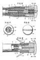
- Fig. 8 illustrates the distal end portion of another embodiment of the pacing lead of the invention.
- the pacing lead has split electrically conducting electrodes 55 and 57 which may be made of any known biocompatible electrode material, such as a platinum-iridium alloy or titanium.
- the electrodes 55 and 57 may be constructed with a solid titanium shank and an associated carbon coated porous tip made from sintered grains of titanium.
- Fig. 9 illustrates the front end portions of the split electrodes 55 and 57 as seen in the direction of the arrows 9-9 of Fig. 8. It can be seen with reference to Figs. 8 and 9 that the split electrodes 55 and 57 are supported in insulated relation by an insulating pad 59 which may be made, for example of silicone rubber or polyurethane and which is affixed in sealed relation to the electrodes 55 and 57 by any known medical adhesive such as is previously discussed.
- an insulating pad 59 which may be made, for example of silicone rubber or polyurethane and which is affixed in sealed relation to the electrodes 55 and 57 by any known medical adhesive such as is previously discussed.
- the ends of the electrically conducting coils 11 and 13 are inserted into holes drilled in the shanks of the split electrodes 55 and 57, respectively.
- the wires 11 and 13 are held in conductive connection with the split electrodes 55 and 57 by a medical adhesive or possibly by a biocompatible solder material.
- the distal end of the lead has a tine assembly 61 which may be made of a relatively flexible, biocompatible material such as silicone rubber.
- the assembly 61 is glued to the outer sheath 9 of the lead by any suitable known biocompatible medical adhesive.
- tines 63 hold the electrodes 55 and 57 against cardiac tissue 43 by intermeshing with adjacent tissue of the heart.
- the electrode of Fig. 8 senses atrial signals of the tissue 43 between the closely spaced split electrodes 55 and 57.
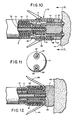
- Fig. 10 illustrates a cross-sectional view of the distal end portion of another embodiment of the pacing lead of the invention.
- the lead of Fig. 10 has three electrodes at its distal end. The first of these electrodes 17 is employed to pace the cardiac tissue 43 with respect to a ground provided by either the conducting housing of the pacer 1 or either or both of associated sensing electrodes 65 and 67.
- the sensing electrodes 65 and 67 are respectively conductively connected by crimp sleeves 69 and 71 to associated electrically conducting coils 73 and 75.
- the coils 73 and 75 are separated by an insulating sleeve 77 which may be made of polyurethane or silicone rubber.
- the tip electrode 17 is conductively connected to an inner coil 79 by crimping a sleeve portion 81 of the electrode 17 against the coil 79 and an associated stake 83 which may be made of a relatively rigid material, such as titanium or stainless steel.
- the lead of Fig. 10 also includes a tine assembly 61 which is affixed to the outer sheath 9 of the lead body by medical adhesive.
- the sensing electrodes 65 and 67 are constructed in the manner generally described for the electrode 19 of Fig. 4. Each of the electrodes 65 and 67 are held in insulated relation with respect to the tip electrode 17 by insulating sleeves 85 and 87 which may be made of, for example silicone rubber. Alternatively, the electrodes may be potted within the electrode 17 by a suitable insulating medical adhesive such as Medical Adhesive Type A.
- Fig. 11 shows an end elevation of the tip of the electrode of Fig. 10 as viewed in the direction of the arrows 11-11.
- the electrodes 67 and 65 and the tip electrode 17 abut cardiac tissue 43 to stimulate and sense the tissue.
- the electrode 17 is employed to stimulate the cardiac tissue 43 and the electrodes 65 and 67 are employed to detect electrical signals of the tissue.
- the three-wire system of the lead of Fig. 10 is thus used to stimulate the heart with the large electrode 17 and to sense atrial signals with enhanced sensitivity between the electrodes 67 and 65.
- Fig. 12 illustrates an alternative embodiment of the pacing lead of the invention which employs an electrically conducting tine assembly 89 as an electrode of the pacing lead.
- the tine assembly 89 is mounted in insulated relation with the tip electrode 17 by an insulating sleeve 91 which may be made of, for example polyurethane or silicone rubber.
- the tip electrode 17 is crimped to the inner conducting coil 13 against a titanium or stainless steel stake 88 in the manner previously described.
- the conducting tine assembly 89 is conductively connected to the outer coil 11 by an electrically conductive crimped sleeve 93, made of for example titanium or stainless steel.
- the tine assembly 89 may be made of a biocompatible metal, for example titanium or a conducting elastomer, for example silicone rubber impregnated with carbon. It is theorized that the projecting tines of the conducting tine assembly 89 will engage cardiac tissue adjacent to the tissue contacted by the electrode 17 and will therefore be sufficiently close to the electrode 17 to provide enhanced detection of atrial cardiac signals.
- Fig. 13 illustrates a cross-sectional view of the distal end portion of another alternative embodiment of the lead of the invention.
- intermeshed conductive coils 95 and 97 are used for the body of the lead.
- the coils are independently insulated so that they do not short against one another within the lead.
- a first coil 95 made of, for example, a nickel-cobalt alloy is intermeshed with a second metal coil 97 of the same material.
- Each of the coils is covered with an insulating layer which is preferably an extruded coating of polyurethane.
- the coil 95 is conductively connected to the shank of the tip electrode 17 by crimping the coil against a stake 4 made of titanium or stainless steel.
- the crimps 39 cut through the insulation of the coil to provide a good electrical connection between the coil and the electrode 17.
- the coil 97 is conductively connected to the inner electrode 19 of the lead by removing the insulation from the end of the coil and crimping this end to the end of the inner electrode in the manner described for the embodiment of Figs. 1-5.
- the advantage of the electrode of Fig. 13 is that the intermeshed bifilar coils provide a flexible lead body which has a relatively small diameter.
- sensing electrodes any desired number of sensing electrodes may be used, so long as at least two of the electrodes contact tissue, for example atrial tissue, to detect near field signals.
- sensing electrodes may be placed on different lead bodies or on different portions of a single lead body, so long as at least two sensing electrodes simultaneously contact tissue in a desired area to detect near field signals.
Landscapes
- Health & Medical Sciences (AREA)
- Heart & Thoracic Surgery (AREA)
- Vascular Medicine (AREA)
- Cardiology (AREA)
- Engineering & Computer Science (AREA)
- Biomedical Technology (AREA)
- Nuclear Medicine, Radiotherapy & Molecular Imaging (AREA)
- Radiology & Medical Imaging (AREA)
- Life Sciences & Earth Sciences (AREA)
- Animal Behavior & Ethology (AREA)
- General Health & Medical Sciences (AREA)
- Public Health (AREA)
- Veterinary Medicine (AREA)
- Electrotherapy Devices (AREA)
Claims (11)
Priority Applications (1)
| Application Number | Priority Date | Filing Date | Title |
|---|---|---|---|
| AT85309233T ATE53502T1 (de) | 1985-01-16 | 1985-12-18 | Herzschrittmacher-elektrodenleitung mit erhoehter empfindlichkeit. |
Applications Claiming Priority (2)
| Application Number | Priority Date | Filing Date | Title |
|---|---|---|---|
| US692352 | 1985-01-16 | ||
| US06/692,352 US4662382A (en) | 1985-01-16 | 1985-01-16 | Pacemaker lead with enhanced sensitivity |
Publications (2)
| Publication Number | Publication Date |
|---|---|
| EP0191238A1 EP0191238A1 (fr) | 1986-08-20 |
| EP0191238B1 true EP0191238B1 (fr) | 1990-06-13 |
Family
ID=24780233
Family Applications (1)
| Application Number | Title | Priority Date | Filing Date |
|---|---|---|---|
| EP85309233A Expired - Lifetime EP0191238B1 (fr) | 1985-01-16 | 1985-12-18 | Conducteur pour stimulateur cardiaque à sensibilité élevée |
Country Status (6)
| Country | Link |
|---|---|
| US (1) | US4662382A (fr) |
| EP (1) | EP0191238B1 (fr) |
| JP (1) | JPS61164566A (fr) |
| AT (1) | ATE53502T1 (fr) |
| CA (1) | CA1265585A (fr) |
| DE (1) | DE3578130D1 (fr) |
Families Citing this family (113)
| Publication number | Priority date | Publication date | Assignee | Title |
|---|---|---|---|---|
| US4640706A (en) * | 1984-03-30 | 1987-02-03 | Ciba-Geigy Corporation | Cyclohexenonecarboxylic acid derivatives with herbicidal and plant growth regulating properties |
| US4791911A (en) * | 1986-06-02 | 1988-12-20 | Allegheny-Singer Research Institute | Method of cardiac reconstructive surgery |
| US4796643A (en) * | 1986-09-30 | 1989-01-10 | Telectronics N.V. | Medical electrode leads |
| US4784161A (en) * | 1986-11-24 | 1988-11-15 | Telectronics, N.V. | Porous pacemaker electrode tip using a porous substrate |
| FR2616072B1 (fr) * | 1987-06-04 | 1990-12-14 | Ela Medical Sa | Perfectionnements aux extremites conductrices de sondes de stimulation cardiaque |
| USD328495S (en) | 1990-04-02 | 1992-08-04 | Advanced Technology Laboratories, Inc. | Ultrasonic transducer probe |
| US5366493A (en) * | 1991-02-04 | 1994-11-22 | Case Western Reserve University | Double helix functional stimulation electrode |
| US5179962A (en) * | 1991-06-20 | 1993-01-19 | Possis Medical, Inc. | Cardiac lead with retractible fixators |
| IT1253047B (it) * | 1991-10-02 | 1995-07-10 | Xtrode Srl | Elettrodo ad ancoraggio attivo per elettrocateteri |
| EP0571797B2 (fr) * | 1992-05-25 | 2005-10-26 | St. Jude Medical AB | Appareil de stimulation cardiaque |
| EP0585553B1 (fr) * | 1992-08-14 | 1999-09-15 | Pacesetter AB | Fil d'électrode multipolaire |
| US5385578A (en) * | 1993-02-18 | 1995-01-31 | Ventritex, Inc. | Electrical connection for medical electrical stimulation electrodes |
| US5488768A (en) * | 1993-09-24 | 1996-02-06 | Ventritex, Inc. | Method of forming a defibrillation electrode connection |
| US5380320A (en) * | 1993-11-08 | 1995-01-10 | Advanced Surgical Materials, Inc. | Electrosurgical instrument having a parylene coating |
| DE4440386A1 (de) * | 1994-11-11 | 1996-05-15 | Pacesetter Ab | Elektroden für medizinische Anwendungen |
| US5522872A (en) * | 1994-12-07 | 1996-06-04 | Ventritex, Inc. | Electrode-conductor sleeve joint for cardiac lead |
| US5654030A (en) * | 1995-02-07 | 1997-08-05 | Intermedics, Inc. | Method of making implantable stimulation electrodes |
| US5683443A (en) * | 1995-02-07 | 1997-11-04 | Intermedics, Inc. | Implantable stimulation electrodes with non-native metal oxide coating mixtures |
| FR2751232B1 (fr) * | 1996-07-19 | 1998-09-25 | Ela Medical Sa | Sonde pour dispositif medical implante, notamment pour stimulateur cardiaque |
| US5796044A (en) * | 1997-02-10 | 1998-08-18 | Medtronic, Inc. | Coiled wire conductor insulation for biomedical lead |
| US6501994B1 (en) * | 1997-12-24 | 2002-12-31 | Cardiac Pacemakers, Inc. | High impedance electrode tip |
| US6152954A (en) | 1998-07-22 | 2000-11-28 | Cardiac Pacemakers, Inc. | Single pass lead having retractable, actively attached electrode for pacing and sensing |
| US6212434B1 (en) | 1998-07-22 | 2001-04-03 | Cardiac Pacemakers, Inc. | Single pass lead system |
| US5897585A (en) * | 1997-12-18 | 1999-04-27 | Medtronic, Inc. | Stretchable pacing lead |
| US6047217A (en) * | 1998-01-15 | 2000-04-04 | Intermedics Inc. | Cardiac lead with improved polymer-to-metal joint |
| US6556862B2 (en) * | 1998-03-19 | 2003-04-29 | Cardiac Pacemakers, Inc. | Method and apparatus for treating supraventricular tachyarrhythmias |
| US6246906B1 (en) | 1998-03-19 | 2001-06-12 | Cardiac Pacemakers, Inc. | System and method for treating atrial arrhythmias |
| US6256541B1 (en) | 1998-04-17 | 2001-07-03 | Cardiac Pacemakers, Inc. | Endocardial lead having defibrillation and sensing electrodes with septal anchoring |
| US6240320B1 (en) | 1998-06-05 | 2001-05-29 | Intermedics Inc. | Cardiac lead with zone insulated electrodes |
| US6134478A (en) * | 1998-06-05 | 2000-10-17 | Intermedics Inc. | Method for making cardiac leads with zone insulated electrodes |
| US6501990B1 (en) | 1999-12-23 | 2002-12-31 | Cardiac Pacemakers, Inc. | Extendable and retractable lead having a snap-fit terminal connector |
| US6463334B1 (en) | 1998-11-02 | 2002-10-08 | Cardiac Pacemakers, Inc. | Extendable and retractable lead |
| DE69921447T2 (de) | 1999-04-02 | 2005-11-24 | Sorin Biomedica Crm S.R.L., Saluggia | Ankerstruktur für implantierbare Elektroden |
| WO2001002053A1 (fr) * | 1999-07-07 | 2001-01-11 | Cardiac Pacemakers, Inc. | Ensemble electrode endocavitaire presentant des caracteristiques de fixation conductrices |
| US6408213B1 (en) * | 1999-09-29 | 2002-06-18 | Cardiac Pacemakers, Inc. | Low profile, ventricular, transvenous, epicardial defibrillation lead |
| US6847842B1 (en) | 2000-05-15 | 2005-01-25 | Cardiac Pacemakers, Inc. | Method and apparatus for reducing early recurrence of atrial fibrillation with defibrillation shock therapy |
| US6574512B1 (en) | 2000-08-28 | 2003-06-03 | Cardiac Pacemakers, Inc. | Lead system with main lead and transverse lead |
| US6684109B1 (en) * | 2000-09-13 | 2004-01-27 | Oscor Inc. | Endocardial lead |
| US6978185B2 (en) * | 2001-11-09 | 2005-12-20 | Oscor Inc. | Multifilar conductor for cardiac leads |
| US7142928B2 (en) * | 2001-12-03 | 2006-11-28 | Medtronic, Inc. | Field stimulation about a discontinuity of the myocardium to capture the heart at reduced pacing thresholds |
| US20040092806A1 (en) * | 2001-12-11 | 2004-05-13 | Sagon Stephen W | Microelectrode catheter for mapping and ablation |
| US6978178B2 (en) * | 2002-04-30 | 2005-12-20 | Medtronic, Inc. | Method and apparatus for selecting an optimal electrode configuration of a medical electrical lead having a multiple electrode array |
| EP2075014B9 (fr) | 2002-05-24 | 2012-02-01 | Angiotech International Ag | Compositions et procédés pour le revêtement d'implants médicaux |
| US7684861B2 (en) * | 2003-11-13 | 2010-03-23 | Cardiac Pacemakers, Inc. | Implantable cardiac monitor upgradeable to pacemaker or cardiac resynchronization device |
| US7299086B2 (en) * | 2004-03-05 | 2007-11-20 | Cardiac Pacemakers, Inc. | Wireless ECG in implantable devices |
| US7720550B2 (en) * | 2004-12-03 | 2010-05-18 | Medtronic, Inc. | High impedance active fixation electrode of an electrical medical lead |
| US8005544B2 (en) | 2004-12-20 | 2011-08-23 | Cardiac Pacemakers, Inc. | Endocardial pacing devices and methods useful for resynchronization and defibrillation |
| US8010191B2 (en) | 2004-12-20 | 2011-08-30 | Cardiac Pacemakers, Inc. | Systems, devices and methods for monitoring efficiency of pacing |
| US8423139B2 (en) * | 2004-12-20 | 2013-04-16 | Cardiac Pacemakers, Inc. | Methods, devices and systems for cardiac rhythm management using an electrode arrangement |
| US8290586B2 (en) | 2004-12-20 | 2012-10-16 | Cardiac Pacemakers, Inc. | Methods, devices and systems for single-chamber pacing using a dual-chamber pacing device |
| US9006487B2 (en) * | 2005-06-15 | 2015-04-14 | Massachusetts Institute Of Technology | Amine-containing lipids and uses thereof |
| EP1968690A4 (fr) * | 2005-12-22 | 2009-02-18 | Mayo Foundation | Electrodes helicoidales pour une stimulation electrique et une détection intramyocardiques |
| US8126529B2 (en) | 2006-09-22 | 2012-02-28 | Advanced Neuromodulation Systems, Inc. | Methods and systems for securing electrode leads |
| US20080294229A1 (en) * | 2006-10-17 | 2008-11-27 | Friedman Paul A | Helical Electrodes for Intramyocardial Pacing and Sensing |
| US7822484B1 (en) * | 2007-04-03 | 2010-10-26 | Pacesetter, Inc. | MRI-compatible implantable lead having high impedance electrodes |
| US20090054947A1 (en) * | 2007-08-20 | 2009-02-26 | Medtronic, Inc. | Electrode configurations for directional leads |
| EP2195078B1 (fr) | 2007-08-20 | 2013-10-09 | Medtronic, Inc. | Conducteur médical implantable avec électrode polarisée |
| US8326418B2 (en) | 2007-08-20 | 2012-12-04 | Medtronic, Inc. | Evaluating therapeutic stimulation electrode configurations based on physiological responses |
| ES2646630T3 (es) | 2008-11-07 | 2017-12-14 | Massachusetts Institute Of Technology | Lipidoides aminoalcohólicos y usos de los mismos |
| US8364281B2 (en) * | 2008-11-07 | 2013-01-29 | W. L. Gore & Associates, Inc. | Implantable lead |
| US8996134B2 (en) | 2008-11-07 | 2015-03-31 | W. L. Gore & Associates, Inc. | Implantable lead |
| EP2473228B1 (fr) | 2009-09-03 | 2014-12-31 | Mayo Foundation For Medical Education And Research | Câbles de stimulation, de détection ou de défibrillateur pour implantation dans le myocarde |
| HUE042177T2 (hu) | 2009-12-01 | 2019-06-28 | Translate Bio Inc | Szteroidszármazék mRNS szállítására humán genetikai betegségekben |
| EP2609135A4 (fr) | 2010-08-26 | 2015-05-20 | Massachusetts Inst Technology | Poly(bêta-amino-alcools), leur préparation et utilisations de ceux-ci |
| US9238716B2 (en) | 2011-03-28 | 2016-01-19 | Massachusetts Institute Of Technology | Conjugated lipomers and uses thereof |
| PL3586861T3 (pl) | 2011-06-08 | 2022-05-23 | Translate Bio, Inc. | Kompozycje nanocząstek lipidowych i sposoby dostarczania mrna |
| EP3536787A1 (fr) | 2012-06-08 | 2019-09-11 | Translate Bio, Inc. | Polynucléotides résistant aux nucléases et leurs utilisations |
| PL3467108T3 (pl) | 2013-03-14 | 2024-09-30 | Translate Bio, Inc. | Sposoby oczyszczania informacyjnego rna |
| KR20210122917A (ko) | 2013-03-14 | 2021-10-12 | 샤이어 휴먼 지네틱 테라피즈 인크. | Cftr mrna 조성물 및 관련 방법 및 사용 |
| CN105164920B (zh) | 2013-03-15 | 2018-02-06 | 艾尔弗雷德·E·曼科学研究基金会 | 具有快速开启时间的电流感测多输出电流刺激器 |
| WO2014179562A1 (fr) | 2013-05-01 | 2014-11-06 | Massachusetts Institute Of Technology | Dérivés de 1,3,5-triazinane-2,4,6-trione et leurs utilisations |
| US9780596B2 (en) | 2013-07-29 | 2017-10-03 | Alfred E. Mann Foundation For Scientific Research | Microprocessor controlled class E driver |
| US10071243B2 (en) | 2013-07-31 | 2018-09-11 | Medtronic, Inc. | Fixation for implantable medical devices |
| US9393427B2 (en) | 2013-08-16 | 2016-07-19 | Cardiac Pacemakers, Inc. | Leadless cardiac pacemaker with delivery and/or retrieval features |
| CN105916544B (zh) | 2013-08-16 | 2019-11-12 | 心脏起搏器股份公司 | 无引线心脏起搏设备 |
| US9480850B2 (en) | 2013-08-16 | 2016-11-01 | Cardiac Pacemakers, Inc. | Leadless cardiac pacemaker and retrieval device |
| EP3033146B1 (fr) | 2013-08-16 | 2018-03-07 | Cardiac Pacemakers, Inc. | Dispositif d'administration destinés à des dispositifs cardiaques sans conducteur |
| WO2015023474A1 (fr) | 2013-08-16 | 2015-02-19 | Cardiac Pacemakers, Inc. | Stimulateur cardiaque sans fil et dispositif de récupération |
| US9492674B2 (en) | 2013-08-16 | 2016-11-15 | Cardiac Pacemakers, Inc. | Leadless cardiac pacemaker with delivery and/or retrieval features |
| US10722723B2 (en) | 2013-08-16 | 2020-07-28 | Cardiac Pacemakers, Inc. | Delivery devices and methods for leadless cardiac devices |
| US10842993B2 (en) | 2013-08-16 | 2020-11-24 | Cardiac Pacemakers, Inc. | Leadless cardiac pacing devices |
| EA034103B1 (ru) | 2013-10-22 | 2019-12-27 | Транслейт Био, Инк. | СПОСОБ ЛЕЧЕНИЯ ФЕНИЛКЕТОНУРИИ С ПРИМЕНЕНИЕМ мРНК |
| ES2707966T3 (es) | 2013-10-22 | 2019-04-08 | Translate Bio Inc | Terapia de ARNm para la deficiencia en síntesis de argininosuccinato |
| MX2016005238A (es) | 2013-10-22 | 2016-08-12 | Shire Human Genetic Therapies | Formulaciones de lipidos para la administracion de acido ribonucleico mensajero. |
| PT3134506T (pt) | 2014-04-25 | 2019-10-31 | Translate Bio Inc | Métodos de purificação de rna mensageiro |
| WO2015168155A1 (fr) | 2014-04-29 | 2015-11-05 | Cardiac Pacemakers, Inc. | Stimulateur cardiaque sans fil à caractéristiques permettant son extraction |
| US10080887B2 (en) | 2014-04-29 | 2018-09-25 | Cardiac Pacemakers, Inc. | Leadless cardiac pacing devices including tissue engagement verification |
| JP6557722B2 (ja) | 2014-05-30 | 2019-08-07 | シャイアー ヒューマン ジェネティック セラピーズ インコーポレイテッド | 核酸の送達のための生分解性脂質 |
| EP3160959B1 (fr) | 2014-06-24 | 2023-08-30 | Translate Bio, Inc. | Compositions enrichies stéréochimiquement pour l'administration d'acides nucléiques |
| US9840479B2 (en) | 2014-07-02 | 2017-12-12 | Massachusetts Institute Of Technology | Polyamine-fatty acid derived lipidoids and uses thereof |
| CN106999709B (zh) | 2014-08-15 | 2021-07-09 | 艾克索尼克斯股份有限公司 | 用于与可植入神经刺激器一起使用的集成肌电图临床医生程控器 |
| AU2015301489B2 (en) | 2014-08-15 | 2020-01-23 | Axonics Modulation Technologies, Inc. | External pulse generator device and associated methods for trial nerve stimulation |
| CN107073258B (zh) | 2014-08-15 | 2020-02-21 | 艾克索尼克斯调制技术股份有限公司 | 用于基于神经定位来进行神经刺激电极配置的系统和方法 |
| US9802038B2 (en) | 2014-08-15 | 2017-10-31 | Axonics Modulation Technologies, Inc. | Implantable lead affixation structure for nerve stimulation to alleviate bladder dysfunction and other indication |
| US9700731B2 (en) | 2014-08-15 | 2017-07-11 | Axonics Modulation Technologies, Inc. | Antenna and methods of use for an implantable nerve stimulator |
| WO2016025913A1 (fr) | 2014-08-15 | 2016-02-18 | Axonics Modulation Technologies, Inc. | Positionnement d'une dérivation électromyographique et titrage de la stimulation dans un système de stimulation nerveuse pour le traitement de la vessie hyperactive |
| CN107427685B (zh) | 2015-01-09 | 2021-09-21 | 艾克索尼克斯股份有限公司 | 与神经刺激充电设备一起使用的附接设备及相关联方法 |
| WO2016112398A1 (fr) | 2015-01-09 | 2016-07-14 | Axonics Modulation Technologies, Inc. | Patient distant et procédés associés d'utilisation avec un système de stimulation nerveuse |
| AU2016291554B2 (en) | 2015-07-10 | 2021-01-07 | Axonics Modulation Technologies, Inc. | Implantable nerve stimulator having internal electronics without ASIC and methods of use |
| US10099050B2 (en) | 2016-01-21 | 2018-10-16 | Medtronic, Inc. | Interventional medical devices, device systems, and fixation components thereof |
| US10463853B2 (en) | 2016-01-21 | 2019-11-05 | Medtronic, Inc. | Interventional medical systems |
| WO2017132374A1 (fr) | 2016-01-29 | 2017-08-03 | Axonics Modulation Technologies, Inc. | Procédés et systèmes pour ajustement de fréquence pour optimiser la charge d'un neurostimulateur implantable |
| AU2017218157B2 (en) | 2016-02-12 | 2022-09-29 | Axonics, Inc. | External pulse generator device and associated methods for trial nerve stimulation |
| EA201991747A1 (ru) | 2017-02-27 | 2020-06-04 | Транслейт Био, Инк. | НОВАЯ КОДОН-ОПТИМИЗИРОВАННАЯ мРНК CFTR |
| MX2019013752A (es) | 2017-05-16 | 2020-07-20 | Translate Bio Inc | Tratamiento de la fibrosis quística mediante el suministro de arnm que codifica cftr optimizado en codones. |
| JP7677791B2 (ja) | 2018-02-22 | 2025-05-15 | アクソニクス インコーポレイテッド | 試験的神経刺激のための神経刺激リードおよび使用方法 |
| CA3108544A1 (fr) | 2018-08-24 | 2020-02-27 | Translate Bio, Inc. | Procedes de purification d'arn messager |
| MX2021005969A (es) | 2018-11-21 | 2021-09-14 | Translate Bio Inc | Tratamiento de la fibrosis quística mediante el suministro de arnm que codifica cftr nebulizado. |
| US11642537B2 (en) | 2019-03-11 | 2023-05-09 | Axonics, Inc. | Charging device with off-center coil |
| US11759632B2 (en) | 2019-03-28 | 2023-09-19 | Medtronic, Inc. | Fixation components for implantable medical devices |
| WO2020242900A1 (fr) | 2019-05-24 | 2020-12-03 | Axonics Modulation Technologies, Inc. | Dispositif d'entraînement pour un programmateur de neurostimulateur et procédés associés d'utilisation avec un système de neurostimulation |
| US11439829B2 (en) | 2019-05-24 | 2022-09-13 | Axonics, Inc. | Clinician programmer methods and systems for maintaining target operating temperatures |
| US12420103B1 (en) | 2020-08-20 | 2025-09-23 | Axonics, Inc. | Neurostimulation leads with reduced current leakage |
Family Cites Families (14)
| Publication number | Priority date | Publication date | Assignee | Title |
|---|---|---|---|---|
| US3757789A (en) * | 1971-10-26 | 1973-09-11 | I Shanker | Electromedical stimulator lead connector |
| US4010755A (en) * | 1972-11-28 | 1977-03-08 | Preston Thomas A | Unipolar pacing catheter with plural distal electrodes |
| US4033357A (en) * | 1975-02-07 | 1977-07-05 | Medtronic, Inc. | Non-fibrosing cardiac electrode |
| DE2516848A1 (de) * | 1975-04-17 | 1976-10-28 | Silvester Sztasko | Transvenoese stimulationselektrode fuer herzschrittmacher |
| DE2952818A1 (de) * | 1979-12-28 | 1981-07-02 | Biotronik Meß- und Therapiegeräte GmbH & Co Ingenieurbüro Berlin, 1000 Berlin | Elektrode fuer einen implantierbaren herzschrittmacher |
| US4365639A (en) * | 1980-02-07 | 1982-12-28 | Applied Cardiac Electrophysiology | Catheter, cardiac pacemaker and method of pacing |
| DE3025955A1 (de) * | 1980-07-09 | 1982-01-21 | Forschungsgesellschaft für Biomedizinische Technik, 5100 Aachen | Ableitelektrode zur aufnahme bioelektrischer aktivitaet von behaarten koerperregionen |
| FR2490079A1 (fr) * | 1980-09-15 | 1982-03-19 | Boussac Saint Freres Bsf | Procede de fabrication de couches-culottes a jeter et couches-culottes obtenues par la mise en oeuvre de ce procede |
| DE3046667A1 (de) * | 1980-12-11 | 1982-07-22 | Peter Dr. 7850 Lörrach Osypka | Herzschrittmacher-elektrode |
| US4402328A (en) * | 1981-04-28 | 1983-09-06 | Telectronics Pty. Limited | Crista terminalis atrial electrode lead |
| US4444195A (en) * | 1981-11-02 | 1984-04-24 | Cordis Corporation | Cardiac lead having multiple ring electrodes |
| DE3230081A1 (de) * | 1982-08-13 | 1984-02-16 | Stöckert-Instrumente Apparatebau GmbH & Co Fertigungs- u. Vertriebs KG, 8000 München | Transvenoese, implantierbare herzschrittmacherelektrode |
| US4463765A (en) * | 1982-08-30 | 1984-08-07 | Cordis Corporation | Screw-in pacing lead assembly |
| US4502492A (en) * | 1983-04-28 | 1985-03-05 | Medtronic, Inc. | Low-polarization low-threshold electrode |
-
1985
- 1985-01-16 US US06/692,352 patent/US4662382A/en not_active Expired - Lifetime
- 1985-12-18 AT AT85309233T patent/ATE53502T1/de not_active IP Right Cessation
- 1985-12-18 DE DE8585309233T patent/DE3578130D1/de not_active Expired - Lifetime
- 1985-12-18 EP EP85309233A patent/EP0191238B1/fr not_active Expired - Lifetime
-
1986
- 1986-01-15 CA CA000499650A patent/CA1265585A/fr not_active Expired - Fee Related
- 1986-01-16 JP JP61007137A patent/JPS61164566A/ja active Pending
Also Published As
| Publication number | Publication date |
|---|---|
| DE3578130D1 (de) | 1990-07-19 |
| ATE53502T1 (de) | 1990-06-15 |
| US4662382A (en) | 1987-05-05 |
| JPS61164566A (ja) | 1986-07-25 |
| CA1265585A (fr) | 1990-02-06 |
| EP0191238A1 (fr) | 1986-08-20 |
Similar Documents
| Publication | Publication Date | Title |
|---|---|---|
| EP0191238B1 (fr) | Conducteur pour stimulateur cardiaque à sensibilité élevée | |
| US4892102A (en) | Cardiac pacing and/or sensing lead and method of use | |
| US6104961A (en) | Endocardial defibrillation lead with looped cable conductor | |
| US6249709B1 (en) | Endocardial defibrillation lead with multi-lumen body and axially mounted distal electrode | |
| US6259954B1 (en) | Endocardial difibrillation lead with strain-relief coil connection | |
| US4585004A (en) | Heart pacing and intracardiac electrogram monitoring system and associated method | |
| US5545201A (en) | Bipolar active fixation lead for sensing and pacing the heart | |
| US7027852B2 (en) | Lead with distal tip surface electrodes connected in parallel | |
| EP0596319B1 (fr) | Appareil de stimulation cardiaque | |
| US4387717A (en) | Pacer internal cardiac electrogram sensing system | |
| US6980866B2 (en) | Apparatus for sensing cardiac contractile function | |
| US3788329A (en) | Body implantable lead | |
| US5324326A (en) | Pressure sensing pacing lead | |
| US7383091B1 (en) | Medical electrical lead providing far-field signal attenuation | |
| US5423883A (en) | Implantable myocardial stimulation lead with sensors thereon | |
| US4532931A (en) | Pacemaker with adaptive sensing means for use with unipolar or bipolar leads | |
| US6097986A (en) | Retractable lead with mesh screen | |
| US20050043770A1 (en) | Multi-polar electrical medical lead connector system | |
| US5968086A (en) | Pacing and cardioversion lead systems with shared lead conductors | |
| US20080004535A1 (en) | Implantable medical device with sensing electrodes | |
| US5948014A (en) | Implantable stimulation system having a single-pass, tripolar lead and programmable polarity | |
| US7305270B1 (en) | Cardiac pacing/sensing lead providing far-field signal rejection | |
| US20040106964A1 (en) | Implantable Medical Device with Multiple Electrode Lead and Connector with Central Fastener | |
| EP0159753A1 (fr) | Conducteur cardiaque | |
| US8521286B2 (en) | Lead-carried proximal electrode for quadripolar transthoracic impedance monitoring |
Legal Events
| Date | Code | Title | Description |
|---|---|---|---|
| PUAI | Public reference made under article 153(3) epc to a published international application that has entered the european phase |
Free format text: ORIGINAL CODE: 0009012 |
|
| AK | Designated contracting states |
Kind code of ref document: A1 Designated state(s): AT BE CH DE FR GB IT LI LU NL SE |
|
| 17P | Request for examination filed |
Effective date: 19861010 |
|
| 17Q | First examination report despatched |
Effective date: 19880202 |
|
| GRAA | (expected) grant |
Free format text: ORIGINAL CODE: 0009210 |
|
| AK | Designated contracting states |
Kind code of ref document: B1 Designated state(s): AT BE CH DE FR GB IT LI LU NL SE |
|
| PG25 | Lapsed in a contracting state [announced via postgrant information from national office to epo] |
Ref country code: SE Effective date: 19900613 Ref country code: NL Effective date: 19900613 Ref country code: IT Free format text: LAPSE BECAUSE OF FAILURE TO SUBMIT A TRANSLATION OF THE DESCRIPTION OR TO PAY THE FEE WITHIN THE PRESCRIBED TIME-LIMIT;WARNING: LAPSES OF ITALIAN PATENTS WITH EFFECTIVE DATE BEFORE 2007 MAY HAVE OCCURRED AT ANY TIME BEFORE 2007. THE CORRECT EFFECTIVE DATE MAY BE DIFFERENT FROM THE ONE RECORDED. Effective date: 19900613 Ref country code: BE Effective date: 19900613 Ref country code: AT Effective date: 19900613 |
|
| REF | Corresponds to: |
Ref document number: 53502 Country of ref document: AT Date of ref document: 19900615 Kind code of ref document: T |
|
| REF | Corresponds to: |
Ref document number: 3578130 Country of ref document: DE Date of ref document: 19900719 |
|
| ET | Fr: translation filed | ||
| NLV1 | Nl: lapsed or annulled due to failure to fulfill the requirements of art. 29p and 29m of the patents act | ||
| PGFP | Annual fee paid to national office [announced via postgrant information from national office to epo] |
Ref country code: CH Payment date: 19901120 Year of fee payment: 6 |
|
| PGFP | Annual fee paid to national office [announced via postgrant information from national office to epo] |
Ref country code: SE Payment date: 19901121 Year of fee payment: 6 |
|
| PGFP | Annual fee paid to national office [announced via postgrant information from national office to epo] |
Ref country code: LU Payment date: 19901128 Year of fee payment: 6 |
|
| PG25 | Lapsed in a contracting state [announced via postgrant information from national office to epo] |
Ref country code: LU Free format text: LAPSE BECAUSE OF NON-PAYMENT OF DUE FEES Effective date: 19901231 |
|
| EPTA | Lu: last paid annual fee | ||
| PLBE | No opposition filed within time limit |
Free format text: ORIGINAL CODE: 0009261 |
|
| STAA | Information on the status of an ep patent application or granted ep patent |
Free format text: STATUS: NO OPPOSITION FILED WITHIN TIME LIMIT |
|
| 26N | No opposition filed | ||
| PG25 | Lapsed in a contracting state [announced via postgrant information from national office to epo] |
Ref country code: LI Effective date: 19911231 Ref country code: CH Effective date: 19911231 |
|
| REG | Reference to a national code |
Ref country code: CH Ref legal event code: PL |
|
| ITTA | It: last paid annual fee | ||
| PGFP | Annual fee paid to national office [announced via postgrant information from national office to epo] |
Ref country code: FR Payment date: 20001130 Year of fee payment: 16 |
|
| PGFP | Annual fee paid to national office [announced via postgrant information from national office to epo] |
Ref country code: GB Payment date: 20001201 Year of fee payment: 16 |
|
| PGFP | Annual fee paid to national office [announced via postgrant information from national office to epo] |
Ref country code: DE Payment date: 20001211 Year of fee payment: 16 |
|
| PG25 | Lapsed in a contracting state [announced via postgrant information from national office to epo] |
Ref country code: GB Free format text: LAPSE BECAUSE OF NON-PAYMENT OF DUE FEES Effective date: 20011218 |
|
| REG | Reference to a national code |
Ref country code: GB Ref legal event code: IF02 |
|
| PG25 | Lapsed in a contracting state [announced via postgrant information from national office to epo] |
Ref country code: DE Free format text: LAPSE BECAUSE OF NON-PAYMENT OF DUE FEES Effective date: 20020702 |
|
| GBPC | Gb: european patent ceased through non-payment of renewal fee |
Effective date: 20011218 |
|
| PG25 | Lapsed in a contracting state [announced via postgrant information from national office to epo] |
Ref country code: FR Free format text: LAPSE BECAUSE OF NON-PAYMENT OF DUE FEES Effective date: 20020830 |
|
| REG | Reference to a national code |
Ref country code: FR Ref legal event code: ST |