EP0194190A1 - Vorrichtung zum Erleichtern des Aussteigens aus Skiliften mit entkuppel Klemmapparaten - Google Patents
Vorrichtung zum Erleichtern des Aussteigens aus Skiliften mit entkuppel Klemmapparaten Download PDFInfo
- Publication number
- EP0194190A1 EP0194190A1 EP86400361A EP86400361A EP0194190A1 EP 0194190 A1 EP0194190 A1 EP 0194190A1 EP 86400361 A EP86400361 A EP 86400361A EP 86400361 A EP86400361 A EP 86400361A EP 0194190 A1 EP0194190 A1 EP 0194190A1
- Authority
- EP
- European Patent Office
- Prior art keywords
- station
- cable
- lines
- skiers
- declutching
- Prior art date
- Legal status (The legal status is an assumption and is not a legal conclusion. Google has not performed a legal analysis and makes no representation as to the accuracy of the status listed.)
- Granted
Links
- 230000000295 complement effect Effects 0.000 claims 1
- 230000009347 mechanical transmission Effects 0.000 claims 1
- 230000003472 neutralizing effect Effects 0.000 claims 1
- 238000009434 installation Methods 0.000 description 4
- 230000001360 synchronised effect Effects 0.000 description 2
- 241000269800 Percidae Species 0.000 description 1
- 230000005540 biological transmission Effects 0.000 description 1
- 238000010276 construction Methods 0.000 description 1
- 230000000694 effects Effects 0.000 description 1
- 239000000463 material Substances 0.000 description 1
- 238000000034 method Methods 0.000 description 1
- 230000036651 mood Effects 0.000 description 1
- 230000002250 progressing effect Effects 0.000 description 1
- 230000000135 prohibitive effect Effects 0.000 description 1
- 230000001737 promoting effect Effects 0.000 description 1
- 239000007787 solid Substances 0.000 description 1
- 230000002747 voluntary effect Effects 0.000 description 1
- 210000000707 wrist Anatomy 0.000 description 1
Images


Classifications
-
- B—PERFORMING OPERATIONS; TRANSPORTING
- B61—RAILWAYS
- B61B—RAILWAY SYSTEMS; EQUIPMENT THEREFOR NOT OTHERWISE PROVIDED FOR
- B61B12/00—Component parts, details or accessories not provided for in groups B61B7/00 - B61B11/00
- B61B12/06—Safety devices or measures against cable fracture
-
- B—PERFORMING OPERATIONS; TRANSPORTING
- B61—RAILWAYS
- B61B—RAILWAY SYSTEMS; EQUIPMENT THEREFOR NOT OTHERWISE PROVIDED FOR
- B61B11/00—Ski lift, sleigh lift or like trackless systems with guided towing cables only
- B61B11/004—Means connecting load and cable
-
- B—PERFORMING OPERATIONS; TRANSPORTING
- B61—RAILWAYS
- B61B—RAILWAY SYSTEMS; EQUIPMENT THEREFOR NOT OTHERWISE PROVIDED FOR
- B61B12/00—Component parts, details or accessories not provided for in groups B61B7/00 - B61B11/00
- B61B12/02—Suspension of the load; Guiding means, e.g. wheels; Attaching traction cables
Definitions
- the present invention relates to ski lifts or towing towing cables of the type called disengageable clamps and relates to a device for promoting. arrival station clearing skiers.
- the tractor cable passes in the direction of ascent on pulleys with a groove of horizontal axis, carried by pylons and, at the intermediate stage of the arrival station, is returned by a pulley of vertical axis called "return pulley" to descend to the departure station on pulleys similar to those used for the ascent.
- the cable carries poles or traction lines allowing the skiers to be pulled from the departure station to the arrival station.
- the poles used are fixed to the cable by disengageable pliers, the fixed pliers being more and more often abandoned.
- Clamping of the clamps on the cable is done in a known manner automatically by cooperation of the cable with the shaped bore that has a nut forming part of the clamp and the self weight of the pole is sufficient even in the absence of a towed skier for that the clutch is effective.
- each pole is engaged at the start of each skier and the rest until his return to the departure station including after the release by the skier, involuntary uphill or voluntary at the station. arrived at the top.
- the poles follow one another at the approximate maximum rate of one every 4 s and it is hardly possible to exceed a translation speed greater than 2.5 / s due to possible and even relatively frequent incidents at the arrival station.
- the present invention aims to eliminate all these drawbacks by proposing a device which is similar in terms of its cost advantages to the "drop in the pulley" type but without presenting the dangers of accidents and stopping the installation, device disengaging the pole clamp at the right of the release area to give the skier all the time necessary for his release in optimal safety conditions.
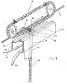
- FIG. 1 a ski lift arrival station to which the device according to the invention can be applied.
- the towing cable 1 arrives by a grooved pulley 2 routinely carried by a pylon 3 at the arrival station, to continue an approximately horizontal race up to and around the return pulley 4 before descending following a race substantially parallel to that of the climb.
- the return pulley 4 is carried by a structure 5 integral with a solid mass anchored to the ground and also carrying a carriage device cooperating with a hauling system to maintain a conve tension cable on the cable 1.
- the skier subject to his hanger 6 arrives at the end of the climb to the arrival station where a slope break and a preferably flat area are arranged to promote its release and the continuation of its course in flexibility to release the station.
- the skier permanently towed by the hanger 6 whose clamp remains constantly engaged on the cable 1 must prepare for its release from the line 6 and release it when it is already engaged in the return pulley 4, which is a delicate operation and which leaves him only a short time if he does not want to be trained when the line 6 clamp starts its circular movement around the return pulley 4.
- Figure 2 shows in side view the general constitution of a device according to the invention where we recognize the structure 5 carrying a vertical pulley with groove 2 on which arrives the cable 1 and the horizontal return pulley 4.
- the cable 1 passes to the right of a declutching station 8 of the hanger clamps, the latter being able to extend longitudinally over a distance of the order of 1 , 30 to 1.50 m, the return pulley being able to have a diameter of the order of 3.50 m.
- the construction covers a distance of the order of 5 m corresponding to the ground, to the release area of the hanger and to that of the station clearance. 'arrival.
- the declutching station 8 "for the hanger clips is shown in perspective in FIG. 3.
- a hanger 6 engaged on the cable 1 has just passed the grooved pulley 2 and entered the declutching station B.
- the hanger 6 of usual type comprises an arm 61 carrying the members represented by 62, allowing the skier to be secured in.
- This arm 61 carries in the upper part a horizontal axis 63 carrying a nut 64 by means of a nut holder arm 65.
- the nut 64 provided with a shaped bore in which the cable 1 passes passes it to give a positive clutch by the only weight of the hanger 6 therefore a fortiori when a skier is towed there.
- a known device uncouples the cable clamps, which allows the free lines to be stored and put back into service on demand by automatic clutch.
- the declutching station 8 comprises a slide 9 consisting of two longitudinal U-shaped profiles 91, 92, the lateral branches of which are arranged horizontally, leaving sufficient space between their respective ends for the free passage of the arm 61 of the hanger 6.
- the lower branches U 91, 92 carry two wings 93, 94 in the form of horns directed towards the outside constituting an entry guide for the arm 61 in the slide 9.
- the upper branches of U 91, 92 respectively carry two reported longitudinal profiles , the first round 95 cooperating with a notch of the same shape 66 formed under the nut holder arm 65, the second with square or rectangular section 96 on which the axis 63 of the nut holder comes into positive support.
- the round profile 95 and the notch 66 do not play a decisive role in the invention, the notch 66 having the function of allowing easy passage of the hanger clips 6 in line with the cheeks of the grooved pulleys 2 of the line of installation pylons.
- the invention provides for an automatic evacuation of the hangers 6 from the slide 9, up to 'at the point where they are automatically back on the cable 1, they again accompany the latter in its race around the return pulley 4 and thus descend to the departure station.
- a device for releasing the released lines 6 comprises an endless chain 101 driven by a driving toothed wheel 102 and passing towards the 'other end of the slide 9 on a second toothed wheel 103 mounted idly on its axis.
- the chain 101 carries fingers 104 projecting outwards, articulated and retractable against a return member, for example with spring, and regularly arranged on this chain 101 to correspond aqiproximatively to the frequency of arrival of the lines 6 at the declutching station 8.
- the drive of the driving wheel 102 is taken on the grooved pulley 2 located before the entry of the declutching station 8.
- This pulley 2 can be integral with a wheel 21 connected to a wheel training ment (not shown) secured to the driving wheel 102 of the chain 101, by belt or better by chain 22.
- the transmission ratios are chosen so as to obtain optimum conditions both for the flow of skiers and for their safety.
- Such a PTO linked to the movement of the cable 1 itself, therefore synchronized with it, does not require any other supply of motive energy, for example electrical, which represents a definite advantage both in terms of synchronization and on that of the energy autonomy of the device.
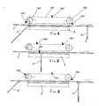
- FIG. 4 illustrate very schematically but more clearly the operation of the line release device 6 which has just been described.
- a hanger 6 has come out of the slide 9, with or without the intervention of the finger 104 ′, and a second hanger 6, still towing its skier (not shown) enters the slide 9.
- this hanger 6, disengaged from the cable 1, and already released from its skier is in the intermediate position in the slide 9 where the finger 104 catches it and pushes it towards the exit of the slide 9.
- the hanger 6 is taken out of the slide 9 and, padded on the cable 1, continues its race towards the return pulley.
- the slide 9 is free and a 6 "hanger towing its skier will present itself at the entrance to the slide 9.
- the finger 104 ' either precede it, or else take it over and, possibly, retract and c 'is then the next finger 104 "which will take over to push it out of the slide 9.
Landscapes
- Engineering & Computer Science (AREA)
- Transportation (AREA)
- Mechanical Engineering (AREA)
- Footwear And Its Accessory, Manufacturing Method And Apparatuses (AREA)
- Knives (AREA)
- Escalators And Moving Walkways (AREA)
- Studio Circuits (AREA)
Priority Applications (1)
| Application Number | Priority Date | Filing Date | Title |
|---|---|---|---|
| AT86400361T ATE39654T1 (de) | 1985-03-01 | 1986-02-19 | Vorrichtung zum erleichtern des aussteigens aus skiliften mit entkuppel klemmapparaten. |
Applications Claiming Priority (2)
| Application Number | Priority Date | Filing Date | Title |
|---|---|---|---|
| FR8503474A FR2578215B1 (fr) | 1985-03-01 | 1985-03-01 | Dispositif pour favoriser le degagement des skieurs a l'arrivee d'un teleski du type a pinces debrayables |
| FR8503474 | 1985-03-01 |
Publications (2)
| Publication Number | Publication Date |
|---|---|
| EP0194190A1 true EP0194190A1 (de) | 1986-09-10 |
| EP0194190B1 EP0194190B1 (de) | 1989-01-04 |
Family
ID=9317021
Family Applications (1)
| Application Number | Title | Priority Date | Filing Date |
|---|---|---|---|
| EP86400361A Expired EP0194190B1 (de) | 1985-03-01 | 1986-02-19 | Vorrichtung zum Erleichtern des Aussteigens aus Skiliften mit entkuppel Klemmapparaten |
Country Status (4)
| Country | Link |
|---|---|
| EP (1) | EP0194190B1 (de) |
| AT (1) | ATE39654T1 (de) |
| FR (1) | FR2578215B1 (de) |
| NO (1) | NO160838C (de) |
Cited By (1)
| Publication number | Priority date | Publication date | Assignee | Title |
|---|---|---|---|---|
| GB2305645A (en) * | 1995-10-02 | 1997-04-16 | Vincent Reginald Halsall | Overhead monorail - lowers carriage to load/unload passengers or goods |
Citations (5)
| Publication number | Priority date | Publication date | Assignee | Title |
|---|---|---|---|---|
| CH420242A (fr) * | 1964-04-15 | 1966-09-15 | Neyrpic Ateliers Neyret Beylie | Dispositif de réception en gare des véhicules de téléphériques |
| FR2094270A5 (de) * | 1970-06-15 | 1972-02-04 | Merlin Gerin | |
| AT297092B (de) * | 1967-10-23 | 1972-03-10 | Anton Wiedermann | Skilift |
| FR2390314A1 (fr) * | 1977-05-11 | 1978-12-08 | Pomagalski Sa | Teleski a attaches debrayables |
| EP0125967A1 (de) * | 1983-05-02 | 1984-11-21 | Pomagalski S.A. | Höhenverstellbare Endstation für Kabelbahnen |
-
1985
- 1985-03-01 FR FR8503474A patent/FR2578215B1/fr not_active Expired
-
1986
- 1986-02-19 EP EP86400361A patent/EP0194190B1/de not_active Expired
- 1986-02-19 AT AT86400361T patent/ATE39654T1/de not_active IP Right Cessation
- 1986-02-25 NO NO860701A patent/NO160838C/no not_active IP Right Cessation
Patent Citations (5)
| Publication number | Priority date | Publication date | Assignee | Title |
|---|---|---|---|---|
| CH420242A (fr) * | 1964-04-15 | 1966-09-15 | Neyrpic Ateliers Neyret Beylie | Dispositif de réception en gare des véhicules de téléphériques |
| AT297092B (de) * | 1967-10-23 | 1972-03-10 | Anton Wiedermann | Skilift |
| FR2094270A5 (de) * | 1970-06-15 | 1972-02-04 | Merlin Gerin | |
| FR2390314A1 (fr) * | 1977-05-11 | 1978-12-08 | Pomagalski Sa | Teleski a attaches debrayables |
| EP0125967A1 (de) * | 1983-05-02 | 1984-11-21 | Pomagalski S.A. | Höhenverstellbare Endstation für Kabelbahnen |
Cited By (1)
| Publication number | Priority date | Publication date | Assignee | Title |
|---|---|---|---|---|
| GB2305645A (en) * | 1995-10-02 | 1997-04-16 | Vincent Reginald Halsall | Overhead monorail - lowers carriage to load/unload passengers or goods |
Also Published As
| Publication number | Publication date |
|---|---|
| NO160838C (no) | 1989-06-07 |
| EP0194190B1 (de) | 1989-01-04 |
| FR2578215A1 (fr) | 1986-09-05 |
| ATE39654T1 (de) | 1989-01-15 |
| NO160838B (no) | 1989-02-27 |
| FR2578215B1 (fr) | 1987-03-06 |
| NO860701L (no) | 1986-09-02 |
Similar Documents
| Publication | Publication Date | Title |
|---|---|---|
| EP3307599B1 (de) | Vorrichtung zur kopplung eines fahrzeugs an ein zugseil, fahrzeug mit solch einer vorrichtung und zugseiltransportvorrichtung mit solch einem fahrzeug | |
| FR2539369A1 (fr) | Dispositif cadenceur pour telecabine ou telesiege debrayable | |
| FR3068423B1 (fr) | Dispositif et procede de blocage en tension d'un cable a l'aide d'une pince serre-cable | |
| EP0018932B1 (de) | Drahtseilbahn-Transportvorrichtung mit doppeltem Umlaufseil und veränderlicher Geschwindigkeit | |
| EP0263035B1 (de) | Schwebebahntransportsystem mit zwei Trage- und Zugkabeln, sowie versetzten Endstationsscheibenrädern | |
| EP0282418B1 (de) | Seilbahn mit zwei Trag- und Zugseilen sowie zwei vertikal versetzten Umlaufrädern | |
| CH626841A5 (de) | ||
| EP0194190B1 (de) | Vorrichtung zum Erleichtern des Aussteigens aus Skiliften mit entkuppel Klemmapparaten | |
| EP0863827B1 (de) | Schleppvorrichtung für skifahrer | |
| FR2614013A1 (fr) | Dispositif pour le transport de pots de filature comportant un organe de transport circulant | |
| EP2780209B1 (de) | Mechanisches hubfahrzeug | |
| FR2654052A1 (fr) | Procede pour la mise en route et l'arret d'une installation de transport aerien par cable. | |
| EP0018302A1 (de) | Sicherheitsvorrichtung für einzelne Bergsteiger und Verfahren zu ihrer Verwendung | |
| EP0423027B1 (de) | Sicherheitsanlage aktiviert von einem bewegenden Körper, insbesondere Sicherheitstor | |
| FR2557084A1 (fr) | Dispositif de main courante, notamment pour un systeme de transport tel qu'un escalier roulant ou analogue | |
| CA2240708C (fr) | Dispositif de trainage de skieurs | |
| EP1393790B1 (de) | Progressive Brems- und Anhaltevorrichtung für einen Laufwagen oder Entsprechendes | |
| EP0130897A2 (de) | Vorrichtung zum mechanischen Anheben von kleinen Fahrzeugen | |
| FR2795375A1 (fr) | Dispositif de securite pour une station d'arrivee d'une installation de convoyage | |
| CA1280383C (fr) | Teleski a perches | |
| EP1798130B1 (de) | Sicherheitsvorrichtung für eine Transportinstallation mittels Kabel | |
| FR2547568A1 (fr) | Monte-materiaux a equipage mobile deplacable verticalement et horizontalement | |
| FR2689847A1 (fr) | Pince de télésiège. | |
| EP0700816B1 (de) | Förderanlage mit zwei Schienen | |
| FR2617452A1 (fr) | Dispositif pour remonter des petits vehicules sur des pentes equipees de remonte-pentes |
Legal Events
| Date | Code | Title | Description |
|---|---|---|---|
| PUAI | Public reference made under article 153(3) epc to a published international application that has entered the european phase |
Free format text: ORIGINAL CODE: 0009012 |
|
| AK | Designated contracting states |
Kind code of ref document: A1 Designated state(s): AT CH IT LI SE |
|
| 17P | Request for examination filed |
Effective date: 19861203 |
|
| 17Q | First examination report despatched |
Effective date: 19880314 |
|
| ITF | It: translation for a ep patent filed | ||
| GRAA | (expected) grant |
Free format text: ORIGINAL CODE: 0009210 |
|
| AK | Designated contracting states |
Kind code of ref document: B1 Designated state(s): AT CH IT LI SE |
|
| REF | Corresponds to: |
Ref document number: 39654 Country of ref document: AT Date of ref document: 19890115 Kind code of ref document: T |
|
| PLBE | No opposition filed within time limit |
Free format text: ORIGINAL CODE: 0009261 |
|
| STAA | Information on the status of an ep patent application or granted ep patent |
Free format text: STATUS: NO OPPOSITION FILED WITHIN TIME LIMIT |
|
| 26N | No opposition filed | ||
| ITTA | It: last paid annual fee | ||
| REG | Reference to a national code |
Ref country code: CH Ref legal event code: PVP Owner name: CREDIT LYONNAIS SA |
|
| PGFP | Annual fee paid to national office [announced via postgrant information from national office to epo] |
Ref country code: AT Payment date: 19940214 Year of fee payment: 9 |
|
| EAL | Se: european patent in force in sweden |
Ref document number: 86400361.1 |
|
| PG25 | Lapsed in a contracting state [announced via postgrant information from national office to epo] |
Ref country code: AT Effective date: 19950219 |
|
| REG | Reference to a national code |
Ref country code: CH Ref legal event code: NV Representative=s name: BOVARD AG PATENTANWAELTE |
|
| PGFP | Annual fee paid to national office [announced via postgrant information from national office to epo] |
Ref country code: SE Payment date: 20010227 Year of fee payment: 16 |
|
| PG25 | Lapsed in a contracting state [announced via postgrant information from national office to epo] |
Ref country code: SE Free format text: LAPSE BECAUSE OF NON-PAYMENT OF DUE FEES Effective date: 20020220 |
|
| EUG | Se: european patent has lapsed |
Ref document number: 86400361.1 |
|
| PGFP | Annual fee paid to national office [announced via postgrant information from national office to epo] |
Ref country code: CH Payment date: 20040218 Year of fee payment: 19 |
|
| PG25 | Lapsed in a contracting state [announced via postgrant information from national office to epo] |
Ref country code: IT Free format text: LAPSE BECAUSE OF NON-PAYMENT OF DUE FEES;WARNING: LAPSES OF ITALIAN PATENTS WITH EFFECTIVE DATE BEFORE 2007 MAY HAVE OCCURRED AT ANY TIME BEFORE 2007. THE CORRECT EFFECTIVE DATE MAY BE DIFFERENT FROM THE ONE RECORDED. Effective date: 20050219 |
|
| PG25 | Lapsed in a contracting state [announced via postgrant information from national office to epo] |
Ref country code: LI Free format text: LAPSE BECAUSE OF NON-PAYMENT OF DUE FEES Effective date: 20050228 Ref country code: CH Free format text: LAPSE BECAUSE OF NON-PAYMENT OF DUE FEES Effective date: 20050228 |
|
| REG | Reference to a national code |
Ref country code: CH Ref legal event code: PL |