EP0194231B1 - Vorrichtung zur Belichtung diskreter Teile einer photoempfindlichen Oberfläche mittels eines Lichtstrahls - Google Patents
Vorrichtung zur Belichtung diskreter Teile einer photoempfindlichen Oberfläche mittels eines Lichtstrahls Download PDFInfo
- Publication number
- EP0194231B1 EP0194231B1 EP86810103A EP86810103A EP0194231B1 EP 0194231 B1 EP0194231 B1 EP 0194231B1 EP 86810103 A EP86810103 A EP 86810103A EP 86810103 A EP86810103 A EP 86810103A EP 0194231 B1 EP0194231 B1 EP 0194231B1
- Authority
- EP
- European Patent Office
- Prior art keywords
- disc
- objective
- lamp
- optical head
- light beam
- Prior art date
- Legal status (The legal status is an assumption and is not a legal conclusion. Google has not performed a legal analysis and makes no representation as to the accuracy of the status listed.)
- Expired - Lifetime
Links
- 230000003287 optical effect Effects 0.000 claims abstract description 48
- 230000009471 action Effects 0.000 claims description 6
- 230000007246 mechanism Effects 0.000 claims description 6
- 230000035945 sensitivity Effects 0.000 claims description 3
- 230000000694 effects Effects 0.000 claims description 2
- 239000011521 glass Substances 0.000 claims 2
- 230000004907 flux Effects 0.000 description 8
- 238000006073 displacement reaction Methods 0.000 description 5
- 239000003990 capacitor Substances 0.000 description 4
- 230000008859 change Effects 0.000 description 3
- 241001417494 Sciaenidae Species 0.000 description 2
- 239000005357 flat glass Substances 0.000 description 2
- 229910052736 halogen Inorganic materials 0.000 description 2
- 238000003754 machining Methods 0.000 description 2
- 238000004519 manufacturing process Methods 0.000 description 2
- 230000009467 reduction Effects 0.000 description 2
- 229910000831 Steel Inorganic materials 0.000 description 1
- 230000015556 catabolic process Effects 0.000 description 1
- 239000000470 constituent Substances 0.000 description 1
- 230000007547 defect Effects 0.000 description 1
- 150000002367 halogens Chemical class 0.000 description 1
- 238000005286 illumination Methods 0.000 description 1
- 230000000717 retained effect Effects 0.000 description 1
- 230000003595 spectral effect Effects 0.000 description 1
- 238000001228 spectrum Methods 0.000 description 1
- 239000010959 steel Substances 0.000 description 1
- 238000012876 topography Methods 0.000 description 1
- 238000013024 troubleshooting Methods 0.000 description 1
Images


Classifications
-
- G—PHYSICS
- G03—PHOTOGRAPHY; CINEMATOGRAPHY; ANALOGOUS TECHNIQUES USING WAVES OTHER THAN OPTICAL WAVES; ELECTROGRAPHY; HOLOGRAPHY
- G03B—APPARATUS OR ARRANGEMENTS FOR TAKING PHOTOGRAPHS OR FOR PROJECTING OR VIEWING THEM; APPARATUS OR ARRANGEMENTS EMPLOYING ANALOGOUS TECHNIQUES USING WAVES OTHER THAN OPTICAL WAVES; ACCESSORIES THEREFOR
- G03B27/00—Photographic printing apparatus
- G03B27/32—Projection printing apparatus, e.g. enlarger, copying camera
- G03B27/34—Means for automatic focusing therefor
- G03B27/36—Means for automatic focusing therefor by mechanical connections, e.g. by cam, by linkage
-
- B—PERFORMING OPERATIONS; TRANSPORTING
- B41—PRINTING; LINING MACHINES; TYPEWRITERS; STAMPS
- B41B—MACHINES OR ACCESSORIES FOR MAKING, SETTING, OR DISTRIBUTING TYPE; TYPE; PHOTOGRAPHIC OR PHOTOELECTRIC COMPOSING DEVICES
- B41B17/00—Photographic composing machines having fixed or movable character carriers and without means for composing lines prior to photography
- B41B17/04—Photographic composing machines having fixed or movable character carriers and without means for composing lines prior to photography with a carrier for all characters in at least one fount
- B41B17/06—Photographic composing machines having fixed or movable character carriers and without means for composing lines prior to photography with a carrier for all characters in at least one fount with an adjustable carrier
-
- B—PERFORMING OPERATIONS; TRANSPORTING
- B41—PRINTING; LINING MACHINES; TYPEWRITERS; STAMPS
- B41B—MACHINES OR ACCESSORIES FOR MAKING, SETTING, OR DISTRIBUTING TYPE; TYPE; PHOTOGRAPHIC OR PHOTOELECTRIC COMPOSING DEVICES
- B41B21/00—Common details of photographic composing machines of the kinds covered in groups B41B17/00 and B41B19/00
- B41B21/16—Optical systems
- B41B21/18—Optical systems defining a single optical path
- B41B21/22—Optical systems defining a single optical path with means for moving continuously
Definitions
- the invention relates to a device for exposing discrete parts of a photosensitive surface by means of a light beam, comprising a support arranged to support the photosensitive surface, an optical head making it possible to direct and adjust the light beam coming from of a lamp through symbols represented by masks distributed on a rotating disc towards the sensitive surface and means for mounting and moving the optical head and / or the sensitive surface.
- Devices for exposing discrete or selected parts of a photosensitive surface by means of a beam of light are generally used in architecture, in cartography, in topography, etc. These devices currently make it possible to carry out plans in the areas mentioned above using information and data listed in a computer. In addition to the areas mentioned above, these devices are also used to make plans of machine parts in mechanics from coded information contained in a computer. An important and well known use to date consists in using these devices for the production of printed circuits. They respond to the name of phototracer. Known phototracers usually present a numerically controlled drawing machine in which a relative movement between the drawing support and a drawing tool is produced according to an X - Y coordinate system.
- the displacements of the drawing tool are generated in a way automatic from orders, i.e. data from, for example, a computer.
- the drawing tool is usually a bright drawing head that mounts on the machine.
- the support of the design is then a photosensitive surface, on which a beam of light is projected. This beam of light can pass through symbols, which are then projected when the drawing machine stops, while the lines are projected during the movements of the light head relative to the sensitive surface.
- the choice of symbols and line widths as well as the control of the illumination of the light beam are automatic.
- British Patent No. 1,107,981 describes a device for automatically drawing a line as a function of recorded data, this device comprising two carriages or moving parts relative to each other which are driven in X and Y directions by two actuators based on the data recorded.
- Mobile crews support a light source to project a light brush onto a photosensitive surface.
- the apparatus also includes an aperture diaphragm with adjustable opening to act on the dimensions of the image of the light beam and a prism for rotating the image around an axis included in the path of the light beam, which allows an image projected to be maintained in a preferred orientation relative to the direction of the layout.
- French Patent No. 2,061,081 describes an apparatus for the automatic drawing of lines as a function of recorded data comprising the coordinates of the points of the lines to be drawn expressed with respect to reference axes.
- This device is intended for use in the field of cartography. It comprises a light source, means for projecting a beam of light onto a photosensitive surface, a diaphragm with adjustable aperture situated in the path of the light beam to act on the dimensions of the image. It also includes variable mobile means depending on the data for automatically moving the said beam and producing a trace of a line to be drawn on the photosensitive surface and means for maintaining the exposure of said trace on the surface at a predetermined value. photosensitive.
- This printing device includes, among other things, a mask-carrying disk that can be moved parallel to the light beam, to allow automatic focusing.
- All these devices generally include relatively complicated optical heads with diaphragms, numerous films, prisms or mirrors for deflecting the light beam and devices for adjusting the intensity, sharpness, etc. which make the operation of the heads insecure and especially not very fast.
- the boxes of these known devices consist of components which are firmly fixed to each other without being hinged.
- the object of the invention is to eliminate these drawbacks and to propose an optical head which is capable of working with speed and precision and whose rotating disc fitted with said masks can be replaced without any difficulty.
- This object is achieved on the basis of a device for exposing discrete parts of a surface photosensitive disposed on a support to a beam of light coming from a lamp according to the positioning of a shutter through symbols represented by masks distributed on a rotating disc provided with positioning means, as well as a lens placed between the disc carrying the masks and the sensitive surface, the objective being arranged so as to be able to move between two limits along the path of the light beam, and the disc carrying the masks being arranged so that it can also be moved between two limits parallel to the light beam, a mechanism being provided to effect relative movement of the disc and the lens.
- This device is characterized in that the objective, the device for positioning the disc, the movement mechanism and the disc are arranged in a frame machined with precision and secured to a support, and in that the lamp, the shutter and its drive means are placed in a separate block connected to the support by a hinge, said disc being arranged in such a way that it is accessible between said frame and said block so that it can be removed and replaced from the frame when said block is moved away from the frame by rotation on said hinge.
- the mechanism may include a cam controlled by the movement of the objective, the cam pushing the axis of the disc against the action of a spring and thus moving the disc according to an algorithm defining the relative movement between the disc and the objective.
- the displacement of the objective placed between the disc and the sensitive surface can be achieved by means of a screw turning in a nut plate holding the objective and controlled by a stepping motor, the nut plate carrying a pin on which rests on the surface of the machined cam so as to obey the algorithm for adjusting the position of the rotating disc.
- the objective and the disc can be controlled by stepping motors and the algorithm can be programmed in a microprocessor
- the rotary disc carrying the masks representing the symbols can be controlled by a stepping motor, the disc having a succession of notches regularly spaced on its periphery, each notch being placed opposite a corresponding bore in which a mask is placed appearing a symbol, the disc being, after rotation, locked in a predetermined position corresponding to the choice of a symbol by a pin pushed into the notch by means of a cam energized by a spring, the cam being connected to an eccentric controlled by a stepper motor.
- a shutter in the form of a strip can be placed directly after the lamp, the shutter being controlled by a stepping motor.
- a photocell can be placed adjacent to the lamp and deliver a reference voltage used to control the brightness of the lamp.
- the axis of the disc is threaded into a bore of the frame to come into contact with a cam controlled by the objective, the drive of the disc being produced by an eccentric pin entering a bore of the disc and mounted on a wheel driven by a stepping motor, the wheel and the motor being placed in the lamp unit and the disc and its axis being pressed against the lens cam by a central rod placed under the action of a spring and also arranged in the lamp unit.
- the objective can be a simple objective of the enlarger type.
- the optical head is made so as to fit into a cube with a side of 14 cm and the length of the light beam between the lamp and the sensitive surface does not exceed 10.5 cm.
- this beam is a straight beam without change of direction.
- the sensitive surface can be arranged on a rotary drum, the optical head being mounted adjacent to the drum and arranged to move along a generator of the drum.
- the sensitive surface can be arranged on a plane, the optical head being arranged to move parallel to this plane in two directions X, Y.
- the sensitive surface can be arranged on a plane, the optical head being arranged to move adjacent to the plane allowing positioning in the X axis, the table being able to move perpendicularly allowing positioning along the Y axis.
- the drawing shows, by way of example, an embodiment of the device, object of the invention.
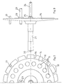
- the device shown in fig. 1 of the drawing comprises an optical head 1 schematically representing all the elements constituting the head and to the right of the drawing a drum 2 on the mantle of which is disposed a sensitive surface 3, that is to say a film of photosensitive film.
- the optical head 1 has an optical axis 4 which will cut the axis of the cylinder 2 carrying the photosensitive film.
- the cylinder 2 is mounted in a frame of the device not shown so as to be able to rotate around its axis.
- the drum 2 will be controlled by a suitable device enabling it to rotate and stop it at a predetermined location.
- the optical head 1 is mounted on a device making it possible to move it along the generatrix 5 of the mantle of the cylinder 2. This movement will be carried out using a suitable device not shown, which will move the head forward or backward along this generator 5 and which can stop this head at a predetermined location.
- the optical head 1 comprises, arranged on the optical axis 4, an incandescent lamp 6 which will serve as a light source for the optical head 1.
- This incandescent lamp is a tungsten-halogen lamp and its intensity will be adapted so as to correctly sensitize film 3, depending on the symbols to be chosen.
- To the left of the lamp 6 on the axis 4 are placed filters 7 and a photoelectric cell 8.
- the cell 8 is arranged to measure and control a luminous flux of the lamp 6 at a set value, the set value depends on the increase in the symbols to be projected, the speed of movement of the cell 1 relative to the drum 2, the speed of rotation of the drum, the sensitivity of the film, etc.
- the filters 7 are arranged to adapt the spectral sensitivity of the cell 8 to that of the film 3.
- the cell 8 will thus deliver a reference voltage which will be used to control the supply of the lamp 6 according to the symbols to be sensitized on the film 3.
- a shutter blade 9 On the other side of the lamp 6 is placed a shutter blade 9 allowing the light flux to pass or interrupting to the right of the lamp 6.
- the shutter strip 9 is controlled by a stepping motor 10.
- two filters 11 On the optical axis 4 are then placed, following the shutter 9, two filters 11 intended to compensate for the useful wavelengths, that is to say to determine the useful light spectrum.
- Two capacitors 12 are placed after the filters 11, the capacitors serving to condense the lamp luminous flux 6 on a lens 13. Between the capacitors 12 and the lens 13 is placed a disc 14 having regularly spaced bores on its periphery 15 which will be used to receive masks defining symbols to be projected on the film 3 (see also fig. 2 and 3).
- the disc 14 has, opposite each bore 15, a corresponding V-shaped slot 16 which will serve to position the disc relative to the axis 4 by means of a pin 17.
- the pin 17 will be brought into the slot 16 by means of 'a spring rod 18 pivotally mounted on an eccentric 19, itself rotated by a stepping motor 20 (fig. 1).
- the pin 17 is thus pushed into the slot 16 by the spring rod 18 when the eccentric 19 arrives in the position shown in FIG. 1, which ensures positioning absolutely without play with a pressing force of the pin 17 in the slot which is weak and constant and which thus prevents wear of the slots 16.
- the disc 14 comprises an axis 21 (fig. 1, 2 and 3) rotatably mounted and sliding in the frame, not shown, of the optical head 1.
- the disc 14 and its axis 21 are pressed against a cam 22 by means of a spring 23 (fig. 1) and of a thrust pin 24 (fig. 3).
- the thrust axis 24 is not shown in FIG. 1, which shows the elements of the optical head only in a schematic manner.
- the detail of the thrust piece 24 which rests on a ball 25 in the center of the disc 14 is shown in detail in FIG. 3.
- the disc 14 (fig. 1) is rotated and stopped in a predetermined position according to the symbol to be projected by means of a stepping motor 26 driving through a gear a rod 27 fixed on a plate 28 secured to the axis of the stepping motor 26.
- the rod 27 enters a bore 29 provided in the disc 14 (see also fig. 2 and 3).
- the free end of the axis 21 of the disc 14 also includes a ball 30 intended to push the cam 22, as explained below.
- L lens 13 is an enlarger type lens of relatively simple design. It will serve to enlarge and reduce the magnitude of the projection of the symbols contained in the bores 15 on the sensitive surface of the film 3, this function being achieved by moving the objective 13 along the axis 4 by means of the screw 32
- the nut plate 31 comprises a pin 34 on which a surface 35 of the cam 22 is pivotally mounted about a fixed axis 36.
- the machined surface 35 of the cam 22 is produced according to an algorithm calculated so as to perform clearly on the film 3 the projection of the symbols determined by the masks retained in the bores 15 of the disc 14, when the magnification of these symbols is changed. It should be noted here that the objective 13 is calculated so that the projection of the symbols can vary, continuously, between two limits ranging from 0.5 to 1.5 times the size of the said symbols.
- the relative displacement of the disc and the objective according to the algorithm could be achieved by means of two stepping motors effecting the displacement of the objective and that of the disc.
- the stepper motors would then be controlled by a microprocessor, in which the algorithm would be programmed.
- the geometry of the lens 13 has been calculated so that the symbols which are in the form of slides are projected with clarity on the film 3 by shrinking the image in an approximate ratio of 1 to 2, and by enlarging the image (symbol) also in an approximate ratio of 1.5 to 2, this continuously.
- the projected image of each symbol can thus range from less than half the diameter of the symbol continuously up to twice the diameter of the symbol, ie a continuously adjustable ratio of 3 times.
- the objective is moved parallel to the optical axis by the screw 32 and the nut plate 31, the screw being controlled by a stepping motor 33.
- the nut 31, which drives the objective 13 carries the pin 34 which rests on the cam 22.
- the cam pushes the axis 21 of disk 14 according to the calculated algorithm.
- the spring 23 ensures that the disc is always in abutment on the cam 22.
- the position of the objective 13 which is controlled by the stepping motor 33 is defined by a control computer not shown of the tracing unit. This computer also controls all the functions performed by the optical head, that is to say the stepping motors, the choice of symbols, etc.
- the disc 14 and its axis 21 are pushed by the spring 23 against the cam 22.
- the rotation of the disc 14, allowing the choice of the symbol to be projected, is controlled by the stepping motor 26.
- the precise positioning of the disc 14 is then produced by the stepping motor 20 which blocks the disc 14 in its precise position using the pin 17 entering the slot 16.
- the optical head 1 is designed in two very distinct parts 40 and 41.
- the part 40 comprises the halogen lamp 6, the filters 7 and the photoelectric cell 8, as well as the shutter 9 and its stepping motor, the filters 11, the capacitors 12, the stepping motor 26 with its drive of the disc 14 by means of the rod 27 and the push rod 24 which will come to bear in the center of the disc 14.
- the second part 41 of the optical head 1 which is produced from the machining point of view very precisely on the mechanical level is connected to the part 40 only by a hinge 42, 43.
- the part 41 does it include the axis 21 of the disc 14, the objective 13 mounted on its nut plate 31, the screw 32 driven by the stepping motor 33, the cam 22 and the device for positioning the disc which comprises the elements 17, 18, 19 and 20.
- This design makes it possible to thermally isolate the precise mechanical part of the lamp part which gives off heat.
- This arrangement also allows the symbol carrier disc 14 to be removed without problem in order to introduce another disc by opening the optical head 1, that is to say by pivoting the block 40 around the hinges 42 and 43. During this pivoting the whole block 40 and its elements as well as the push rod 24 move away from the disc 14 which can then be removed.
- the optical head thus produced therefore has a unit 40 containing the lamp 6 which can heat and expand without disturbing the operation of the optical head.
- This part 40 is surmounted by a diffuser 53 allowing the heat from the lamp to be removed.
- Part 41 including all the precision machined elements remains at room temperature and therefore does not undergo any deformation which could affect the working precision of the optical head.
- the optical head 1 finally comprises, as shown in FIG. 1, a part 50 placed at the exit of the light beam adjacent to the drum 2 carrying the sensitive surface 3 making it possible to place in the optical beam one or the other of the flat glasses treated with anti-reflection 51 and 52.
- These flat glasses make it possible to compensate the differences in thickness of the films used.
- the optical head is mounted on a device making it possible to move it above a generator of the drum 2 on which the sensitive surface is placed.
- the optical head could be mounted fixed, while the sensitive surface would be mounted on a flat carriage capable of moving in two directions.
- optical head which has just been described fits for a preferred embodiment in a cube 14 cm in side.
- these two parts 40 and 41 can be separated from each other by turning around the hinges 42 and 43 (fig. 4), so that all the elements contained in the two parts are perfectly and easily accessible. An intervention or adjustment can therefore be carried out very easily.
Landscapes
- Physics & Mathematics (AREA)
- General Physics & Mathematics (AREA)
- Exposure And Positioning Against Photoresist Photosensitive Materials (AREA)
- Exposure Of Semiconductors, Excluding Electron Or Ion Beam Exposure (AREA)
- Preparing Plates And Mask In Photomechanical Process (AREA)
- Projection-Type Copiers In General (AREA)
Claims (16)
Priority Applications (1)
| Application Number | Priority Date | Filing Date | Title |
|---|---|---|---|
| AT86810103T ATE49533T1 (de) | 1985-03-04 | 1986-02-28 | Vorrichtung zur belichtung diskreter teile einer photoempfindlichen oberflaeche mittels eines lichtstrahls. |
Applications Claiming Priority (2)
| Application Number | Priority Date | Filing Date | Title |
|---|---|---|---|
| CH964/85A CH663483A5 (fr) | 1985-03-04 | 1985-03-04 | Dispositif pour exposer des parties discretes d'une surface photosensible au moyen d'un faisceau de lumiere. |
| CH964/85 | 1985-03-04 |
Publications (2)
| Publication Number | Publication Date |
|---|---|
| EP0194231A1 EP0194231A1 (de) | 1986-09-10 |
| EP0194231B1 true EP0194231B1 (de) | 1990-01-17 |
Family
ID=4199286
Family Applications (1)
| Application Number | Title | Priority Date | Filing Date |
|---|---|---|---|
| EP86810103A Expired - Lifetime EP0194231B1 (de) | 1985-03-04 | 1986-02-28 | Vorrichtung zur Belichtung diskreter Teile einer photoempfindlichen Oberfläche mittels eines Lichtstrahls |
Country Status (6)
| Country | Link |
|---|---|
| US (1) | US4653882A (de) |
| EP (1) | EP0194231B1 (de) |
| JP (1) | JPS61269159A (de) |
| AT (1) | ATE49533T1 (de) |
| CH (1) | CH663483A5 (de) |
| DE (1) | DE3668280D1 (de) |
Families Citing this family (2)
| Publication number | Priority date | Publication date | Assignee | Title |
|---|---|---|---|---|
| US4940641A (en) * | 1988-02-17 | 1990-07-10 | The Gerber Scientific Instrument Company | Aperture disc and method of making the same |
| FR2745902B1 (fr) * | 1996-03-07 | 1998-05-22 | Instruments Sa | Systeme de photodetection et procede associe d'analyse d'un flux lumineux |
Family Cites Families (12)
| Publication number | Priority date | Publication date | Assignee | Title |
|---|---|---|---|---|
| GB278149A (en) * | 1926-08-28 | 1927-10-06 | Colin Martin Williamson | Improvements in and relating to photographic enlarging and reducing apparatus |
| US2701991A (en) * | 1950-07-20 | 1955-02-15 | Monotype Corp Ltd | Composing apparatus for reproducing typographical and like matter by photographic means |
| GB725699A (en) * | 1952-03-05 | 1955-03-09 | Hugo Heine | Photo-typesetting device |
| US2978969A (en) * | 1957-05-28 | 1961-04-11 | Heine Hugo | Photographic type-composing apparatus |
| US3317269A (en) * | 1962-06-07 | 1967-05-02 | Goodyear Aerospace Corp | Autofocus linkage |
| US3330182A (en) * | 1965-10-01 | 1967-07-11 | Gerber Scientific Instr Co | Device for exposing discrete portions of a photosensitive surface to a variable intensity light beam |
| CH464005A (de) * | 1968-02-07 | 1968-10-15 | Conradi G Ag | Photo-elektrisches Gerät zum Schreiben von Symbolen und Zeichnen kleiner Figuren mit grosser Schreib- bzw. Zeichengeschwindigkeit für eine automatische Zeichenmaschine |
| US3537364A (en) * | 1968-11-12 | 1970-11-03 | Licentia Gmbh | Automatic drawing devices |
| US3686675A (en) * | 1970-03-19 | 1972-08-22 | Faul Coradi Inc | Apparatus and method for drawing with a spot of radiant energy |
| DE7614382U1 (de) * | 1976-05-04 | 1977-07-28 | H. Berthold Ag, 1000 Berlin | Tastaturgesteuerte fotosetzmaschine |
| CA1092872A (en) * | 1978-02-23 | 1981-01-06 | Helmut M. Zoike | Variable magnification phototypesetter using heat developing paper |
| SE449531B (sv) * | 1980-12-11 | 1987-05-04 | Gerhard Westerberg | Forfarande och anordning for kontroll av mikromasker |
-
1985
- 1985-03-04 CH CH964/85A patent/CH663483A5/fr not_active IP Right Cessation
-
1986
- 1986-02-28 EP EP86810103A patent/EP0194231B1/de not_active Expired - Lifetime
- 1986-02-28 AT AT86810103T patent/ATE49533T1/de not_active IP Right Cessation
- 1986-02-28 US US06/835,041 patent/US4653882A/en not_active Expired - Fee Related
- 1986-02-28 DE DE8686810103T patent/DE3668280D1/de not_active Expired - Fee Related
- 1986-03-04 JP JP61045473A patent/JPS61269159A/ja active Pending
Also Published As
| Publication number | Publication date |
|---|---|
| EP0194231A1 (de) | 1986-09-10 |
| DE3668280D1 (de) | 1990-02-22 |
| ATE49533T1 (de) | 1990-02-15 |
| JPS61269159A (ja) | 1986-11-28 |
| CH663483A5 (fr) | 1987-12-15 |
| US4653882A (en) | 1987-03-31 |
Similar Documents
| Publication | Publication Date | Title |
|---|---|---|
| EP0401351B1 (de) | Verfahren und vorrichtung für optische messungen | |
| FR2526555A1 (fr) | Appareil de transfert et dispositif de cadrage de masques | |
| FR2524298A1 (fr) | Appareil de chirurgie ophtalmologique a laser | |
| FR2459496A2 (fr) | Appareil photographique rapporte pour microscopes | |
| CH623654A5 (de) | ||
| FR2476864A1 (fr) | Procede et dispositif de mise au point automatique dans un systeme de projection a grandissement variable | |
| EP0156683B1 (de) | Gerät für optische Microlithografie mit lokalem Ausrichtungssystem | |
| EP0194231B1 (de) | Vorrichtung zur Belichtung diskreter Teile einer photoempfindlichen Oberfläche mittels eines Lichtstrahls | |
| EP0207814A1 (de) | Verfahren zum Positionieren der Spitze eines Schneidwerkzeuges und Vorrichtung zum Anwenden dieses Verfahrens auf einer numerisch gesteuerten Drehmaschine | |
| FR2771516A1 (fr) | Dispositif formant guide de masquage pour dispositives stereoscopiques | |
| EP0001951B1 (de) | Projektionsvorrichtung, die die Bildaufnahme eines projizierten Bildes erlaubt | |
| FR2691814A1 (fr) | Procédé et appareillage d'impression d'une image. | |
| EP0036341B1 (de) | Optisches System zur Erzeugung spezieller Effekte auf Filmen | |
| FR2499442A1 (fr) | Appareil de decoupe pour effectuer une gorge sur des verres de lunette | |
| EP0083268B1 (de) | Verfahren zur automatischen Regelung der Schärfe von auf einen Schirm projizierten Bildern und Geräte dazu | |
| FR2544091A1 (fr) | Viseur d'appareil photographique | |
| FR2472207A1 (fr) | Procede pour la reproduction d'images a partir d'un support d'images transparent sur un support photosensible et dispositif pour la mise en oeuvre de ce procede | |
| FR2504695A1 (fr) | Procede pour obtenir un effet de fondu-enchaine dans la projection de vues fixes, et dispositif pour sa mise en oeuvre | |
| FR2615293A1 (fr) | Procede et dispositif pour etablir et graver un motif lumineux | |
| WO2006013245A1 (fr) | Dispositif et procede de caracterisation d’une lentille ophtalmique | |
| CH553668A (fr) | Procede et dispositif pour impressionner a l'aide d'un faisceau lumineux une couche photosensible en vue de realiser un trace. | |
| CH275462A (fr) | Dispositif télémétrique pour appareil optique comportant un objectif devant être mis au point. | |
| FR2497582A1 (fr) | Lanterne additive manuelle pour trucas, images aeriennes de bancs-titre et tireuses optiques | |
| CH521598A (fr) | Caméra cinématographique | |
| CH362318A (fr) | Photocomposeuse |
Legal Events
| Date | Code | Title | Description |
|---|---|---|---|
| PUAI | Public reference made under article 153(3) epc to a published international application that has entered the european phase |
Free format text: ORIGINAL CODE: 0009012 |
|
| AK | Designated contracting states |
Kind code of ref document: A1 Designated state(s): AT BE DE FR GB IT LU NL SE |
|
| 17P | Request for examination filed |
Effective date: 19861203 |
|
| RAP1 | Party data changed (applicant data changed or rights of an application transferred) |
Owner name: EIE ELECTRONIC INDUSTRIAL EQUIPMENT S.A. |
|
| 17Q | First examination report despatched |
Effective date: 19880322 |
|
| GRAA | (expected) grant |
Free format text: ORIGINAL CODE: 0009210 |
|
| AK | Designated contracting states |
Kind code of ref document: B1 Designated state(s): AT BE DE FR GB IT LU NL SE |
|
| REF | Corresponds to: |
Ref document number: 49533 Country of ref document: AT Date of ref document: 19900215 Kind code of ref document: T |
|
| REF | Corresponds to: |
Ref document number: 3668280 Country of ref document: DE Date of ref document: 19900222 |
|
| GBT | Gb: translation of ep patent filed (gb section 77(6)(a)/1977) | ||
| ITF | It: translation for a ep patent filed | ||
| RAP4 | Party data changed (patent owner data changed or rights of a patent transferred) |
Owner name: EIE ELECTRONIC INDUSTRIAL EQUIPMENT S.A. |
|
| PLBE | No opposition filed within time limit |
Free format text: ORIGINAL CODE: 0009261 |
|
| STAA | Information on the status of an ep patent application or granted ep patent |
Free format text: STATUS: NO OPPOSITION FILED WITHIN TIME LIMIT |
|
| 26N | No opposition filed | ||
| PGFP | Annual fee paid to national office [announced via postgrant information from national office to epo] |
Ref country code: FR Payment date: 19920113 Year of fee payment: 7 |
|
| PGFP | Annual fee paid to national office [announced via postgrant information from national office to epo] |
Ref country code: DE Payment date: 19920115 Year of fee payment: 7 Ref country code: GB Payment date: 19920115 Year of fee payment: 7 |
|
| PGFP | Annual fee paid to national office [announced via postgrant information from national office to epo] |
Ref country code: BE Payment date: 19920124 Year of fee payment: 7 Ref country code: SE Payment date: 19920124 Year of fee payment: 7 |
|
| PGFP | Annual fee paid to national office [announced via postgrant information from national office to epo] |
Ref country code: AT Payment date: 19920130 Year of fee payment: 7 Ref country code: LU Payment date: 19920130 Year of fee payment: 7 |
|
| ITTA | It: last paid annual fee | ||
| PGFP | Annual fee paid to national office [announced via postgrant information from national office to epo] |
Ref country code: NL Payment date: 19920229 Year of fee payment: 7 |
|
| EPTA | Lu: last paid annual fee | ||
| PG25 | Lapsed in a contracting state [announced via postgrant information from national office to epo] |
Ref country code: LU Free format text: LAPSE BECAUSE OF NON-PAYMENT OF DUE FEES Effective date: 19930228 Ref country code: GB Effective date: 19930228 Ref country code: BE Effective date: 19930228 Ref country code: AT Effective date: 19930228 |
|
| PG25 | Lapsed in a contracting state [announced via postgrant information from national office to epo] |
Ref country code: SE Effective date: 19930301 |
|
| BERE | Be: lapsed |
Owner name: S.A. ELECTRONIC INDUSTRIAL EQUIPMENT EIE Effective date: 19930228 |
|
| PG25 | Lapsed in a contracting state [announced via postgrant information from national office to epo] |
Ref country code: NL Effective date: 19930901 |
|
| NLV4 | Nl: lapsed or anulled due to non-payment of the annual fee | ||
| GBPC | Gb: european patent ceased through non-payment of renewal fee |
Effective date: 19930228 |
|
| PG25 | Lapsed in a contracting state [announced via postgrant information from national office to epo] |
Ref country code: FR Effective date: 19931029 |
|
| PG25 | Lapsed in a contracting state [announced via postgrant information from national office to epo] |
Ref country code: DE Effective date: 19931103 |
|
| REG | Reference to a national code |
Ref country code: FR Ref legal event code: ST |
|
| EUG | Se: european patent has lapsed |
Ref document number: 86810103.1 Effective date: 19931008 |
|
| PG25 | Lapsed in a contracting state [announced via postgrant information from national office to epo] |
Ref country code: IT Free format text: LAPSE BECAUSE OF NON-PAYMENT OF DUE FEES;WARNING: LAPSES OF ITALIAN PATENTS WITH EFFECTIVE DATE BEFORE 2007 MAY HAVE OCCURRED AT ANY TIME BEFORE 2007. THE CORRECT EFFECTIVE DATE MAY BE DIFFERENT FROM THE ONE RECORDED. Effective date: 20050228 |