EP0195786B2 - Agencement complementaire de traitement des appels d'un systeme de commutation telephonique - Google Patents
Agencement complementaire de traitement des appels d'un systeme de commutation telephonique Download PDFInfo
- Publication number
- EP0195786B2 EP0195786B2 EP85904550A EP85904550A EP0195786B2 EP 0195786 B2 EP0195786 B2 EP 0195786B2 EP 85904550 A EP85904550 A EP 85904550A EP 85904550 A EP85904550 A EP 85904550A EP 0195786 B2 EP0195786 B2 EP 0195786B2
- Authority
- EP
- European Patent Office
- Prior art keywords
- computer
- message
- system processor
- call
- data
- Prior art date
- Legal status (The legal status is an assumption and is not a legal conclusion. Google has not performed a legal analysis and makes no representation as to the accuracy of the status listed.)
- Expired - Lifetime
Links
Images


Classifications
-
- H—ELECTRICITY
- H04—ELECTRIC COMMUNICATION TECHNIQUE
- H04M—TELEPHONIC COMMUNICATION
- H04M3/00—Automatic or semi-automatic exchanges
- H04M3/60—Semi-automatic systems, i.e. in which the numerical selection of the outgoing line is under the control of an operator
-
- H—ELECTRICITY
- H04—ELECTRIC COMMUNICATION TECHNIQUE
- H04M—TELEPHONIC COMMUNICATION
- H04M3/00—Automatic or semi-automatic exchanges
- H04M3/42—Systems providing special services or facilities to subscribers
- H04M3/487—Arrangements for providing information services, e.g. recorded voice services or time announcements
- H04M3/493—Interactive information services, e.g. directory enquiries ; Arrangements therefor, e.g. interactive voice response [IVR] systems or voice portals
- H04M3/4931—Directory assistance systems
-
- H—ELECTRICITY
- H04—ELECTRIC COMMUNICATION TECHNIQUE
- H04Q—SELECTING
- H04Q11/00—Selecting arrangements for multiplex systems
- H04Q11/04—Selecting arrangements for multiplex systems for time-division multiplexing
- H04Q11/0428—Integrated services digital network, i.e. systems for transmission of different types of digitised signals, e.g. speech, data, telecentral, television signals
Definitions
- This invention relates to a method of providing call processing service in a switching system which serves a plurality of terminal equipment each of which is connected by an associated port circuit to a switching fabric of the switching system, which switching fabric is controlled by a system processor and wherein a control signalling channel connects the system processor with the port circuits.
- Stored program controlled telephone switching systems are used to interconnect telephone station sets as well as digital terminals, personal computers and large main-frame computers.
- the telephone switching system establishes communication connections between these computer facilities in a manner analogous to voice communications connections between subscribers who are using analog telephone station sets.
- the computer facilities are connected to communication pairs of the telephone switching system by modems.
- a standard telephone station set is also connected to the communication pair and is used to originate a call to a destination computerfaci lity.
- a communication connection is established through the switching network from the originating telephone station set to the destination computer facility.
- the user then switches the modem on line and the modem converts the digital signals output by the computer facility to analog signals which are transmitted by the switching network to a modem associated with the destination computer facility.
- the destination modem converts the received analog signals to digital signals for use of the destination computer facility.
- the telephone switching system simply provides a communication path between two designated end points which, in this case, are connected to computer facilities.
- the stored program controlled telephone switching system uses computers to govern its operation.
- a system processor or a number of system processors operating in synchronization are hard-wired into the telephone switching system to control call establishment and switching network operation.
- Telephone switching systems also make frequent use of hard-wired microprocessors to perform low level time consuming tasks such as line scanning, protocol conversion, etc. thereby freeing the system processor to implement the high level call processing routines.
- German Patent Application DE-OS 1941 265 discloses two computers sharing information by being connected to a common address bus. One of the computers allocates work to the other computer by performing jump instructions in the other computer. The computers transfer all information via the common address bus.
- German Patent Application DE-OS 21 20 562 discloses an arrangement wherein an auxiliary computer is interconnected to a system computer by a special purpose data channel; whereas the control information for telephones and other subscriber terminals is transferred to and received from the system computer through a scanner via a control bus.
- the problem is solved in accordance with the invention in which the method comprising the steps of receiving a predefined service request from a requesting one of the terminal equipment, transmitting call related data associated with the service request from the system processor to a computer facility connected to one of the port circuits via the control signalling channel, and processing the service request in the computer facility.
- the adjunct call processing arrangement of this invention eliminates this separation between telephone switching system computer facilities and the customer owned switchably connectable computer facilities.
- Ageneral purpose communication interface is provided which connects the customer provided computer facilities to both the switching network and the system processor of the telephone switching system via the standard telephone switching system port circuit using a control signalling channel associated with the port circuit. This general purpose communication interface enables a customer provided computer facility to provide additional call processing capability.
- attendant services call processing subroutines and the directory assistance data base and software are provided on the computer facility.
- the telephone switching system routes all attendant- directed calls to a telephone station set and associated customer computer and transmits call related data to the computer via the control signalling channel of the standard port which interconnects the telephone station and customer computer to the telephone switching system.
- the computer performs the necessary call processing and transmits a message back to the telephone switching system via the control signalling channel to indicate the switching system operation necessary to provide the requested service.
- the telephone switching system is equipped with port circuits which provide an interface to the switching system for the terminal equipment. These port circuits transmit and receive a baseband signal on the communication leads that multiplexes voice, data and control signals.
- the telephone switching system routes the voice and data components of this signal through the switching network to other port circuits and thence to the associated terminal equipment.
- the control component of this signal is routed through a control signalling channel to the system processor of the telephone switching system.
- the terminal equipment transmit and receive only call setup information such as on/off hook, dialing, ringing, button and lamp status.
- the present invention makes use of a general purpose communication interface which provides access to this existing control signalling channel capability of the telephone switching system to establish a communication path between a computer connected to the communication leads and the system processor as well as the existing voice communication path to the switching network of the telephone switching system.
- the computer and an associated voice instrument can be connected to any communication leads in the telephone switching system via this general purpose communication interface.
- the computer can communicate directly with the system processor of the telephone switching system to thereby provide new features and services, or additional call processing capability for the telephone switching system.
- call processing subroutines and their associated data bases can reside on the computer.
- the telephone switching system then operates in cooperation with the computer to process calls by way of appropriate signals communicated between the system processor and the computer over the control signalling channel.
- the telephone switching system routes attendant-directed calls to the telephone station set served by the general purpose communication interface associated with the computer and concurrently transmits call control information to the computer over the control signalling channel.
- the "operator" at the computer receives the call on the associated telephone station set as the computer concurrently receives the appropriate attendant call related data. This enables the operator at the computer to provide, for example, a combined attendant console/directory assistance function.
- the operator enters the name of the called party into the computer and the computer uses the directory assistance data base to identify the station number of the called party.
- the computer then automatically generates a call transfer request message.
- the call transfer request message is transmitted via the control signalling channel to the system processor which activates the switching network to transfer the call.
- the computer thereby relieves the telephone switching system processor of the burden of providing this real-time intensive task and also integrates what is now two discrete functions: directory assistance and attendant services.
- This adjunct call processing arrangement provides additional flexibility to the customer since the computer can be connected to any standard set of communication leads in the telephone switching system.
- any employee at any location at any time can provide the attendant console/directory assistance function without requiring dedicated wiring as is the problem with existing attendant console arrangements in telephone switching systems.
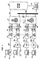
- FIG. 1 The telephone switching system of this invention is illustrated in FIG. 1.
- This system includes a plurality of terminal equipmentT11-T58 each of which is associated with a respective one of port circuits 111-158.
- This terminal equipment includes telephone station sets as well as digital terminal devices and computer facilities.
- a switching network 101 which comprises a time slot interchange circuit is connected to a number of port data/control interface circuits 171-175.
- Each port data/control interface circuit (e.g. 171) shown in FIG. 1 serves eight port circuits (111-118) and functions to interface these port circuits with switching network 101 as well as system processor 100.
- Switching network 101 operates under control of system processor 100 and establishes communication connections among the terminal equipment by interconnecting the associated port circuits 111-158.
- the standard digital terminal T11 generates an RS232 signal output which has a very limited transmission range.
- a digital terminal interface module (e.g.-DT11) is used to convert the RS232 signals output by digital terminal T11 to alternate bipolar modulated code signals which can be transmitted a significant distance over a set of communication leads TR11 to the port circuits 111 of the telephone switching system.
- the digital terminal interface module DT11 is either an integral part of the digital terminal or connected between the existing digital terminal T11 and the associated communication leads TR11.
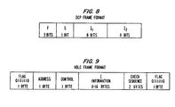
- digital terminal interface module DT11 uses a particular message frame format (DCP) to effect data transmission between port circuits such as 111 and their associated digital terminals such as T11.
- DCP message frame format
- This DCP format consists of a framing bit and three fields: an S field that conveys control signalling data, and two I fields that convey information data (FIG. 8).
- S field that conveys control signalling data
- I fields that convey information data (FIG. 8).
- one of the I fields can be used for the transmission of PCM-encoded voice information while the other one (or both I fields) can be used for the transmission of either bulk or interactive data.
- the terminal equipment served by the telephone switching system may be various types of equipment and the terminal equipment illustrated in FIG. 1 has concurrent voice and data transmission capability.
- all the terminal equipment which receive voice transmissions from the user convert the received analog voice signals into a set of digital data segments, each comprising an eight bit PCM-encoded voice sample.
- the terminal equipment which generates digital transmissions (such as keyboards) receive and originate digital data messages which are generally of length greater than eight bits.
- a typical format (HDLC) of these data messages is illustrated in FIG. 9, wherein each data message includes flag characters at the beginning and end of the data message; data, control and address fields; and a cyclic redundancy check field for error checking purposes.
- This telephone switching system is equipped with two signalling channels which reflect the basic DCP message frame format used by the port circuits.
- a control signalling channel conveys control messages (S field bits) between system processor 100 and terminal eguipment T11-T58.
- the S channel extends from each terminal (such as T11) through associated digital terminal interface module (DTIM) DT11, communication leads TR11, port circuit 111, leads P11 and thence through port data/control interface circuit 171 to system processor 100 via I/O BUS.
- the switching system is also equipped with an information channel (I channel) which conveys information data (I field segments) such as the eight-bit PCM-encoded voice signals or bulk data (in eight-bit bytes) between switching network 101 and terminal equipment T11-T58.
- the I channel extends from each terminal (such as T11) through associated digital terminal interface module (DTIM) DT11, communication leads TR11, port circuit 111, leads P11 and thence through port data/control interface circuit 171 to switching network 101 via leads PA1.
- the digital terminal and its associated digital terminal interface module multiplex the actual data transmissions (voice and data) with the control signals. This multiplexed signal is then transmitted over the communication leads to the associated port circuit where it is demultiplexed.
- the actual data transmission is switched in traditional fashion by the switching network to the designated destination and the control signals are forwarded to the system processor. Again, these control signals are the standard on-hook/off-hook status, button operation, lamp lighting, and ringing signals common to all telephone switching systems.
- System processor 100 in the course of connecting a calling digital terminal (T11) to a called digital terminal (T58), assigns a time slot in switching network 101 for the interconnection of digital terminals T11 and T58.
- Switching network 101 controls the data (I channel) transmissions between terminal equipment T11-T58.
- switching network 101 transmits each eight bit data segment received from digital terminal T58 to port circuit 111 via port data/control interface circuit 175.
- Port circuit 111 transmits each data segment so received to digital terminal T11 via digital terminal interface module (DTIM) DT11 and also receives a reply data segment from digital terminal T11 via DTIM DT11 for transmission to digital terminal T58.
- DTIM digital terminal interface module
- Port circuit 111 transmits the reply data segment received from DTIM DT11 to switching network 101 via port data/control interface circuit 171.
- Switching network 101 stores the received data segment, and interchanges the data segments received from digital terminal T11 and digital terminal T58 during the time slot assigned for this call. This action interconnects these digital terminals.
- the control or S channel transmissions are controlled by system processor 100.
- System processor 100 periodically scans each port, trunk and service circuit connected to switching network 101 to find if there is a control message for system processor 100. During each such scan cycle, system processor 100 transmits timing, address and control information to port data/control interface circuits 171-175 via I/O BUS.
- Each port data/ control interface circuit (ex. 171) has a multiplexer which interprets the signals received on I/O BUS during each scan cycle and determines whether the address signals transmitted thereon identify one of the port circuits (e.g. 111) served by that port data/control interface circuit (171). If such a match occurs during a scan cycle, port data/control interface circuit 171 enables the identified port circuit 111 to read the control message transmitted to port data/control interface circuit 171 by system processor 100.
- Port circuit 111 reads the control message written into port/data control interface circuit 171 by system processor 100 and places the control message into a control message register (not shown) in port circuit 111. Port circuit 111 transmits this control message one bit at a time from the control message register to digital terminal interface module DT11 via communication leads TR11. Digital terminal interface module DT11 assembles these serial bits into commands for digital terminal T11. Digital terminal T11 responds to these commands by performing the indicated operation, such as lighting a lamp, producing an audible ring signal, etc.
- digital terminal interface module DT11 transmits idle bits back to port circuit 111. If digital terminal T11 has a control message to send to system processor 100, it is written into the control message register of port circuit 111 one bit at a time. Port circuit 111 sets a data-ready bit in its status register (not shown) to indicate to system processor 100 that a control message has arrived from digital terminal T11. System processor 100 periodically scans the port circuit status registers via I/O BUS and port data/control circuit 171 for a set data-ready bit. When one is found, system processor 100 reads the control message stored in the control message register of port circuit 111 and resets the data-ready bit in the status register.
- the general purpose communication interface of this invention makes use of the control signalling channel (S channel) to provide a direct communication link between a computer connected to a set of communication leads and the system processor of the telephone switching system.
- the computer used for this purpose can, for example, be a personal computer having a floppy disc memory.
- the port circuit must be examined in detail. To accomplish this, a description is provided of the general purpose port circuit. This description provides an understanding of the typical digital terminal connection to the telephone switching system, upon which foundation the general purpose communication interface description can be constructed.
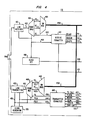
- FIGS. 4, 5 and 6, when arranged shown in FIG. 7 disclose details of the port circuit with emphasis upon the port circuitry associated with the reception and generation of S bit signalling messages in the DCP message frame format shown in FIG. 8.
- the communication leads TR18 comprises a 160 kilobit per second data link to the associated terminal equipment, computer T18.
- the 160 kilobit rate results from the fact that message segments of 20 bits (as shown in FIG. 8) are transmitted between computer T18 and port circuit 118 at an 8 Khz rate. Alternate bipolar modulation is used to transmit the data signals.
- Line receiver 401 derives its synchronization from the framing bits of each received message segment and passes the remaining fields (the S field and the two I fields) in serial form to frame demultiplexer 404 over lead 402.
- the synchronization circuitry of line receiver 401 generates a receive clock signal and applies it over lead 403 to the control portion of demultiplexer 404 as well as to receive formatter 407 and clock detector 408.
- Line receiver 401 separates the received signal from the noisy environment of the communication leads TR18 and transforms it into a logic level signal that is applied to the input of demultiplexer 404.
- Demultiplexer 404 demultiplexes the S field and the two I fields.
- the information in the two I fields comprises the data transmission from computer T18.
- This data transmission is extended over leads RI 1 and R1 2 to multiplexer 405 which multiplexes the signals together and places them on time multiplexed bus PCM.
- Each I field occupies a different time slot on time multiplexed bus PCM and thus the information in each I field is transmitted out sequentially during each occurrence of its associated time slot.
- This information is applied to the time slot interchange facilities of the system which performs a conventional time slot interchange function and interconnects each I field with the port to which the call is directed.
- This invention is not concerned with the processing or switching of the I field information and therefore it is not described herein in further detail.
- the interface from the switch multiplexer 405 to the bus PCM contains both data and clock signals to control the switch multiplexer 405 and the switch demultiplexer 448.
- the S field information comprises one bit of the message segment of FIG. 8 and is applied over lead 460 to the receive formatter407.
- Lead 460 comprises an eight ki lobit per second serial channel carrying the S field information.
- Receive formatter 407 performs the customary flag detection operation on this signal. That is, it looks for a pattern of a 0, followed by six 1 's and a 0, as shown on FIG. 9, and synchronizes to that pattern as long as the flags appear on lead 460. As soon as receive formatter 407 detects a nonflag sequence, as is the case when a signalling message character is received, it begins to perform a serial to parallel conversion on each nonflag byte.
- receiver formatter 407 performs a conventional zero delete function whenever it detects a sequence of five 1 's followed by a 0. It does this in accordance with the HDLC protocol in order to prevent a message character from being construed as the reception of a flag character.
- Receive formatter407 while it is performing this serial to parallel conversion on nonflag characters, also detects the reception of a flag character at the end of each message. It then generates a signal that is applied to lead 412 to specify the end of message for the received character. This path is also termed RCVEOM (Receive End Of Message).
- Receive formatter 407 applies each character after it is formed into a parallel format to leads 411 and from there to the receive FIFO 414. Receive formatter407 also generates a signal that is applied to lead 413 to control the strobing of information into FIFO 414. The signal on lead 413 appears concurrently with the signals on leads 411 and 412 so that they then can be strobed into FIFO 414.
- Receiver FIFO 414 is organized as a 48 word, nine bit per word FIFO.
- the nine bits in each word are the eight bits representing the received character on leads 411 and a one bit "end of message" signal on lead 412 indicating whether or not each receive character does or does not represent the last character of a message.
- the characters that are applied to the input of receive FIFO 414 pass through in the conventional manner to the output of receive FIFO 414. These eight bits are applied over leads 416 to tri-state gates 417.
- the end of message signal associated with each character is applied over lead 419 to counter 421. The end of message signal is present only when the character is indeed the last character of a message and, at that time, the end of message signal increments counter 421 by a count of one.
- Tri-state gates 417 are enabled by a read register signal on lead 420. This signal is generated by system processor 100 and applied to port circuit 118 over I/O BUS via port data/control interface circuit 171 and leads DATA when system processor 100 wishes to read the contents of FIFO 414. System processor 100 effects this operation by applying a unique address signal over the above described path to address decoder 433 to cause it to generate an output on lead 420 extending to FIFO 414 and gates 417.
- Each port circuit including port circuit 118 shown on FIGS. 4, 5 and 6, is assigned a plurality of I/O BUS addresses. The various addresses represent the various functions of which the port circuit is capable. A particular function is initiated by the application of the associated I/O BUS address to decoder 433.
- system processor 100 applies the port address associated with lead 420 to address decoder 433 via the DATA lead.
- Address decoder 433 responds to this address, drives lead 420 to cause the character at the output of FIFO 414 to be extended over leads 416 and through gates 417 to leads DATA.
- This character is then passed through port data/control interface circuit 171 and over I/O BUS to system processor 100 which stores it and every other received character until a complete message is formed.
- the read register lead 420 also extends to the OUTSTB terminal of FIFO 414.
- FIFO 414 responds to the trailing edge of this signal and advances the next character stored within FIFO 414 to the output of FIFO 414 so that it can be read on the next read registerop- eration.
- the read register signal on lead 420 performs two functions. The first is to enable gates 417 to pass the character currently on FIFO 414 output over leads 416, through gates 417 to DATA lead. The trailing edge of the read register signal on lead 420 advances the next character within FIFO 414 to the output of FIFO 414.
- the ninth bit in FIFO 414 is the END OF MESSAGE bit on lead 419.
- This signal performs two functions.
- the first function is to provide a READ END OF MESSAGE signal to the input of the Status gate 426.
- Status gate 426 can be read by system processor 100 when it performs a READ STATUS REGISTER function on port circuit 118.
- Status gate 426 has a unique address and when system processor 100 applies this address to I/O BUS, the address is decoded by decoder 433 which applies an enable signal over lead 429 to activate status gate 426.
- Status gate 426 applies the signal present on lead 419, to DATA lead for transmission to system processor 100.
- the enabling of lead 429 enables all of the status register gates 424 through 428.
- the second function of the READ END OF MESSAGE signal bit on lead 419 is to decrement R MSG counter 421.
- Counter 421 at any time has a count in it that indicates the number of messages currently stored within FIFO 414.
- Counter 421 is incremented by a RECEIVE END OF MESSAGE signal on lead 412 and is decremented when a READ END OF MESSAGE signal is read out of FIFO 414 on lead 419.
- the current count of counter 421 represents the number of complete messages currently stored within FIFO 414.
- the output of counter 421 on lead DR is the signal which permits a DATA READY indication to be read by system processor 100 as it scans status gates 424-428.
- the DR signal is extended through gate 458 when lead 422 carries an enables signal and from there the signal extends over lead 406 to the input of the scan register gate 423 and to gate 425.
- System processor 100 can read either scan register gate 423 or FIFO 414 by applying the appropriate addresses to I/O BUS. The address for either of these is decoded by decoder 433. The appropriate output of decoder 433 is enabled to activate the appropriate tristate gate, such as 423 or 417, to allow data to be applied to DATA lead.
- System processor 100 can generate and write messages into port circuit 118 of FIGS. 4, 5 and 6 for transmission to computer T18. It does this by utilizing the write portion of port circuit 118.
- the first step system processor 100 performs on a port write operation is to determine whether transmit FIFO 440 is full and is able to accept the message. If FIFO 440 is not full, system processor 100 writes the first byte of the message into port circuit 118. System processor 100 performs this function by first applying the appropriate address signal to I/O BUS. The signal that is applied is that which is associated with the write portion of port circuit 118. Decoder 433 decodes this address and generates the WREG signal on lead 435.
- This signal enables tri-state gate 434 which allows the message information now on I/O BUS to be extended through gate 434 and over lead 457 to the input of FIFO 440.
- This signal on lead 435 is also applied to the INSTB input of FIFO 440 to strobe the message information currently on lead 457 into FIFO 440.
- a WRITE END OF MESSAGE bit which is applied to FIFO 440 over lead 436.
- This signal indicates that the character associated with this bit is the last character of a transmitted message.
- System processor 100 sequentially writes each character of a message into FIFO 440. Just before the last character of the message is to be input into FIFO 440, system processor 100 writes into control register 431 via gate 432 which drives lead 459 to generate a WRITE END OF MESSAGE signal on lead 436.
- This signal is strobed into FIFO 440 at the same time the last byte of the message is strobed via the WREG signal on lead 435.
- the signal on lead 436 is automatically reset after the last byte is written into FIFO 440 by the trailing edge of the WREG signal on lead 435.
- Transmit FIFO 440 is organized as a 48 word by nine bits per word FIFO. Eight of the nine bits represent the character information; the ninth bit of each word represents the absence or presence of a WRITE END OF MESSAGE signal. Transmit FIFO 440 has a WRITE BUFFER FULL output termed WBF. When all 48 words in FIFO 440 are filled, the WBF signal is extended over lead 430 to status register gate 427. This gate is periodically read by system processor 100 prior to writing FIFO 440. When FIFO 440 is full, the output of gate 427 advises system processor 100 that FIFO 440 can accept no more bytes for the time being. If FIFO 440 is detected to be full in the middle of writing a message, system processor 100 will queue the remainder of the message and throttle the load until a previously loaded message is transmitted and FIFO 440 becomes sufficiently empty to accept at least one more byte.
- FIFO 440 receives a strobe signal from transmit formatter 445 over lead 443.
- the character information on lead 442 and the END OF MESSAGE signal on lead 441 are applied to the input of transmit formatter 445.
- Transmit formatter 445 normally continuously generates and sends out flag characters on the channel to the associated customer station as long as there are no messages in FIFO 440. At such times, transmit formatter 445 sequentially generates a flag character of 0, six 1 's and a 0. Whenever FIFO 440 is not empty, transmit formatter 445 begins the process of unloading the characters from FIFO 440 and transmitting them out over the S channel. It does this by performing a parallel to serial conversion on the received characters and the zero insertion function required for transparency.
- transmit formatter 445 first sends out flag characters when it determines from transmit FIFO 440 over lead 439 that FIFO 440 is not empty, then, at the end of transmission of the flag character, transmit formatter 445 generates a strobe signal that is applied over lead 443 to FIFO 440. This signal is used internally by transmit formatter 445 to load the character information on lead 442 and any END OF MESSAGE signal on lead 441 into transmit formatter 445. The trailing edge of this strobe signal is also used to advance FIFO 440 to bring the next character in FIFO 440 to the FIFO output.
- Transmit formatter445 performs a parallel to serial conversion on the received information. It also performs a zero insertion function when it is sending nonflag characters out over lead 446. That is, if the transmitted bit stream of the message has five consecutive 1's, transmit formatter 445 inserts a O between the fifth-1 and the next bit transmitted. Thus, transmit formatter 445 transmits out each character it receives and it checks the END OF MESSAGE bit associated with each character. When the last character in a message is received from FIFO 440, lead 441 is set to a 1. This tells transmit formatter 445 that this character is the end of a message and causes transmit formatter 445 to insert a flag after this character.
- Transmit formatter445 does this and then checks for transmit empty signal on lead 444. If the empty signal is present, transmit formatter 445 continues to generate and transmit flags. If the empty signal is not present, transmit formatter 445 then reads the next character out of FIFO 440. This new signal is a first character of a subsequent message. Transmit formatter 445 processes any such first characters of the subsequent message, and all other characters of that subsequent message, in a manner similar to that already described.
- System processor 100 can write an initialize bit into control register 431. This bit causes FIFOs 414 and 440 to be cleared as well as the MESSAGE counters 421 and 438. This effectively removes all information from port circuit 118.
- Lead 409 interconnects clock detector 408 with status register gate 424.
- Clock detector 408 normally receives clock pulses on lead 403 from line receiver 401. At such times, clock detector 408 applies a 0 over lead 409 to register gate 424. This permits system processor 100, when reading register gates 424-428, to determine that clock pulses derived from the received data stream are being received over communication pairTR18 by line receiver401 and applied over lead 403 to detector 408. This is the normal operable state of the system. If, for any reason, line receiver401 fails to receive a data stream, detector408 receives no clock pulses and sets lead 409 equal to a 1 to permit system processor 100 to read gate 424 and determine this condition. This condition could exist for example when the associated terminal equipment T18 is disconnected from communication leads TR18.
- Lead 422 interconnects the lower input of AND gate 458 with control register 431. This path is normally held in an enabled state by control register. This enables gate 458 and permits the DR output of counter 421 to be extended over lead 406 to scan register gate 423. This DATA READY signal is used to advise system processor 100 that at least a single message is currently contained within receive FIFO 414.
- Address decoder 433 contains flip-flops so that when an address is applied to the I/O BUS together with appropriate control signal by system processor 100, these control signals latch the address into the decoder flip-flops.
- the output of these flip-flops extends to circuitry which decode the address and give output signals unique to each different address.
- One of these output signals extends to lead 459. This signal is active at the time that data appears on I/O BUS and is used to strobe the data into latches in control register 431. That data is retained because it is latched into control register 431.
- Control register 431 contains flip-flops which store the state of port circuit 118 as controlled by system processor 100, as subsequently described.
- Transmit message counter438 functions similarly to receive message counter421 to indicate whether FIFO 440 currently contains a complete message. Transmit message counter 438 is incremented over lead 436 when a message is entered into FIFO 440. Transmit message counter 438 is decremented over lead 441 when a message is read out of FIFO 440.
- transmit formatter 445 extends over lead 456 to the frame multiplexer449.
- Switch demultiplexer 448 receives PCM time slot signals on bus PCM, separates out the 11 and 12 field signals for use by port circuit 118 from their assigned time slots and applies them to leads 453 and 454.
- An output of transmit message counter 438 extends to transmit formatter 445 on lead 439 which indicates when the contents of transmit message counter 438 is 0. This implies that no messages are contained in FIFO 440 and that transmit formatter 445 should generate flag characters.
- the 11, 12 signals are received by frame multi- piexer449 together with the serialized S channel bits on lead 456. Once each frame, frame multiplexer 449 inserts the eight bit 11 field, the eight bit 12 field and the one bit S field into a framing signal and applies it over lead 452 to the line transmitter 450 which adds the F field bits. From there, resultant twenty bit frame of FIG. 8 is extended over communication leads TR18 to computer T18.
- Line transmitter 450 and frame multiplexer 449 operate under control of the output signals from clock generator 455.
- Switch demultiplexer 448 receives its control signals from bus PCM.
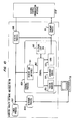
- the subject general purpose communication interface DT18 is connected to communication leads TR18 and functions to establish three communication paths between computer T18 and the telephone switching system.
- the first communication path is a voice communication channel which extends from a telephone handset 209 associated with computer T18 to the telephone switching network 101.
- the second communication path is a data communication channel which extends from a connector on the general purpose communication interface to which computer T18 is connected, to the telephone switching network 101.
- the third communication path is a signalling communication channel which extends from computer T18 to system processor 100 via the S (control signalling) channel of the telephone switching system.
- S control signalling
- I information channel
- the general purpose communication interface DT18 routes the 12 and S channel signals directly to computer T18 via a pair of RS232 connectors while the 11 channel signals are routed through CODEC 207 to a telephone handset 209 for voice communication.
- general purpose communication interface DT18 is totally transparent to messages on the S channel.
- the general purpose communication interface DT18 simply provides computer T18 with direct access to system processor 100 via the S channel.
- General purpose communication interface DT18 (illustrated in FIG. 2) is a microprocessor controlled circuit which contains a number of interface and protocol conversion devices.
- Computer T18 generates EIA control, ASCII data and timing signals that are converted by protocol conversion circuit 202 from RS232 signal levels to 5 volt logic signal levels.
- Protocol conversion circuit 202 also converts the signals received from computer T18 to a message format compatible with microprocessor 205.
- Protocol conversion circuits 202 and 204 are commercially available devices. This device is designed to interface high speed communication channels, which carry signals having an IBM Bisync or HDLC protocol, to a microcomputer.
- the protocol conversion circuit (202 and 204) interfaces two independent bi-directional serial channels from an attached device, such as computer T18 or DLI 203, to a microcomputer such as microprocessor 205.
- the serial channels between DLI 203 and protocol conversion circuit 204 carry signals having a serial protocol (HDLC).
- Protocol conversion circuit 204 decodes the serial protocol and stores the message contained therein in a receive buffer.
- Microprocessor 205 receives an interrupt when protocol conversion circuit receives valid data and reads the contents of the receive buffer. When it has messages to transmit, microprocessor 205 writes messages into a transmit buffer in protocol conversion circuit 204 for conversion to HDLC protocol and transmission to switching network 101 through DLI 203 via the serial channels.
- These messages processed by microprocessor 205 are the one bit S channel and eight bit I channel messages discussed above.
- protocol conversion circuit 202 interfaces the serial EIA RS-232C channels from computer T18 to the general purpose communication interface microprocessor 205.
- Program instructions stored in memory 206 handle the state transitions of the HDLC protocol used on the S channel and 12 channel. In fact there are two control sub-channels on the S channel: one control sub-channel corresponding to each I channel. Microprocessor 205 maintains separate protocol state information for each of these S channels (11 and 12).
- Protocol conversion circuit 204 generates idle flags when no data is being received from microcomputer 205. DLI 203 transmits these idle flags to switching network 101 via the I channel (port circuit 118, port data/control interface circuit 171) or S channel. Once computer T18 begins transmitting a data message, protocol conversion circuit 202 formats the received data message and interrupts microcomputer 205 which moves the data message in eight bit increments to a buffer in protocol conversion circuit 204. Protocol conversion circuit 204 converts the message to HDLC format and sends it to DLI 203. Protocol conversion circuit 204 calculates a CRC code on the data message to insure accuracy of transmission.
- Digital line interface 203 interconnects general purpose communication interface DT18 with port circuit 118 via communication leads TR18.
- Digital line interface 203 includes a control circuit (not shown) and a phase locked loop (not shown) which recover the clock signals from the message frames serially transmitted by port circuit 118 to general purpose communication interface DT18 via communication leads TR18. These recovered clock signals are used by digital line interface 203 to both receive message frames from port circuit 118 and generate message frames for serial transmission to port circuit 118.
- Digital line interface 203 reads out two eight bit bytes (11 and 12) at a time of the formatted data message from the data message memory of protocol conversion circuit 204. Similarly, digital line interface 203 reads one bit (S) at time of the control message stored by microprocessor 205 in protocol conversion circuit 204. Digital line interface 203 combines the two eight bit data bytes (11 and 12) with the one bit (S) control message to create the message frame of FIG. 8. The resultant message frame is transmitted in serial form by digital line interface 203 to port circuit 118 via communication leads TR18.
- Digital line interface 203 receives message frames serially transmitted by port circuit 118 on communication leads TR18. Digital line interface 203 stores the received 8 bit data bytes and control bit in protocol conversion circuit 204 via lead DS. Microprocessor 205 reads the received control message from protocol conversion circuit 204 in eight bit increments and interprets same. If the control message requires that computer T18 be signalled, microprocessor 205 loads the control message into protocol conversion circuit 202. Protocol conversion circuit 202 transmits same to computer T18.
- FIG. 3 The program instructions or software stored in memory 206 is illustrated in schematic form in FIG. 3. As shown in FIG. 3 (as boxes with round corners), there are 6 tasks performed by microprocessor 205:
- Each of the queue handler tasks and the timer task are implemented as interrupt handlers.
- the timer's (305) job is to decrement a counter for each of the S channels so the main routine can determine if there is a protocol timeout.
- the main routine (300) is an infinite loop that continuously checks for work to do. There is work to do if any of the queues that the main routine reads is non-empty. These queues are the S1 and S2 queues (309, 310) from computer T18 and the S1 and S2 queues (306, 307) from system processor 100 which contain messages that originated at computer T18 or at system processor 100, respectively.
- the job of the switch enqueue and dequeue tasks (303,304) is to send and receive S channel messages to and from system processor 100.
- the dequeue task (303) On receiving S channel message bytes from protocol converter 202, the dequeue task (303) interacts to determine when the end of the message arrives. The dequeue task (303) then reads the message itself to determine if the message arrived over the S1 channel or the S2 channel. At this point, the dequeue task (303) prepends the S channel number and the message size to the message. Additionally, microprocessor 205 adjusts the queue writer pointer to allow the main routine (300) to detect that a message is in the queue (306 or 307).
- the main routine (300) detects that one of the switch input queues (306, 307) is non-empty. Certain messages are received from the switch exclusively to satisfy the protocol. Appropriate action is taken by the main routine (300) to maintain the protocol if the message is of this type. Other messages are information messages that should be interpreted by computer T18. In this case the main routine (300) will move this message to the TO-PC queue (308) and perform whatever is necessary to satisfy the HDLC protocol used on the particular S channel. Usually this means that an acknowledge message is sent back out to system processor 100 by stuffing a message template with the proper sequence numbers and enqueueing this in the TO-SWITCH queue (311), and then resetting the timeout counter. The PC enqueue task (301) will now enqueue the message and deliver it to computer T18 via protocol converter 202.
- the PC dequeue task (302) reads messages from computer T18 via the serial port (protocol converter 202) and dequeues them in much the same way as described earlier for the switch dequeue task (304). Note that in this case there are two formats:
- An example, of the general purpose communication interface control message is to tell general purpose communication interface DT18 to transmit a TOUCH-TONE signal on the voice path. This is the mechanism by which dialing is done for voice calls.
- the message is interpreted as a command for general purpose communication interface DT18 it is executed by microprocessor 205, otherwise the message is injected into the TO-SWITCH queue (311).
- the switch enqueue task (303) wi then send it to system processor 100 over the DCP link (communication leads TR18).
- the main routine (300) also periodically checks the values of the S1 and S2 channel timeout counters S1 STATE and S2 STATE (312, 313) to determine if there is a protocol timeout. If there is, appropriate action is taken.
- General purpose communication interface DT18 thereby implements a direct communication channel between computer T18 and system processor 100.
- the signalling protocol disparity between computer T18 and system processor 100 is handled by the selection of protocol conversion devices 202, 204 while the transfer of messages between protocol conversion devices 202, 204 is orchestrated by microprocessor 205 operating under control of program instructions stored in memory 206.
- Microprocessor 205 creates the necessary message queues and coordinates the operation of protocol conversion devices 202, 204. This arrangement accomplishes the elimination of the existing barrier between customer provided computer facilities and the system processor of the telephone switching system.
- General purpose communication interface DT18 makes system processor 100 available to computer T18.
- the software resident on computer T18 can be provided by the customer to enhance existing services or provide new services for the telephone switching system. An example of such an arrangement is described in detail below.
- Computer T18 can be any general purpose computer used in the present embodiment. This computer is equipped with a standard UNIXTM operating system and the set of program instructions used to implement the subject invention are illustrated in schematic form in FIG. 10. These instructions are implemented as statements of the C programming language.
- the subject invention is the implementation of an integrated attendant console/directory assistance system on computer facility T18 which system operates cooperatively with the telephone switching system to process attendant service requests.
- Computer facility T18 performs the actual call processing required to serve the attendant service request and signals the telephone switching system to implement the actual call connection.
- the telephone switching system is relieved of the burden of processing attendant and directory assistance calls since these are handled by computer facility T18.
- the directory assistance data base is used by computerfacility T18 not only to identify the called party to the attendant but also to generate the actual call connect message for transmission to system processor 100.
- the implementation of this service is illustrated in block diagram form in FIG. 10.
- an attendant position consists of an attendant console wired into a special port appearance in the telephone switching network, a computer terminal which is hard-wired to a stand-alone computer system which provides customer directory service, and a pad and pencil for note taking. All three of these components are both physically and logically segregated.
- the attendant often has to transfer information from one of these components to another to process a request for service. For example, consider the case of an outside caller requesting to talk to an employee in the building served by the telephone switching system.
- the attendant receives the call on the attendant console and has to enter the called name via the computer terminal keyboard as a query on the customer directory service data base.
- the computer system responds to this data entry by searching the data base.
- the computer system When the computer system locates the entry corresponding to the called name, it displays the called party's name and number on the computer terminal. The attendant then has to dial that number on the console using either the TOUCH-TONE pad or the direct station select buttons. Once the called party answers, the attendant operates the appropriate buttons on the attendant console to connect calling and called parties. If the called party is busy, the attendant has to record the calling party's name, the attendant console switched loop appearance on which the calling party appears and the called party's name and number. This recorded information is later used by the attendant to complete the call when the called party goes on-hook.
- the subject attendant call processing arrangement physically and logically integrates these various functions. In most cases, the transfer of data between one logical device and another can be done automatically by software in the computer facility without requiring the attendant's intervention. This is accomplished by the use of the communication channel between computer facility T18 and system processor 100 wherein general purpose communication interface DT18 passes the signalling channel messages between system processor 100 and the call processing software which runs on computer facility T18.
- computer facility T18 can be connected via general purpose communication interface DT18 to any port circuit in the telephone switching system.
- the administration of this arrangement is obviously dependent on the structure the telephone switching system facilities management apparatus.
- Atypical facilities management arrangement (assumed to be implemented on the subject telephone switching system) requires that system processor be programmed to interface with a specified variety of terminal equipment.
- system administrator signals system processor 100 of such an interconnection via a facilities administration terminal. This operation activates service to the associated port circuit and system processor 100 can communicate with the connected terminal equipment by using the message set defined for the identified type of terminal equipment.
- system processor 100 must be programmed to communicate with this terminal equipment.
- the programming includes creating a message set which enables the terminal equipment and system processor 100 to efficiently communicate over the control signalling channel so that the terminal equipment can perform the functions for which it was designed.
- the message set associated with computer facility T18 is implemented such that computer facility T18 appears to system processor 100 like a standard multi-button electronic telephone station set terminating a DCP link from a standard port circuit.
- Computer facility T18 is programmed with the attendant call processing software which is normally located in system processor 100.
- the directory assistance data base and service software are stored on computerfacility T18.
- System processor 100 transmits call related data to computerfacility T18 on an attendant service request and receives back from computer facility T18 switching system operation signals which indicate the operation necessary to serve the received request.
- Each of these processes prepends a code to each message which identifies itself.
- the receive process (1000) reads the UNIX pipe that is associated with the serial port connected to general purpose communication interface DT18.
- the receive process (1000) interprets all signalling messages which arrive from system processor 100 and translates these signalling messages into a standard message set with a functional meaning that is used for all interprocess communication.
- the receive process (1000) can write into two pipes, one of which terminates on the transmit process (1001) and the other of which terminates on the console process (1004).
- the use of the two pipes are for the two types of messages which arrive from system processor 100: inquiry messages and command messages.
- An inquiry message is routed from the receive process (1000) to the transmit process (1001) where the transmit process (1001) generates a response for system processor 100 based on the data stored in the transmit process (1001) concerning the status of the associated keyboard and "attendant console".
- the timer process (1002) is a clock generation arrangement which periodically sends the date and time-of-day signals to the console process (1004). In addition, the timer process (1002) transmits clock signals to the console process (1004) to indicate that calls on hold should be checked to see if they can be completed.
- the keyboard process (1003) is an endless routine which scans the keyboard and reads characters from a UNIX pipe associated with the keyboard. These characters can be cursor controlled, ASCII characters, carriage return or special function sequences that represent specific actions.
- the keyboard process (1003) takes the received characters, packages them up into a message and sends the resultant message on to the console process (1004).
- the console process (1004) performs several functions and contains most of the intelligence in this particular software.
- the functions of the console process (1004) are: maintaining a data base which represents the state of the telephone (1010), managing the windows on the CRT (1013), performing the customer directory look-up (1014), and controlling the overall software activity (1014) to implement the attendant call processing function.
- the first task listed above involves creating a data base using a template of a multi-button electronic telephone station set which is used as the "pseudo attendant console" to indicate the state of the telephone associated with the attendant service.
- This data base (1010) is updated as messages from system processor 100 indicate changes in the lamp and ringer status of the telephone station set. It is through this data base that the software is able to determine which line appearances are ringing, on hold, etc.
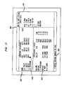
- the human interface of computer facility T18 is by way of windows which appear on the CRT screen of computer facility T18. As shown in FIG. 11, there are five windows used to implement the attendent console/directory function. These windows are: a customer directory service window (1101) for looking- up the extension of a called party, a time-of-day and date window (1102), a speed call window (1103) from which the attendant can select preprogrammed telephone numbers, a window (1104) displaying called party status, and an input window (1105).
- the display shown in FIG. 11 includes a time-of-day window (1102) which indicates the actual time as well as any error messages to the attendant.
- the directory service window (1101) is a field used for performing directory look-ups.
- the attendant would operate this particular function by moving the cursor (1106) on the CRT screen to the next available line in the directory service window (1101) and typing in the name of the called party.
- the keyboard process (1003) receives the cursor movement and keystroke signals and transmits these signals to the soft-ware in the attendant console process (1004).
- the console process (1004) accesses the directory service data base (1014) contained in the console process (1004) to obtain information as to the extension, room number and department of the called party.
- the console process (1004) transmits this data (via screen handler 1013) to the CRT which displays same to the right of the name of the called party entered by the attendant.
- a speed calling window (1103) on the CRT displays a list of frequently called names, services or locations. Calls can be forwarded from the attendent console to any of these preprogrammed numbers with a single keystroke. This is accomplished by the attendant moving the cursor (1106) on the CRT next to the desired destination indication and operating the ACTION key (not shown) on the keyboard.
- the keyboard process (1003) receives both the cursor movement and keystroke signals and transmits these signals to the console process (1004).
- the console process (1004) translates these received signals into a request for access to the particular identified destination. The telephone number of this destination is obtained from a speed call table (1010) STORED IN TELEPHONE STATE DATA, in the console process (1004).
- the console process (1004) creates a dialing message containing this number and transmits same to system processor 100 via the transmit process (1001), general purpose communication interface DT18 and the signalling channel.
- System processor 100 receives the dialing message, which is of the same format as a dialing message from a standard telephone station set, and establishes a switching network connection between the station set 209 associated with computerfacility T18 and the identified destination.
- the appearance status window (1104) displays up-to-date information about the line appearances which terminate on this attendant console.
- the columns shown on FIG. 11 are: CALLING, for calling party identification; CALLED, called party identification; EXT, for the number of the called party; STATUS, for the call status of the particular line appearance; and TIME, for the length of the time that the call has been in this particular status.
- system processor 100 When the incoming call is detected by the telephone switching system, system processor 100 generates an incoming call message which is transmitted through the communication channel, general purpose communication interface DT18, computer facility receive process (1000) to the computer facility console process (1004).
- the console process (1004) receives the message and generates a status indication for the line associated with the incoming call and changes the status indication on the CRT appearance status window from "idle" to "ringing".
- the calling party is identified as "outside” and the TIME column starts displaying the elapsed time that this incoming call has remained in the ring state.
- the console process (1004) uses the clock signals from timer process (1002) to generate a beep on the CRT each five seconds to alert the attendant. The attendant answers this call by positioning the cursor (1106) on the CRT over the ringing line appearance and operating the ACTION key on the keyboard.
- the keyboard process (1003) receives both the cursor movement and keystroke signals and transmits these signals to the console process (1004).
- the console process (1004) translates these received signals into a request for connection to the ringing line.
- the line number of the ringing line is obtained from the console process data base (1010) STORED IN TELEPHONE STATE DATA, by using the template stored therein to identify the line associated with the cursor location.
- the line number is then mapped into an appearance number.
- the console process (1004) generates an off-hook message for this appearance number which identifies the ringing line and transmits this message to system processor 100 via the transmit process (1001), general purpose communication interface DT18 and the signalling channel.
- System processor 100 responds to this standard off-hook line message by establishing a switching network connection between the calling party and the identified off-hook telephone station set.
- the attendant is now directly connected to the calling party and asks the caller for his/her name.
- the attendant moves the cursor (1106) next to this line appearance indication on the CRT and types the calling party's name over the "outside" indication that currently occupies the CALLING field.
- the attendant then asks the caller to whom the call should be placed and uses the directory service window (1101) to look-up the number of the called party. This is accomplished by the attendant moving the cursor (1106) on the CRT to the directory service window (1101) and typing the name of the called party on the terminal keyboard.
- the keyboard process (1003) receives both the cursor movement and keystroke signals and transmits these signals to the console process (1004).
- the console process (1004) translates these received signals via the stored attendant console template (1010) STORED IN TELEPHONE STATE DATA, and determines that a directory service request has been input.
- the console process (1004) uses the name of the called party to obtain the requested called party data from the directory service data base (1014).
- the console process (1004) completes the directory service window (1101) entry by displaying the extension, location, department number, and busy/idle status of the called party on the CRT screen next to the name of the called party.
- the keyboard process (1003) receives the keyboard signal and transmits this signal to the console process (1004).
- the console process (1004) recognizes the cursor location and the segu- ence of operation just described as a request to transfer the calling party to the extension identified by the directory service routine.
- the console process (1004) generates (1012) a call transfer request message and transmits (1015) same via the transmit process (1001), general purpose communication interface DT18 and the control signalling channel to system processor 100.
- System processor 100 responds to this message by transferring the identified calling party to the extension identified in this message.
Landscapes
- Engineering & Computer Science (AREA)
- Signal Processing (AREA)
- Computer Networks & Wireless Communication (AREA)
- Communication Control (AREA)
- Exchange Systems With Centralized Control (AREA)
- Data Exchanges In Wide-Area Networks (AREA)
- Interface Circuits In Exchanges (AREA)
- Use Of Switch Circuits For Exchanges And Methods Of Control Of Multiplex Exchanges (AREA)
Abstract
Claims (8)
caractérisé en ce que
caractérisé en ce que
Applications Claiming Priority (3)
| Application Number | Priority Date | Filing Date | Title |
|---|---|---|---|
| US06/654,885 US4653085A (en) | 1984-09-27 | 1984-09-27 | Telephone switching system adjunct call processing arrangement |
| US654885 | 1984-09-27 | ||
| PCT/US1985/001681 WO1986002219A1 (fr) | 1984-09-27 | 1985-09-03 | Agencement complementaire de traitement des appels d'un systeme de commutation telephonique |
Publications (3)
| Publication Number | Publication Date |
|---|---|
| EP0195786A1 EP0195786A1 (fr) | 1986-10-01 |
| EP0195786B1 EP0195786B1 (fr) | 1990-07-25 |
| EP0195786B2 true EP0195786B2 (fr) | 1994-08-31 |
Family
ID=24626629
Family Applications (1)
| Application Number | Title | Priority Date | Filing Date |
|---|---|---|---|
| EP85904550A Expired - Lifetime EP0195786B2 (fr) | 1984-09-27 | 1985-09-03 | Agencement complementaire de traitement des appels d'un systeme de commutation telephonique |
Country Status (7)
| Country | Link |
|---|---|
| US (1) | US4653085A (fr) |
| EP (1) | EP0195786B2 (fr) |
| JP (1) | JP2701838B2 (fr) |
| KR (1) | KR930010298B1 (fr) |
| CA (1) | CA1237805A (fr) |
| DE (1) | DE3578903D1 (fr) |
| WO (1) | WO1986002219A1 (fr) |
Families Citing this family (58)
| Publication number | Priority date | Publication date | Assignee | Title |
|---|---|---|---|---|
| EP0207255B1 (fr) * | 1985-07-05 | 1991-01-16 | Siemens-Albis Aktiengesellschaft | Montage pour commander et maintenir un central de télécommunications, en particulier un central téléphonique |
| US4727575A (en) * | 1985-12-23 | 1988-02-23 | American Telephone And Telegraph Company, At&T Bell Laboratories | State control for a real-time system utilizing a nonprocedural language |
| US4747127A (en) * | 1985-12-23 | 1988-05-24 | American Telephone And Telegraph Company, At&T Bell Laboratories | Customer programmable real-time system |
| US4763353A (en) * | 1986-02-14 | 1988-08-09 | American Telephone And Telegraph Company | Terminal based adjunct call manager for a communication system |
| US4748656A (en) * | 1986-03-21 | 1988-05-31 | American Telephone And Telegraph Company | Personal computer--as an interface between a telephone station set and a business communication system |
| US4734931A (en) * | 1986-03-21 | 1988-03-29 | American Telephone And Telegraph Company And At&T Information Systems Inc. | Integrated calling directory |
| US4817130A (en) * | 1986-09-11 | 1989-03-28 | International Telesystems Corporation | Call management system with protocol converter and port controller |
| JPH02500073A (ja) * | 1986-10-08 | 1990-01-11 | アメリカン テレフォン アンド テレグラフ カムパニー | 電話帳問合せ呼処理と非管理信号監視装置 |
| US4959855A (en) * | 1986-10-08 | 1990-09-25 | At&T Bell Laboratories | Directory assistance call processing and calling customer remote signal monitoring arrangements |
| DE3729133C1 (de) * | 1987-09-01 | 1989-03-16 | Telefonbau & Normalzeit Gmbh | Schaltungsanordnung fuer den Betrieb von Bedien- oder Abfrageplaetzen an zentral gesteuerten Fernsprechvermittlungsanlagen,insbesondere Makler-Vielfachanlagen |
| US4845722A (en) * | 1987-10-16 | 1989-07-04 | Digital Equipment Corporation | Computer interconnect coupler employing crossbar switching |
| US4887076A (en) * | 1987-10-16 | 1989-12-12 | Digital Equipment Corporation | Computer interconnect coupler for clusters of data processing devices |
| US4878240A (en) * | 1988-01-25 | 1989-10-31 | Bell Communications Research, Inc. | Multi-service telephone switching system |
| CA1314965C (fr) * | 1988-03-01 | 1993-03-23 | Gerald Molnar | Interface de donnees pour systeme telephonique |
| US4894824A (en) * | 1988-03-31 | 1990-01-16 | American Telephone And Telegraph Company, At&T Bell Laboratories | Control network for a rapid connection circuit switch |
| US5023868A (en) * | 1988-12-29 | 1991-06-11 | At&T Bell Laboratories | Automated call handling apparatus |
| US5062103A (en) * | 1988-12-29 | 1991-10-29 | At&T Bell Laboratories | Telephone agent call management system |
| US4988209A (en) * | 1988-12-29 | 1991-01-29 | At&T Bell Laboratories | Telephone agent management information system |
| US4968977A (en) * | 1989-02-03 | 1990-11-06 | Digital Equipment Corporation | Modular crossbar interconnection metwork for data transactions between system units in a multi-processor system |
| DE3928007A1 (de) * | 1989-08-24 | 1991-02-28 | Telefonbau Arthur Schwabe Gmbh | Maklertelefonanlage |
| US5271058A (en) * | 1989-11-27 | 1993-12-14 | Unifi Communications Corporation | Switchless automatic call distribution system used with a combination of networks |
| US5274700A (en) * | 1989-11-27 | 1993-12-28 | Unifi Communications Corporation | Methods of automatically rerouting an incoming telephone call placed over a network |
| US5168515A (en) * | 1989-11-27 | 1992-12-01 | Unifi Communications Corporation | Switchless automatic call distribution system |
| US5036535A (en) * | 1989-11-27 | 1991-07-30 | Unifi Communications Corporation | Switchless automatic call distribution system |
| US5157718A (en) * | 1989-11-29 | 1992-10-20 | Murray Kaplan | Interface adapter permitting tops position to function as directory assistance unit |
| US5222120A (en) * | 1990-04-23 | 1993-06-22 | Mci Communications Corporation | Long distance telephone switching system with enhanced subscriber services |
| US5519770A (en) * | 1990-06-26 | 1996-05-21 | Australian And Overseas Telecommunications Corporation Limited | Enhanced telephony apparatus and system |
| US5247514A (en) * | 1990-08-09 | 1993-09-21 | Nec Corporation | Multiple channel transit call control apparatus |
| US5255314A (en) * | 1991-03-29 | 1993-10-19 | At&T Bell Laboratories | Switch adjunct integration arrangement |
| DE69120816D1 (de) * | 1991-09-26 | 1996-08-14 | Ibm | Rahmenübertragungsanordnung in einem mit vorgegebenem Rahmenformat arbeitenden Übertragungsnetz |
| US5291492A (en) * | 1991-12-18 | 1994-03-01 | Unifi Communications Corporation | Externally controlled call processing system |
| US5311576A (en) * | 1992-01-27 | 1994-05-10 | At&T Bell Laboratories | Adjunct processor embedded in a switching system |
| CA2090165C (fr) * | 1992-04-01 | 1997-06-17 | Barbara I. Gaechter | Gestion des appels vers l'exterieur dans un reseau |
| US5418845A (en) * | 1992-05-28 | 1995-05-23 | At&T Corp. | Arrangement for obtaining information from a switching system database by an adjunct processor |
| US5442690A (en) | 1992-08-25 | 1995-08-15 | Bell Communications Research, Inc. | Telecommunication service record structure and method of execution |
| WO1994005112A1 (fr) | 1992-08-25 | 1994-03-03 | Bell Communications Research, Inc. | Systeme et procede pour creer, transferer, et controler des prestations dans un systeme de telecommunications |
| US5873032A (en) | 1994-04-28 | 1999-02-16 | Metro One Telecommunications, Inc. | Method and system for providing directory assistance services during attempt to complete customer or after call termination via an alphanumeric page |
| US7110520B1 (en) * | 1994-04-28 | 2006-09-19 | Metro One Telecommunications, Inc. | Method and system for directory assistance services |
| US5597312A (en) * | 1994-05-04 | 1997-01-28 | U S West Technologies, Inc. | Intelligent tutoring method and system |
| US5896440A (en) * | 1994-05-26 | 1999-04-20 | Gte Service Corporation | System and method for providing a unified communications link between divergent communication networks |
| US5546452A (en) * | 1995-03-02 | 1996-08-13 | Geotel Communications Corp. | Communications system using a central controller to control at least one network and agent system |
| CA2158408C (fr) * | 1995-09-15 | 1998-12-08 | Mitel Networks Corporation | Architecture d'interface robuste commandee par ordinateur pour la telephonie |
| US6324264B1 (en) * | 1996-03-15 | 2001-11-27 | Telstra Corporation Limited | Method of establishing a communications call |
| WO1999034339A2 (fr) | 1997-12-29 | 1999-07-08 | Ameritech Corporation | Systeme de domotique et de telesecurite residentielle et procede associe |
| US6215863B1 (en) | 1997-12-29 | 2001-04-10 | Ameritech Corporation | Method and apparatus for providing a station set with advanced telecommunications services |
| US7349682B1 (en) * | 1998-06-12 | 2008-03-25 | Sbc Properties, L.P. | Home gateway system for automation and security |
| DE19811726B4 (de) * | 1998-03-18 | 2010-04-29 | Tenovis Gmbh & Co. Kg | Verfahren zur Handhabung einer Telekommunikationseinrichtung |
| US6700964B2 (en) | 2001-07-23 | 2004-03-02 | Securelogix Corporation | Encapsulation, compression and encryption of PCM data |
| US6760420B2 (en) | 2000-06-14 | 2004-07-06 | Securelogix Corporation | Telephony security system |
| US6718024B1 (en) | 1998-12-11 | 2004-04-06 | Securelogix Corporation | System and method to discriminate call content type |
| US6687353B1 (en) | 1998-12-11 | 2004-02-03 | Securelogix Corporation | System and method for bringing an in-line device on-line and assuming control of calls |
| US6249575B1 (en) | 1998-12-11 | 2001-06-19 | Securelogix Corporation | Telephony security system |
| US6226372B1 (en) | 1998-12-11 | 2001-05-01 | Securelogix Corporation | Tightly integrated cooperative telecommunications firewall and scanner with distributed capabilities |
| US7133511B2 (en) * | 1998-12-11 | 2006-11-07 | Securelogix Corporation | Telephony security system |
| US8150013B2 (en) * | 2000-11-10 | 2012-04-03 | Securelogix Corporation | Telephony security system |
| EP1374524A1 (fr) * | 2001-03-29 | 2004-01-02 | BRITISH TELECOMMUNICATIONS public limited company | Conversion de protocole |
| US6760427B2 (en) | 2001-06-28 | 2004-07-06 | Inter-Tel, Inc. | Computer telephony (CT) network serving multiple telephone switches |
| US8879703B1 (en) | 2012-05-31 | 2014-11-04 | Tal Lavian | System method and device for providing tailored services when call is on-hold |
Family Cites Families (10)
| Publication number | Priority date | Publication date | Assignee | Title |
|---|---|---|---|---|
| US4112258A (en) * | 1977-10-12 | 1978-09-05 | Bell Telephone Laboratories, Incorporated | Communication system using intelligent network processor |
| DE3003290A1 (de) * | 1980-01-30 | 1981-08-06 | Siemens AG, 1000 Berlin und 8000 München | Digital-fernmeldesystem |
| FR2475827B1 (fr) * | 1980-02-13 | 1987-05-29 | Dauphin Jean Louis | Systeme de commutation numerique a division du temps pour voies mic vehiculant la parole et des donnees en mode-paquet |
| DE3010702C2 (de) * | 1980-03-20 | 1982-11-04 | Standard Elektrik Lorenz Ag, 7000 Stuttgart | Digitales Nachrichtenübermittlungssystem |
| US4546468A (en) * | 1982-09-13 | 1985-10-08 | At&T Bell Laboratories | Switching network control circuit |
| US4488287A (en) * | 1982-11-30 | 1984-12-11 | International Telephone And Telegraph Corporation | Combining and splitting of voice and data from multiple terminal sources and electronic PABX for same |
| US4527012B1 (en) * | 1983-01-31 | 1994-12-13 | Redcom Laboraties Inc | Communications switching system with modular switching communicatons peripheral and host computer |
| US4534023A (en) * | 1983-10-07 | 1985-08-06 | At&T Information Systems Inc. | Plural communication channel protocol support systems |
| US4551832A (en) * | 1983-12-02 | 1985-11-05 | United Technologies Corporation | Telephone based control system |
| JP5858863B2 (ja) | 2012-05-11 | 2016-02-10 | 京セラドキュメントソリューションズ株式会社 | 画像形成装置 |
-
1984
- 1984-09-27 US US06/654,885 patent/US4653085A/en not_active Expired - Lifetime
-
1985
- 1985-09-03 EP EP85904550A patent/EP0195786B2/fr not_active Expired - Lifetime
- 1985-09-03 KR KR1019860700299A patent/KR930010298B1/ko not_active Expired - Lifetime
- 1985-09-03 JP JP60504044A patent/JP2701838B2/ja not_active Expired - Lifetime
- 1985-09-03 DE DE8585904550T patent/DE3578903D1/de not_active Expired - Fee Related
- 1985-09-03 WO PCT/US1985/001681 patent/WO1986002219A1/fr not_active Ceased
- 1985-09-26 CA CA000491636A patent/CA1237805A/fr not_active Expired
Also Published As
| Publication number | Publication date |
|---|---|
| JPS62500275A (ja) | 1987-01-29 |
| EP0195786A1 (fr) | 1986-10-01 |
| KR930010298B1 (ko) | 1993-10-16 |
| US4653085A (en) | 1987-03-24 |
| KR880700579A (ko) | 1988-03-15 |
| CA1237805A (fr) | 1988-06-07 |
| WO1986002219A1 (fr) | 1986-04-10 |
| DE3578903D1 (de) | 1990-08-30 |
| EP0195786B1 (fr) | 1990-07-25 |
| JP2701838B2 (ja) | 1998-01-21 |
Similar Documents
| Publication | Publication Date | Title |
|---|---|---|
| EP0195786B2 (fr) | Agencement complementaire de traitement des appels d'un systeme de commutation telephonique | |
| EP0238257B1 (fr) | Annuaire d'appel intégré | |
| EP0238255B1 (fr) | Ordinateur individuel comme interface entre un poste téléphonique et un système de communication d'entreprise | |
| US5136585A (en) | Digital key telephone system | |
| US4893310A (en) | Digital key telephone system | |
| CA1199394A (fr) | Systeme de commutation avec liaisons de surveillance distinctes | |
| US4607364A (en) | Multimode data communication system | |
| US4739509A (en) | Automated message chronicling system | |
| US4535199A (en) | Data call transfer preindication | |
| US4532377A (en) | Data call transfer | |
| CA1210536A (fr) | Dispositif de controle de la signalisation pour station de communication numerique | |
| US4512017A (en) | Digital dual channel communication terminal | |
| EP0331838B1 (fr) | Système téléphonique numérique à touches | |
| US4535198A (en) | Digital terminal keyboard dialing | |
| CA1248616A (fr) | Interface pour systeme de commutation telephonique et processeur commutable |
Legal Events
| Date | Code | Title | Description |
|---|---|---|---|
| PUAI | Public reference made under article 153(3) epc to a published international application that has entered the european phase |
Free format text: ORIGINAL CODE: 0009012 |
|
| AK | Designated contracting states |
Kind code of ref document: A1 Designated state(s): DE FR GB IT |
|
| 17P | Request for examination filed |
Effective date: 19860912 |
|
| 17Q | First examination report despatched |
Effective date: 19890203 |
|
| GRAA | (expected) grant |
Free format text: ORIGINAL CODE: 0009210 |
|
| AK | Designated contracting states |
Kind code of ref document: B1 Designated state(s): DE FR GB IT |
|
| REF | Corresponds to: |
Ref document number: 3578903 Country of ref document: DE Date of ref document: 19900830 |
|
| ITF | It: translation for a ep patent filed | ||
| ET | Fr: translation filed | ||
| PLBI | Opposition filed |
Free format text: ORIGINAL CODE: 0009260 |
|
| 26 | Opposition filed |
Opponent name: TELENORMA GMBH Effective date: 19910418 |
|
| ITTA | It: last paid annual fee | ||
| RAP4 | Party data changed (patent owner data changed or rights of a patent transferred) |
Owner name: AT&T CORP. |
|
| PUAA | Information related to the publication of a b2 document modified |
Free format text: ORIGINAL CODE: 0009299PMAP |
|
| PUAH | Patent maintained in amended form |
Free format text: ORIGINAL CODE: 0009272 |
|
| STAA | Information on the status of an ep patent application or granted ep patent |
Free format text: STATUS: PATENT MAINTAINED AS AMENDED |
|
| 27A | Patent maintained in amended form |
Effective date: 19940831 |
|
| AK | Designated contracting states |
Kind code of ref document: B2 Designated state(s): IT |
|
| R27A | Patent maintained in amended form (corrected) |
Effective date: 19940831 |
|
| ITF | It: translation for a ep patent filed | ||
| ET3 | Fr: translation filed ** decision concerning opposition | ||
| REG | Reference to a national code |
Ref country code: GB Ref legal event code: IF02 |
|
| PGFP | Annual fee paid to national office [announced via postgrant information from national office to epo] |
Ref country code: FR Payment date: 20020910 Year of fee payment: 18 |
|
| PGFP | Annual fee paid to national office [announced via postgrant information from national office to epo] |
Ref country code: DE Payment date: 20020911 Year of fee payment: 18 |
|
| PG25 | Lapsed in a contracting state [announced via postgrant information from national office to epo] |
Ref country code: DE Free format text: LAPSE BECAUSE OF NON-PAYMENT OF DUE FEES Effective date: 20040401 |
|
| PG25 | Lapsed in a contracting state [announced via postgrant information from national office to epo] |
Ref country code: FR Free format text: LAPSE BECAUSE OF NON-PAYMENT OF DUE FEES Effective date: 20040528 |
|
| REG | Reference to a national code |
Ref country code: FR Ref legal event code: ST |
|
| PGFP | Annual fee paid to national office [announced via postgrant information from national office to epo] |
Ref country code: GB Payment date: 20040901 Year of fee payment: 20 |
|
| PG25 | Lapsed in a contracting state [announced via postgrant information from national office to epo] |
Ref country code: GB Free format text: LAPSE BECAUSE OF EXPIRATION OF PROTECTION Effective date: 20050902 |
|
| REG | Reference to a national code |
Ref country code: GB Ref legal event code: PE20 |