EP0196962A1 - Vorrichtung um das Ablaufen eines länglichen Elements, wie ein Rohr, festzuhalten - Google Patents
Vorrichtung um das Ablaufen eines länglichen Elements, wie ein Rohr, festzuhalten Download PDFInfo
- Publication number
- EP0196962A1 EP0196962A1 EP86400572A EP86400572A EP0196962A1 EP 0196962 A1 EP0196962 A1 EP 0196962A1 EP 86400572 A EP86400572 A EP 86400572A EP 86400572 A EP86400572 A EP 86400572A EP 0196962 A1 EP0196962 A1 EP 0196962A1
- Authority
- EP
- European Patent Office
- Prior art keywords
- chassis
- blocked
- frames
- travel
- cables
- Prior art date
- Legal status (The legal status is an assumption and is not a legal conclusion. Google has not performed a legal analysis and makes no representation as to the accuracy of the status listed.)
- Granted
Links
- 230000000903 blocking effect Effects 0.000 title claims description 20
- 238000000926 separation method Methods 0.000 claims abstract description 4
- 238000011144 upstream manufacturing Methods 0.000 claims description 14
- 230000005484 gravity Effects 0.000 claims description 3
- 230000000295 complement effect Effects 0.000 claims description 2
- 239000000463 material Substances 0.000 claims description 2
- 230000000694 effects Effects 0.000 description 3
- 230000000717 retained effect Effects 0.000 description 3
- 229910000831 Steel Inorganic materials 0.000 description 1
- 230000005540 biological transmission Effects 0.000 description 1
- 230000006835 compression Effects 0.000 description 1
- 238000007906 compression Methods 0.000 description 1
- 238000004146 energy storage Methods 0.000 description 1
- 239000002360 explosive Substances 0.000 description 1
- 239000012530 fluid Substances 0.000 description 1
- 238000009434 installation Methods 0.000 description 1
- 238000012423 maintenance Methods 0.000 description 1
- 238000012986 modification Methods 0.000 description 1
- 230000004048 modification Effects 0.000 description 1
- 210000000056 organ Anatomy 0.000 description 1
- 238000005381 potential energy Methods 0.000 description 1
- 230000003068 static effect Effects 0.000 description 1
- 239000010959 steel Substances 0.000 description 1
Images


Classifications
-
- F—MECHANICAL ENGINEERING; LIGHTING; HEATING; WEAPONS; BLASTING
- F16—ENGINEERING ELEMENTS AND UNITS; GENERAL MEASURES FOR PRODUCING AND MAINTAINING EFFECTIVE FUNCTIONING OF MACHINES OR INSTALLATIONS; THERMAL INSULATION IN GENERAL
- F16L—PIPES; JOINTS OR FITTINGS FOR PIPES; SUPPORTS FOR PIPES, CABLES OR PROTECTIVE TUBING; MEANS FOR THERMAL INSULATION IN GENERAL
- F16L1/00—Laying or reclaiming pipes; Repairing or joining pipes on or under water
- F16L1/12—Laying or reclaiming pipes on or under water
- F16L1/20—Accessories therefor, e.g. floats or weights
- F16L1/23—Pipe tensioning apparatus
-
- B—PERFORMING OPERATIONS; TRANSPORTING
- B65—CONVEYING; PACKING; STORING; HANDLING THIN OR FILAMENTARY MATERIAL
- B65H—HANDLING THIN OR FILAMENTARY MATERIAL, e.g. SHEETS, WEBS, CABLES
- B65H59/00—Adjusting or controlling tension in filamentary material, e.g. for preventing snarling; Applications of tension indicators
- B65H59/10—Adjusting or controlling tension in filamentary material, e.g. for preventing snarling; Applications of tension indicators by devices acting on running material and not associated with supply or take-up devices
- B65H59/20—Co-operating surfaces mounted for relative movement
- B65H59/22—Co-operating surfaces mounted for relative movement and arranged to apply pressure to material
Definitions
- the present invention relates to a device for blocking the movement of an elongated element such as a pipe or a cable.
- This blocking is generally carried out using jaw or wedge devices which have the drawback of allowing a certain sliding of the element, and consequently of marking or deforming the surfaces of the element to be braked.
- the present invention aims to overcome these drawbacks by providing a blocking device which is very quick to operate and which avoids damaging the surface of the blocked element.
- the subject of the invention is a device for blocking the movement of an elongated element such as a pipe or a cable comprising at least one member such as a cable capable of being wound in a helix around the element to be blocked and having its ends each mounted on a support chassis, and motor means for causing the respective separation of the two chassis in a direction substantially parallel to the running, characterized in that said motor means comprise at least one accumulator d energy likely to activate them.
- the helically wound member can be a cable, but also a chain, a rope, a spiral preformed steel blade ..., the main thing being that its flexibility and its diameter allow it to be wound around the element to block.
- the energy accumulator has the advantage of causing the chassis to spread very quickly. It has in fact been found that, surprisingly, a blocking is obtained without slipping, and consequently without damage to the surface of the element to be blocked, provided that when the cable comes into engagement with this element, the speed of the front part of this cable is of the same order or even higher than that of the element. In other words, the blocking member must be launched at a speed of the same order or higher than that of the element to be blocked.
- the energy accumulator according to the invention makes it possible to obtain, under acceptable practical and economic conditions, such a speed in a very short time.
- said motor means comprise jacks arranged between the two frames to cause their separation, and consequently the tightening of the cables around the element to be blocked, the energy accumulator comprising at minus a pressurized air tank connected to said cylinders.
- said motor and energy storage means comprise elastic means such as springs or pneumatic cylinders arranged to separate the two chassis, a lock being provided for locking the chassis in a position where they are brought closer to each other, jacks being mounted between the frames to bring them closer to each other against the action of the elastic means.
- elastic means such as springs or pneumatic cylinders arranged to separate the two chassis, a lock being provided for locking the chassis in a position where they are brought closer to each other, jacks being mounted between the frames to bring them closer to each other against the action of the elastic means.
- the jacks can then be less important than in the previous embodiment, since they do not cause the locking force itself, but only the force used to prestress the springs.
- the latch which is preferably a latch that can be released very quickly, makes it possible not to leave the jacks energized while the elongated element is moving.
- the motor means and energy accumulators are formed by the action of gravity on the downstream chassis.
- One of said chassis can be fixedly mounted on a frame on which is also mounted at least one guide rail substantially parallel to the direction of travel, and the other chassis is mounted integral with a carriage capable of sliding on said rail.
- the frame is for example fixedly mounted on a ship for laying submarine cables.
- At least the downstream frame in the direction of travel can be carried by the element to be blocked, means being provided for retaining the upstream frame in the direction of travel.
- the upstream chassis has retaining means allowing it to be fixed removably or not at a chosen point.
- the upstream chassis can either be fixedly mounted on a frame, or be itself carried by the element to be blocked.
- the frame or frames carried by the element to be blocked can be mounted on at least one roller arranged to cooperate with said element.
- the frames are carried by the element to be blocked by means of this or these rollers which ensure rapid, but regular and smooth unwinding of the blocking member such as a cable.
- Said chassis are for example annular chassis through which the element to be blocked passes.
- the device can comprise a plurality of elements such as cables wound in two directions around the element to be blocked.
- This arrangement has the particular advantage that no rotational force is exerted between the two chassis.
- the elements such as cables can be constituted by a retaining sock (organ also known under the name of "chinese finger").
- a shoe can be mounted on the upstream chassis and disposed between the element to be braked and the member such as a cable, in order to take up part of the forces exerted on this member.
- either said pad has a length less than the length of the blocking member, or else the pad is made of at least two longitudinally spaced parts joined by an elastic element.
- the element to be blocked has a non-circular section
- a flexible material can be interposed between the helically wound member and the element to be blocked in order to increase the blocking force and limit wear.
- FIGS. 1 to 3 The device of FIGS. 1 to 3 is mounted on a frame 1 (not shown in FIG. 3) elongated in the direction of travel FI of the elongated element 2.
- This frame carries a fitting 3 at its downstream end and a fitting 4 to its upstream end, each provided with an opening 5 and 6 respectively, through which the element 2 passes.
- the fittings 3 and 4 are arranged perpendicular to the frame 1 and to the direction FI.
- Two rods 7 are arranged between the fittings 3 and 4 parallel to the direction FI and act as rails for carriages 8 in the form of sleeves sliding on the rods 7.
- the sleeves 8 are connected to the rods 9 of two jacks 10 mounted on the fitting 4 to move these sleeves along the rods 7.
- the two sleeves 8 also carry, between the rods 7, an annular frame 11 having a central orifice 12 also traversed by the element 2 and on which the first cable ends 13 are mounted in holes 14 and retained by sleeves 15 .
- the other ends of the cables 13 are retained, for example in the same way, or even removably, on the fitting 4 which thus acts as a second fixed frame.
- elastic members may be provided between the cable stops 13 and the fitting 4.
- FIGS. 1 to 3 only two of the cables 13 are shown wound in the same direction around the element 2.
- the number of cables to be used depends on the locking force which it is desired to obtain.
- the different cables can all be wound in the same direction or in both directions, which has the advantage in the latter case of canceling the relative rotational forces between the chassis 11 and the chassis 4.
- the chambers 50 of the jacks 10, located on the side of the rods 9, are connected to a pump 51 for their supply of hydraulic fluid coming from a reserve 52.
- the other chamber 53 of the jacks is connected via a quick-opening valve 54 to a hydropneumatic tank 55.
- the tank 55 is pressurized from a high-pressure gas cylinder 56 by the through a valve 57.
- the hydraulic circuit is filled from the reserve 52 via a valve 58.
- the chassis 11 is quickly moved in the direction of the arrow F1 using the jacks 10 by opening the valve 54. This thus causes the element 2 to be tightened by the cables 13 and consequently a blocking of this element.
- the pressure in the reservoir 55 determines on the one hand the speed at which the chassis 11 is thrown away from the chassis 4, and on the other hand the residual force exerted on the downstream end of the cables 13 after blocking.
- the aforementioned speed must be of the same order or greater than the speed of travel of the element 2 so as to avoid damage to the latter by the cables 13.
- the residual force exerted on the downstream end of the latter must be sufficient, depending on the tensile force exerted by the element 2, to maintain the latter after it is blocked.
- the energy accumulator constituted by the reservoir 55 therefore allows not only the static maintenance of the element 2 when the latter is blocked, but also a dynamic operation allowing the blocking of the element 2 during scrolling thanks to a sufficient spacing speed between chassis 4 and 11.
- the rods 9 of the jacks 10 are then mounted on the downstream chassis 11 while the bodies of the jacks 10 are mounted on an upstream chassis 16 similar to the chassis 11.
- the chassis 16 however comprises means 17, for example a ring, making it possible to attach to a retaining means 18 itself connected to any fixed structure.
- the chassis 11 and 16 now each comprise two rollers 19 in the form of a diabolo, mounted on either side of the central opening of the chassis 11 and 12 on flanges 20 fixed to these chassis.
- the device is therefore, in this case, entirely mounted floating on the element to be braked 2 by means of the chassis 11 and 16 themselves carried on the element 2 by the rollers 19.
- the device could be mounted only partially floating, the upstream chassis 16 being fixed to a frame like the chassis 4 of FIG. 1, and the downstream chassis 11 being carried by the element 2.
- the operation of the device is the same as described above with reference to FIGS. 1 to 3, namely that the frames 11 and 16 are brought closer by actuation of the pump 51 to allow the element 2 to travel, and are separated from the using jacks 10 by opening valve 54 to obtain blocking.
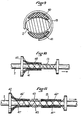
- the device represented in FIG. 5 is identical to FIG. 4 (the jacks and the hydraulic circuit have not been shown) except that the cables 13 have been replaced by a retaining sock 21 produced in a manner known in the form a sheet of woven threads, folded back on itself and sewn using a seam 22.
- chassis 11 and 16 are preferably produced in the form of half discs assembled by any suitable means in order to facilitate the installation of the device on the element 2.
- the device of FIG. 5 works in the same way as that of FIG. 4.
- the device of Figures 6 and 7 is similar to that of Figures 1 to 3 but the cylinders 10 are, in this embodiment, replaced by compression springs 23 disposed on the tubes 7 between the movable frame 11 and the fixed frame 4 to cause the moving chassis to move away from the fixed chassis.
- a lock 24 capable of being controlled by a control rod 25 makes it possible to lock the mobile chassis 11 in its position close to the fixed chassis 4, in which the cables 13 do not exert locking forces on the element 2.
- Cylinders 26 are mounted on the fitting 3 and have at the end of their rod 27, a pusher 28 capable of cooperating with a finger 29 mounted on the sleeve 8, to push the movable frame 11 in the direction opposite to the direction of scrolling FI, so as to bring the movable frame 11 into the position where it is locked using the latch 24.
- the rods 27 are retracted in the jacks 26 and the element 2 can move freely. If necessary, a control action is exerted on the rod 25, which has the effect of unlocking the latch 24, so that the springs 23 propel the frame 11 in the direction of travel FI, at a speed of the same order of magnitude as the running speed, which causes a tightening of cables 13 around the element 2 and blocks the latter.
- the spring therefore plays the role of motor and at the same time that of energy accumulator, the jacks 26 playing a role equivalent to that of the pump 51 in the embodiment of FIG. 1.
- the element 2 is unwound for example from a ship and passes over a drum 30.
- a retaining sock 31 is mounted at its upstream end on a chassis 32 and at its downstream end on a chassis 33.
- the upstream chassis is provided with rollers 34 similar to those described with reference to FIG. 4, and connected to the ship by means of a cable 35 connected to a support structure 36.
- the retaining sock 31 is compacted on itself in the longitudinal direction (or folded in zigzags as shown in FIG. 8), and maintained in this configuration by the fact that cables 37 forming loops capable of being very quickly detached , for example using explosive bolts 38, hold the upstream and downstream chassis connected.
- the retaining sock thus folded is engaged around a rigid sleeve 39 secured to the chassis 33 and arranged so that it prevents the retaining sock from coming into contact with the element 2 in normal operation.
- chassis 33 and the sleeve 39 play both the role of motor and of energy accumulator, here potential energy of gravitation.
- the retaining sock 31 can be replaced by two plies of cables wound in opposite directions.
- each ply can be placed on a sleeve, the sleeves being arranged concentrically.
- the element 2 here has an elliptical section and the pads 40 and 41 have a shape such that the assembly formed by the element 2 and the pads has a substantially circular section. This avoids, when tightening the cable 13, crushing or buckling of the element 2 in the direction of its major axis.
- the pads 40 and 41 are shown fixed to the upstream chassis 42, but of length less than the cables 13 in its deployed position shown in the figure.
- the downstream part of the cables 13 is therefore in contact with the element 2 and can thus ensure the tension of these cables.
- most of the effort blocking, which occurs in the upstream part of the cables 13, is taken up by the pads 40 and 41 which transmit it to the chassis 42, thus reducing the stresses exerted on the cables 13.
- pads 40 ', 40: “and 41', 41” having substantially the same length as the cables 13 once deployed, but then these pads are made in two parts connected in the longitudinal direction by elastic means 43. Under these conditions, the pads 40 "and 41” ensure the tensioning of the device while the pads 40 'and 41' ensure the transmission of the locking force to the upstream chassis 42.
Landscapes
- Engineering & Computer Science (AREA)
- General Engineering & Computer Science (AREA)
- Mechanical Engineering (AREA)
- Braking Arrangements (AREA)
- Tension Adjustment In Filamentary Materials (AREA)
- Supports For Pipes And Cables (AREA)
- Storing, Repeated Paying-Out, And Re-Storing Of Elongated Articles (AREA)
- Laying Of Electric Cables Or Lines Outside (AREA)
Applications Claiming Priority (2)
| Application Number | Priority Date | Filing Date | Title |
|---|---|---|---|
| FR8503951 | 1985-03-18 | ||
| FR8503951A FR2578930B1 (fr) | 1985-03-18 | 1985-03-18 | Dispositif a translation pour freiner le defilement d'un element allonge tel qu'un tuyau ou un cable |
Publications (2)
| Publication Number | Publication Date |
|---|---|
| EP0196962A1 true EP0196962A1 (de) | 1986-10-08 |
| EP0196962B1 EP0196962B1 (de) | 1989-01-18 |
Family
ID=9317290
Family Applications (1)
| Application Number | Title | Priority Date | Filing Date |
|---|---|---|---|
| EP86400572A Expired EP0196962B1 (de) | 1985-03-18 | 1986-03-18 | Vorrichtung um das Ablaufen eines länglichen Elements, wie ein Rohr, festzuhalten |
Country Status (9)
| Country | Link |
|---|---|
| US (1) | US5099959A (de) |
| EP (1) | EP0196962B1 (de) |
| JP (1) | JPH0774067B2 (de) |
| BR (1) | BR8606548A (de) |
| CA (1) | CA1257974A (de) |
| DE (2) | DE196962T1 (de) |
| ES (1) | ES8702603A1 (de) |
| FR (1) | FR2578930B1 (de) |
| WO (1) | WO1986005566A1 (de) |
Families Citing this family (6)
| Publication number | Priority date | Publication date | Assignee | Title |
|---|---|---|---|---|
| WO1993007404A1 (en) * | 1991-09-30 | 1993-04-15 | John Russell Place | Linear braking means |
| AU659684B2 (en) * | 1991-09-30 | 1995-05-25 | John Russell Place | Linear braking means |
| NL1006380C2 (nl) | 1997-06-24 | 1998-12-28 | Petrus Antonius Besselink | Geleider voor geleiding van bewegingen in twee tegenovergestelde richtingen en diverse inrichtingen voorzien van een dergelijke geleider. |
| NO320592B1 (no) * | 2004-03-01 | 2005-12-27 | Odim Seismic As | Anordning for lasing av langstrakte legemer |
| DE102006034848A1 (de) * | 2006-07-27 | 2008-01-31 | Siemens Ag | Schnurbremse |
| KR20170063514A (ko) | 2014-07-25 | 2017-06-08 | 에프. 호프만-라 로슈 아게 | 1밀리미터 미만의 체적을 가진 유체를 투여 |
Citations (3)
| Publication number | Priority date | Publication date | Assignee | Title |
|---|---|---|---|---|
| FR1593306A (de) * | 1968-11-21 | 1970-05-25 | ||
| FR2024176A1 (de) * | 1968-11-25 | 1970-08-28 | Shell Int Research | |
| US3975919A (en) * | 1974-10-15 | 1976-08-24 | Harrison Harry W | Pipeline positioning system |
Family Cites Families (4)
| Publication number | Priority date | Publication date | Assignee | Title |
|---|---|---|---|---|
| US2426631A (en) * | 1942-01-08 | 1947-09-02 | Specialties Dev Corp | Wire tensioning device |
| US3164335A (en) * | 1963-04-18 | 1965-01-05 | Possis Machine Corp | Wire tensioning apparatus |
| US3668878A (en) * | 1969-04-09 | 1972-06-13 | Brown & Root | Method and apparatus for laying pipelines |
| DE2748745A1 (de) * | 1977-10-29 | 1979-05-03 | Seipp Kg | Drahtbrems- und spannvorrichtungen insbesondere fuer drahtablaeufe |
-
1985
- 1985-03-18 FR FR8503951A patent/FR2578930B1/fr not_active Expired
-
1986
- 1986-03-17 CA CA000504245A patent/CA1257974A/fr not_active Expired
- 1986-03-18 JP JP61501693A patent/JPH0774067B2/ja not_active Expired - Lifetime
- 1986-03-18 BR BR8606548A patent/BR8606548A/pt not_active IP Right Cessation
- 1986-03-18 ES ES553422A patent/ES8702603A1/es not_active Expired
- 1986-03-18 DE DE198686400572T patent/DE196962T1/de active Pending
- 1986-03-18 DE DE8686400572T patent/DE3661862D1/de not_active Expired
- 1986-03-18 EP EP86400572A patent/EP0196962B1/de not_active Expired
- 1986-03-18 WO PCT/FR1986/000092 patent/WO1986005566A1/fr not_active Ceased
-
1988
- 1988-10-17 US US07/259,409 patent/US5099959A/en not_active Expired - Fee Related
Patent Citations (3)
| Publication number | Priority date | Publication date | Assignee | Title |
|---|---|---|---|---|
| FR1593306A (de) * | 1968-11-21 | 1970-05-25 | ||
| FR2024176A1 (de) * | 1968-11-25 | 1970-08-28 | Shell Int Research | |
| US3975919A (en) * | 1974-10-15 | 1976-08-24 | Harrison Harry W | Pipeline positioning system |
Also Published As
| Publication number | Publication date |
|---|---|
| FR2578930B1 (fr) | 1988-09-02 |
| EP0196962B1 (de) | 1989-01-18 |
| BR8606548A (pt) | 1987-08-04 |
| ES553422A0 (es) | 1987-01-16 |
| US5099959A (en) | 1992-03-31 |
| ES8702603A1 (es) | 1987-01-16 |
| JPS62502190A (ja) | 1987-08-27 |
| CA1257974A (fr) | 1989-08-01 |
| DE196962T1 (de) | 1987-04-30 |
| DE3661862D1 (en) | 1989-02-23 |
| JPH0774067B2 (ja) | 1995-08-09 |
| FR2578930A1 (fr) | 1986-09-19 |
| WO1986005566A1 (fr) | 1986-09-25 |
Similar Documents
| Publication | Publication Date | Title |
|---|---|---|
| EP0565445B1 (de) | Vorrichtung zum Verlegen eines mit einem Krümmungsbegrenzer versehenen flexiblen Rohrstrangs | |
| WO1991015699A1 (fr) | Dispositif et procede pour deroulement sensiblement vertical des conduites tubulaires flexibles | |
| EP2576414B1 (de) | Vorrichtung zum ergreifen und einstellen der spannung eines länglichen elements wie eines kabels, seils oder dergleichen | |
| FR2721635A1 (fr) | Dispositif de pose de conduites flexibles à partir d'un support flottant. | |
| EP4093666B1 (de) | Wölbvorrichtung für profilsegel | |
| EP0196962B1 (de) | Vorrichtung um das Ablaufen eines länglichen Elements, wie ein Rohr, festzuhalten | |
| FR2718665A1 (fr) | Outil de découpe de tuyauterie immergée par jet abrasif. | |
| BE1009966A3 (fr) | Carottier. | |
| FR2604697A1 (fr) | Appareil de manutention de cable | |
| EP0544573A1 (de) | Vorrichtung zur Verhinderung des Lockerns von Vorspannkabeln | |
| FR2777555A1 (fr) | Unite de detente de contraintes | |
| EP1110857A2 (de) | Vorrichtung zur Stabilisierung eines Schiffes, insbesondere beim Rollen | |
| FR2553396A1 (fr) | Fleche telescopique pour grue, nacelle ou plate-forme | |
| EP1303896B1 (de) | Vorrichtung zum verlegen eines mit einem pfropfen versehenen drahtes in ein rohr mittels druckluft sowie entsprechendes verfahren | |
| EP2643621A1 (de) | Vorrichtung zum spannen und befestigen eines länglichen, rohrförmigen elements | |
| EP0677437A1 (de) | Verfahren und Vorrichtung gegen die Längsbewegung von Wasserfahrzeugen | |
| FR2726533A1 (fr) | Dispositif de lancement d'un aeronef | |
| FR2964441A1 (fr) | Dispositif de mise sous tension de conduites tubulaires | |
| WO2018115787A1 (fr) | Methode et installation de reglage du pas des spires d'une carcasse metallique | |
| CA2533865C (fr) | Extracteur d'antenne lineaire remorquee ou d'objet similaire | |
| WO2015118085A1 (fr) | Actionneur lineaire a structure souple et bras articule comportant un tel actionneur | |
| FR2993293A1 (fr) | Dispositif de securite pour appareil leve plaque pour la pose de plaque dans le domaine du batiment | |
| FR2522081A1 (fr) | Verin moufle a double effet utilisable notamment pour commander les mouvements de fermeture et d'ouverture d'une porte coulissante ou basculante | |
| FR3137056A1 (fr) | Système de blocage et de déblocage d’élément longiligne avec enveloppe et deux éléments de fixation, un à chaque extrémité de l’enveloppe | |
| FR3070617A1 (fr) | Actionneur lineaire souple leger et systeme d’actionneur lineaire souple correspondant |
Legal Events
| Date | Code | Title | Description |
|---|---|---|---|
| PUAI | Public reference made under article 153(3) epc to a published international application that has entered the european phase |
Free format text: ORIGINAL CODE: 0009012 |
|
| AK | Designated contracting states |
Kind code of ref document: A1 Designated state(s): DE FR GB IT NL |
|
| ITCL | It: translation for ep claims filed |
Representative=s name: MODIANO & ASSOCIATI S.R.L. |
|
| 17P | Request for examination filed |
Effective date: 19861117 |
|
| TCNL | Nl: translation of patent claims filed | ||
| DET | De: translation of patent claims | ||
| 17Q | First examination report despatched |
Effective date: 19870902 |
|
| GRAA | (expected) grant |
Free format text: ORIGINAL CODE: 0009210 |
|
| AK | Designated contracting states |
Kind code of ref document: B1 Designated state(s): DE FR GB IT NL |
|
| REF | Corresponds to: |
Ref document number: 3661862 Country of ref document: DE Date of ref document: 19890223 |
|
| GBT | Gb: translation of ep patent filed (gb section 77(6)(a)/1977) | ||
| ITF | It: translation for a ep patent filed | ||
| PLBE | No opposition filed within time limit |
Free format text: ORIGINAL CODE: 0009261 |
|
| STAA | Information on the status of an ep patent application or granted ep patent |
Free format text: STATUS: NO OPPOSITION FILED WITHIN TIME LIMIT |
|
| 26N | No opposition filed | ||
| ITTA | It: last paid annual fee | ||
| PGFP | Annual fee paid to national office [announced via postgrant information from national office to epo] |
Ref country code: NL Payment date: 19940331 Year of fee payment: 9 |
|
| PGFP | Annual fee paid to national office [announced via postgrant information from national office to epo] |
Ref country code: DE Payment date: 19940526 Year of fee payment: 9 |
|
| PGFP | Annual fee paid to national office [announced via postgrant information from national office to epo] |
Ref country code: FR Payment date: 19950316 Year of fee payment: 10 |
|
| PG25 | Lapsed in a contracting state [announced via postgrant information from national office to epo] |
Ref country code: NL Effective date: 19951001 |
|
| NLV4 | Nl: lapsed or anulled due to non-payment of the annual fee |
Effective date: 19951001 |
|
| PG25 | Lapsed in a contracting state [announced via postgrant information from national office to epo] |
Ref country code: DE Effective date: 19951201 |
|
| PG25 | Lapsed in a contracting state [announced via postgrant information from national office to epo] |
Ref country code: FR Effective date: 19961129 |
|
| REG | Reference to a national code |
Ref country code: FR Ref legal event code: ST |
|
| PGFP | Annual fee paid to national office [announced via postgrant information from national office to epo] |
Ref country code: GB Payment date: 19980312 Year of fee payment: 13 |
|
| PG25 | Lapsed in a contracting state [announced via postgrant information from national office to epo] |
Ref country code: GB Free format text: LAPSE BECAUSE OF NON-PAYMENT OF DUE FEES Effective date: 19990318 |
|
| GBPC | Gb: european patent ceased through non-payment of renewal fee |
Effective date: 19990318 |
|
| PG25 | Lapsed in a contracting state [announced via postgrant information from national office to epo] |
Ref country code: IT Free format text: LAPSE BECAUSE OF NON-PAYMENT OF DUE FEES;WARNING: LAPSES OF ITALIAN PATENTS WITH EFFECTIVE DATE BEFORE 2007 MAY HAVE OCCURRED AT ANY TIME BEFORE 2007. THE CORRECT EFFECTIVE DATE MAY BE DIFFERENT FROM THE ONE RECORDED. Effective date: 20050318 |