EP0198197B1 - Capteur de pression différentielle de débit - Google Patents
Capteur de pression différentielle de débit Download PDFInfo
- Publication number
- EP0198197B1 EP0198197B1 EP86102924A EP86102924A EP0198197B1 EP 0198197 B1 EP0198197 B1 EP 0198197B1 EP 86102924 A EP86102924 A EP 86102924A EP 86102924 A EP86102924 A EP 86102924A EP 0198197 B1 EP0198197 B1 EP 0198197B1
- Authority
- EP
- European Patent Office
- Prior art keywords
- differential pressure
- fluid flow
- concavities
- flow sensor
- edges
- Prior art date
- Legal status (The legal status is an assumption and is not a legal conclusion. Google has not performed a legal analysis and makes no representation as to the accuracy of the status listed.)
- Expired - Lifetime
Links
- 239000012530 fluid Substances 0.000 title claims abstract description 39
- 230000003068 static effect Effects 0.000 claims abstract description 9
- 239000000523 sample Substances 0.000 description 49
- 238000007373 indentation Methods 0.000 description 27
- 238000013461 design Methods 0.000 description 6
- 230000002349 favourable effect Effects 0.000 description 4
- 238000004519 manufacturing process Methods 0.000 description 4
- 239000000463 material Substances 0.000 description 4
- 238000003754 machining Methods 0.000 description 3
- 238000000034 method Methods 0.000 description 3
- 230000002028 premature Effects 0.000 description 3
- 238000012937 correction Methods 0.000 description 2
- 238000001514 detection method Methods 0.000 description 2
- 238000009826 distribution Methods 0.000 description 2
- 238000005259 measurement Methods 0.000 description 2
- 238000007789 sealing Methods 0.000 description 2
- 230000015572 biosynthetic process Effects 0.000 description 1
- 238000002474 experimental method Methods 0.000 description 1
- 238000012805 post-processing Methods 0.000 description 1
- 238000007493 shaping process Methods 0.000 description 1
- 238000003860 storage Methods 0.000 description 1
- 238000012549 training Methods 0.000 description 1
- 238000011144 upstream manufacturing Methods 0.000 description 1
Images


Classifications
-
- G—PHYSICS
- G01—MEASURING; TESTING
- G01F—MEASURING VOLUME, VOLUME FLOW, MASS FLOW OR LIQUID LEVEL; METERING BY VOLUME
- G01F1/00—Measuring the volume flow or mass flow of fluid or fluent solid material wherein the fluid passes through a meter in a continuous flow
- G01F1/05—Measuring the volume flow or mass flow of fluid or fluent solid material wherein the fluid passes through a meter in a continuous flow by using mechanical effects
- G01F1/34—Measuring the volume flow or mass flow of fluid or fluent solid material wherein the fluid passes through a meter in a continuous flow by using mechanical effects by measuring pressure or differential pressure
- G01F1/36—Measuring the volume flow or mass flow of fluid or fluent solid material wherein the fluid passes through a meter in a continuous flow by using mechanical effects by measuring pressure or differential pressure the pressure or differential pressure being created by the use of flow constriction
- G01F1/40—Details of construction of the flow constriction devices
- G01F1/46—Pitot tubes
Definitions
- the invention relates to a differential pressure flow probe according to the features of the preambles of claims 1 and 2.
- a differential pressure flow probe which has a pitot tube with symmetrically distributed front baffle openings over its length for detecting the total pressure resulting from the addition of static and dynamic pressure in the fluid flow.
- a downstream probe opening for the detection of the static pressure.
- the pitot tube and the probe opening are connected via pipes to a measuring device, which causes a difference between the two tapped pressure values and thus determines the dynamic pressure in the fluid flow. As is known, this is proportional to the square of the speed of the fluid flow and thus the flow rate in the pipeline.
- the arrangement of the probe opening for the detection of the static pressure in the downstream area of the pitot tube has the advantage that the probe opening is in the suction of the pitot tube and thus in an area in which there is a considerably lower static pressure than the pressure in the free flow.
- the displayed differential pressure is then larger, which is desirable for a more precise display.
- the differential pressure flow probe described above has a round cross section.
- the disadvantages of such a training are described in detail in DE-A-28 42 676. They consist essentially in the fact that the flow stall on the jacket of the pitot tube with a round cross-section takes place at different points depending on the flow speed.
- DE-A-28 42 676 proposes various proposals for the design of the congestion probe or a body containing the probe opening. All embodiments have in common that the outer boundaries of the front surfaces of the pitot tube (FIGS. 1 to 6) or of the additional body (FIGS. 7 to 9) each end in an edge which is so sharp-edged that the one striking the front surfaces and tears off the flow boundary layer attached to it.
- the side and rear surfaces are designed so that the flow does not come back to the system after tearing off, so that - at least theoretically - the flow stall always takes place at the same point regardless of the flow speed.
- the profile according to the figures (1) and (4) in DE-A-28 42 676 has proven to be particularly favorable for the production.
- This profile for the pitot tube differs from a strictly square one in that the longitudinal edges are chamfered to such an extent that two parallel side faces and parallel front and rear faces are formed, which are derived from the original square profile, as shown in FIGS (6) DE-A-28 42 676 is shown to make an octagon.
- Such a cross section can be easily pulled or pushed. Machining is then only necessary for the holes in the dam and probe openings.
- the invention has for its object to develop a differential pressure flow probe of the type mentioned so that it delivers very good measured values despite relatively simple and inexpensive manufacture.
- This design is based on the knowledge already belonging to the invention that wedge-shaped front surfaces are favorable for the clean distribution of the fluid flow and for low resistance values, but not for the formation of the tear-off edges at their outer boundaries, especially if the pitot tube is produced inexpensively in a drawing process .
- the fluid flow hitting the front surfaces is now deflected more outwards than the wedge angle of the front surfaces, which results in a clean flow stall at the rear boundary edges of the indentations.
- the constant change of direction within the indentations prevents premature detachment and apparently gives the flow such a strong swirl to the outside that it has proven to be harmless if the front surfaces continue a little after the tear-off edges of the indentations. The flow does not reinstate.
- a particular advantage of this measure has been the fact that this design of the front sides can be produced without problems in a drawing process, without the need for post-processing.
- the limited edge sharpness that can be achieved with this is apparently compensated by the swirl imprinted by the arch shape of the indentations to such an extent that the tearing always takes place at the same point, which is expressed in a correction value that is constant over a very large speed range.
- the accuracy of the measured values is thus improved by the invention.
- the behavior of the differential pressure flow probe according to the invention is particularly unexpected and therefore surprising in two further aspects. It is known that very low-frequency fluctuations in measured values around the actual differential pressure value are characteristic of such probes. This makes reading the correct differential pressure value considerably more difficult. Measurements with the differential pressure flow probe designed according to the invention showed a strong reduction in such fluctuations in measured values with a correspondingly improved reading accuracy. Also surprising was the fact that the differential pressure is increased considerably, especially in the case of small pipe diameters, which likewise improves the reading accuracy. The deflection by the indentations is evidently increased in such a way that the afterflow area has a particularly low, static pressure in comparison to the free flow.
- the indentations on the front boundary edges are flowed as favorably as possible and that they run out on the rear boundary edges in such a way that the flow has a swirl which is directed outwards relative to the front surfaces receives and can therefore no longer abide by them.
- the following favorable values for this were determined in experiments.
- the front surfaces should enclose an angle of approximately 90 ° in a manner known per se. On the one hand, this provides favorable material cross sections for the indentation of the indentations and, on the other hand, allows a pronounced design of the tear-off edges.
- the tangents to the front boundary edges of the indentations should enclose an angle of 0 ° to 60 ° .
- Angular values between at least 20 ° and at most 40 ° have proven to be particularly advantageous.
- tangents to the rear boundary edges of the indentations are concerned, a range from 100 ° to 180 ° is preferred as the included angle. Angles between at least 130 ° and at most 160 ° have proven to be particularly suitable. The angle between the tangents to the rear boundary edges of the indentations and the subsequent front surface areas should be at least 20 °. This angle should be greater, the more the front surface continues in connection with the rear boundary edges of the indentations.
- the indentations each extend over at least 60 ° of the wedge-shaped sections of the front surfaces.
- the invention provides that the body having the probe opening (s) consists of a pushed or drawn section.
- the differential pressure flow probe (1) shown in FIGS. (1) and (2) has a pitot tube (2) which has four damming openings (3, 4, 5, 6) on one side. If the differential pressure flow probe (1) - as shown in Figure (2) - is installed in a pipe section (7), the damming openings (3, 4, 5, 6) are symmetrical to the pipe center axis and against the fluid flow, indicated by the arrow A. , directed.
- the lower end of the pitot tube (2) in this view is closed by a cap (8).
- This cap (8) lies against the inner wall of the pipe section (7) with a tip.
- a connecting tube (9) is coaxially welded to the upper open end of the pitot tube (2). It is closed at the top by a head piece (10) through which two connecting bores (11, 12) pass, each of which opens into a screw connection (13, 14) that goes away to the side.
- a measuring device for measuring the differential pressure can be connected to these screw connections (13, 14).
- connection hole (11) is connected via a through the connecting pipe (9) and to the center of the pitot tube (2) tube (15) with a probe opening (16) on the back of the pitot tube (2), namely so that the probe opening (16) has no connection to the interior of the pitot tube (2).
- the static pressure of the fluid flow is thus detected via this probe opening (16), while the dynamic pressure of the fluid flow prevails in the interior of the pitot tube (2) and the pipe section (7).
- the difference between the two pressure values is then proportional to the square of the flow rate.
- the differential pressure flow probe (1) is inserted within a pipe socket (17) which is welded to the pipe section (7).
- a union nut (18) is screwed onto the pipe socket (17) and clamps a sealing ring (19) in such a way that the differential pressure flow probe (1) is thereby fixed at the same time.
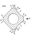
- the special feature of the differential pressure flow probe (1) according to the invention results in particular from Figure (3).
- the pitot tube (2) shown there in cross section is made from an octagonal tube section in its basic shape, so that eight longitudinal edges (20, 21, 22, 23, 24, 25, 26, 27) are formed accordingly. Since this pipe section was produced in one drawing process, these longitudinal edges (20 to 27) are not sharp, but rounded. As a result, a clean stall in the area of the outer longitudinal edges (22, 23) of the front surfaces (28, 29) could not be achieved.
- arcuate indentations (30, 31) are formed in the front surfaces (28, 29) in such a way that the outer boundaries of the indentations (30, 31) as tear-off edges (32, 33) are trained.
- the indentations (30, 31) which act like blades, deflect the fluid stream impinging on the pitot tube (2), indicated by the arrow B, markedly and without the possibility of premature detachment, so that the fluid flow at the tear-off edges (32, 33 ) flows out in the direction of arrows C and D and thereby tears off cleanly.
- the deflection is so pronounced that it is without influence that the front surfaces (28, 29) continue to widen following the tear-off edges (32, 33) until they turn into parallel side surfaces (34 , 35) pass over.
- the cross section of the pitot tube (2) tapers down to a rear surface (36), in which - not visible here - the probe opening (16) is formed.
- the storage openings (3, 4, 5, 6) - likewise not visible here - are located on the opposite side of the pitot tube (2), opposite the arrow B.
- the differential pressure flow probe (40) shown in FIGS. (4) and (5) has a continuous pitot tube (41), the lower end of which bears against the inner wall of a tube section (42) and the upper end of which opens into a head piece (43).
- the pitot tube (41) also has a total of four damming openings (44, 45, 46, 47), which are symmetrical in pairs to the longitudinal axis of the tube section (42) when the differential pressure flow probe (40), as shown in Figure (5), in the Pipe section (42) is installed.
- a probe tube (48) extends from the head piece (43), which opens on the underside into a probe body (49) and has a connection there to a downstream probe opening (50).
- the front of the probe body (49) is welded to the back of the pitot tube (41).
- Two connecting bores (51, 52) pass through the head piece (43), each of which opens into a screw connection (53, 54) going away to the side.
- a measuring device for detecting the differential pressure can be connected to these screw connections (53, 54).
- Pitot tube (41) and probe tube (48) are surrounded by a jacket tube (55) below the head piece (43) to somewhat above the tube section (42), the lower end of the jacket tube (55) being closed off with a welded-on plate (56) .
- the differential pressure flow probe (40) is inserted with the jacket tube (55) within a tube socket (57) welded to the tube section (42).
- a union nut (58) is screwed onto the pipe socket (57) and clamps one Sealing ring (59) in such a way that this simultaneously fixes the differential pressure flow probe (40).
- the special feature of the differential pressure flow probe (40) according to the invention results in particular from FIG. (6). It is a cross section through the pitot tube (41) and the probe body (49) between the lower end of the probe tube (48) and the probe opening (50).
- the probe body (49) has an arcuate indentation (60, 61) on the front, in such a way that the outer boundaries of the indentations (60, 61) form tear-off edges (62, 63).
- the indentations (60, 61) which act like blades, deflect the fluid stream impinging on the probe body (49) to the outside without the possibility of premature detachment, so that the fluid stream flows off at the tear-off edges (62, 63) and thereby tears off cleanly.
- Arrows E and F each indicate the direction of flow of the fluid flow.
- the probe body (49) can be cut from a drawn piece of material, but can also be produced by machining.
Landscapes
- Physics & Mathematics (AREA)
- Fluid Mechanics (AREA)
- General Physics & Mathematics (AREA)
- Measuring Volume Flow (AREA)
- Measuring Fluid Pressure (AREA)
- Measuring Pulse, Heart Rate, Blood Pressure Or Blood Flow (AREA)
Claims (12)
Priority Applications (1)
| Application Number | Priority Date | Filing Date | Title |
|---|---|---|---|
| AT86102924T ATE55010T1 (de) | 1985-04-11 | 1986-03-05 | Differentialdruckstroemungssonde. |
Applications Claiming Priority (2)
| Application Number | Priority Date | Filing Date | Title |
|---|---|---|---|
| DE3512960 | 1985-04-11 | ||
| DE3512960A DE3512960C2 (de) | 1985-04-11 | 1985-04-11 | Differenzdruckströmungssonde |
Publications (3)
| Publication Number | Publication Date |
|---|---|
| EP0198197A2 EP0198197A2 (fr) | 1986-10-22 |
| EP0198197A3 EP0198197A3 (en) | 1987-12-23 |
| EP0198197B1 true EP0198197B1 (fr) | 1990-07-25 |
Family
ID=6267715
Family Applications (1)
| Application Number | Title | Priority Date | Filing Date |
|---|---|---|---|
| EP86102924A Expired - Lifetime EP0198197B1 (fr) | 1985-04-11 | 1986-03-05 | Capteur de pression différentielle de débit |
Country Status (6)
| Country | Link |
|---|---|
| US (1) | US4703661A (fr) |
| EP (1) | EP0198197B1 (fr) |
| AT (1) | ATE55010T1 (fr) |
| AU (1) | AU586476B2 (fr) |
| DE (2) | DE3512960C2 (fr) |
| ZA (1) | ZA862067B (fr) |
Families Citing this family (30)
| Publication number | Priority date | Publication date | Assignee | Title |
|---|---|---|---|---|
| US4717159A (en) * | 1986-06-06 | 1988-01-05 | Dieterich Standard Corp. | Method and apparatus for seating and sealing a pitot tube type flow meter in a pipe |
| US5269353A (en) * | 1992-10-29 | 1993-12-14 | Gilbarco, Inc. | Vapor pump control |
| DE4417913C1 (de) * | 1994-05-21 | 1995-09-21 | Bundesrep Deutschland | Gasströmungssonde |
| DE19509208A1 (de) * | 1995-03-17 | 1995-12-07 | Systec Controls Mes Und Regelt | Staudrucksonde |
| DE19535486C1 (de) * | 1995-09-23 | 1996-12-05 | Bayerische Motoren Werke Ag | Drall-Meßverfahren für einen simulierten Verbrennungsraum eines Kolbenmotors und Vorrichtung zur Durchführung eines Drall-Meßverfahrens |
| US6589433B2 (en) | 1996-06-26 | 2003-07-08 | Simon Fraser University | Accelerometer without proof mass |
| US6182509B1 (en) | 1996-06-26 | 2001-02-06 | Simon Fraser University | Accelerometer without proof mass |
| WO1997049998A1 (fr) | 1996-06-26 | 1997-12-31 | Simon Fraser University | Accelerometre sans masselottes |
| US5756892A (en) * | 1997-02-27 | 1998-05-26 | The United States Of America As Represented By The United States National Aeronautics And Space Administration | Apparatus for measuring ambient pressure within a gaseous flow field |
| RU2135971C1 (ru) | 1998-07-06 | 1999-08-27 | Центральный аэрогидродинамический институт им.проф.Н.Е.Жуковского | Приемник воздушного давления |
| US6164143A (en) * | 1998-08-08 | 2000-12-26 | Dieterich Standard, Inc. | Tip flow barrier for a pitot tube type of fluid flowmeter |
| US6470755B1 (en) * | 1999-08-05 | 2002-10-29 | Dieterich Standard, Inc. | Noise reducing differential pressure measurement probe |
| GB9921489D0 (en) * | 1999-09-10 | 1999-11-17 | Univ Cambridge Tech | Sensor probe |
| US6487918B1 (en) | 2000-12-22 | 2002-12-03 | Mestek, Inc. | Airflow sensor for averaging total pressure |
| US6883389B2 (en) | 2003-08-21 | 2005-04-26 | Eldridge Products, Inc. | Flow averaging tube and method of using same |
| GB0426007D0 (en) * | 2004-11-26 | 2004-12-29 | Univ Gent | Method and device for measuring pressure |
| US7735371B2 (en) | 2005-01-26 | 2010-06-15 | Systec Controls Mess-Und Regelungstechnik Gmbh | Dynamic pressure probe with adapters fitted on the probe head |
| US7654160B2 (en) * | 2006-12-20 | 2010-02-02 | Electric Power Research Institute, Inc. | Sampling probe enabling the measurement of gaseous species in particle-laden flue gas |
| GB2446827B (en) * | 2007-02-23 | 2011-06-29 | Associated Instr Repairs Ltd | Pitot-static device |
| CA2692535C (fr) * | 2009-04-23 | 2016-04-05 | Syncrude Canada Ltd. | Recipient d'echantillonnage pour solides fluidifies |
| US8413501B2 (en) * | 2010-03-26 | 2013-04-09 | The Boeing Company | Wake measurement probe |
| US8960018B2 (en) * | 2013-03-14 | 2015-02-24 | Dieterich Standard, Inc. | Pitot tube traverse assembly |
| CA2826516C (fr) * | 2013-08-30 | 2020-09-22 | Protecsom Amerique Du Nord Inc. | Appareil de mesure de debit et appareil d'inhalation comportant celui-ci |
| US9250108B2 (en) | 2013-09-27 | 2016-02-02 | Rosemount Inc. | Differential pressure based flow measurement device having improved pitot tube configuration |
| US9494451B1 (en) * | 2015-03-26 | 2016-11-15 | The United States Of America As Represented By The Secretary Of The Navy | Pitot tube support and alignment apparatus |
| US9996089B2 (en) * | 2015-09-21 | 2018-06-12 | Blue-White Industries, Ltd. | Flow sensor devices and systems |
| US11150118B2 (en) * | 2016-09-23 | 2021-10-19 | Blue-White Industries, Ltd. | Flow sensor devices and systems |
| CN108871470A (zh) * | 2018-06-14 | 2018-11-23 | 东莞理工学院 | 一种新型插入式差压流量计 |
| US11639863B2 (en) | 2019-06-07 | 2023-05-02 | Blue-White Industries, Ltd. | Flow sensor devices and systems |
| DE202020102087U1 (de) | 2020-04-15 | 2021-07-16 | Postberg + Co. GmbH | Messsonde |
Family Cites Families (5)
| Publication number | Priority date | Publication date | Assignee | Title |
|---|---|---|---|---|
| US1508017A (en) * | 1922-12-11 | 1924-09-09 | Frederick W Greve | Pitometer |
| US2197214A (en) * | 1938-04-26 | 1940-04-16 | Byron Jackson Co | Flow meter |
| US3581565A (en) * | 1968-07-15 | 1971-06-01 | Peter D Dieterich | Flow-measuring device |
| US4154100A (en) * | 1978-01-09 | 1979-05-15 | Dieterich Standard Corp. | Method and apparatus for stabilizing the flow coefficient for pitot-type flowmeters with a downstream-facing port |
| US4559836A (en) * | 1984-10-17 | 1985-12-24 | Dieterich Standard Corp. | Pitot type flow measuring device and method of mounting |
-
1985
- 1985-04-11 DE DE3512960A patent/DE3512960C2/de not_active Expired
-
1986
- 1986-03-05 AT AT86102924T patent/ATE55010T1/de not_active IP Right Cessation
- 1986-03-05 DE DE8686102924T patent/DE3672870D1/de not_active Expired - Fee Related
- 1986-03-05 EP EP86102924A patent/EP0198197B1/fr not_active Expired - Lifetime
- 1986-03-11 US US06/838,609 patent/US4703661A/en not_active Expired - Lifetime
- 1986-03-20 ZA ZA862067A patent/ZA862067B/xx unknown
- 1986-03-27 AU AU55348/86A patent/AU586476B2/en not_active Ceased
Also Published As
| Publication number | Publication date |
|---|---|
| ATE55010T1 (de) | 1990-08-15 |
| EP0198197A2 (fr) | 1986-10-22 |
| DE3512960C2 (de) | 1987-03-05 |
| EP0198197A3 (en) | 1987-12-23 |
| AU5534886A (en) | 1986-10-16 |
| ZA862067B (en) | 1986-11-26 |
| DE3512960A1 (de) | 1986-10-16 |
| DE3672870D1 (de) | 1990-08-30 |
| AU586476B2 (en) | 1989-07-13 |
| US4703661A (en) | 1987-11-03 |
Similar Documents
| Publication | Publication Date | Title |
|---|---|---|
| EP0198197B1 (fr) | Capteur de pression différentielle de débit | |
| DE2842676C2 (de) | Staurohr-Durchflußmeßgerät | |
| EP2172657B1 (fr) | Guide d'écoulement pour un appareil de mesure du débit, notamment un appareil de mesure à ultrasons | |
| DE2212746C3 (de) | Strömungsrichter | |
| DE69617438T2 (de) | Einzelstrahlflüssigkeitsströmungsmesser mit vergrössertem drehmoment | |
| DE2244178A1 (de) | Durchflussmesser fuer fluessigkeiten | |
| DE3113112C2 (fr) | ||
| DE2647297C3 (de) | Flügelradzahler | |
| DE2951186A1 (de) | Stroemungsmesser des stroemungstau- typs | |
| DE2612175C3 (de) | Düse zum tropfenweisen Aufbringen von Waschflüssigkeit auf eine Waschstelle | |
| DE3714344C2 (fr) | ||
| DE3437249A1 (de) | Stroemungsmesseinrichtung mit niedrigem energieverlust | |
| DE2248891C3 (de) | Schieberkolben für ein hydraulisches Mehrwegeventil | |
| DE3112959A1 (de) | Turbinenlaeufer eines durchflussmessers | |
| EP0007111A2 (fr) | Dispositif de mesure de l'écoulement suivant le pincipe des tourbillons de Kármán | |
| DE1798392A1 (de) | Fluegelraddurchflussmesser | |
| DE69316471T2 (de) | Wirbeldurchflussmesser | |
| EP0407948B2 (fr) | Compteur de liquide à turbine pour mesurer un débit | |
| DE2112088C2 (de) | Wirbelerzeugende Vorrichtung zum Einbau in ein Wirbelrohr eines Zentrifugalabscheiders | |
| EP0327103A2 (fr) | Débitmètre à fréquence de tourbillons | |
| EP0049756A1 (fr) | Dispositif pour la mesure de pression différentielle | |
| EP3575753B1 (fr) | Débitmètre à induction magnétique et tube de mesure | |
| DE2305710B2 (de) | Venturi-Wäscher | |
| DE977410C (de) | Stroemungsmesser | |
| EP0309820A2 (fr) | Raidisseur pour gaines d'aération |
Legal Events
| Date | Code | Title | Description |
|---|---|---|---|
| PUAI | Public reference made under article 153(3) epc to a published international application that has entered the european phase |
Free format text: ORIGINAL CODE: 0009012 |
|
| AK | Designated contracting states |
Kind code of ref document: A2 Designated state(s): AT BE CH DE FR GB IT LI LU NL SE |
|
| PUAL | Search report despatched |
Free format text: ORIGINAL CODE: 0009013 |
|
| AK | Designated contracting states |
Kind code of ref document: A3 Designated state(s): AT BE CH DE FR GB IT LI LU NL SE |
|
| 17P | Request for examination filed |
Effective date: 19871111 |
|
| 17Q | First examination report despatched |
Effective date: 19890918 |
|
| RAP3 | Party data changed (applicant data changed or rights of an application transferred) |
Owner name: INTRA AUTOMATION GMBH MESS- UND REGELINSTRUMENTE |
|
| GRAA | (expected) grant |
Free format text: ORIGINAL CODE: 0009210 |
|
| AK | Designated contracting states |
Kind code of ref document: B1 Designated state(s): AT BE CH DE FR GB IT LI LU NL SE |
|
| REF | Corresponds to: |
Ref document number: 55010 Country of ref document: AT Date of ref document: 19900815 Kind code of ref document: T |
|
| GBT | Gb: translation of ep patent filed (gb section 77(6)(a)/1977) | ||
| REF | Corresponds to: |
Ref document number: 3672870 Country of ref document: DE Date of ref document: 19900830 |
|
| ITF | It: translation for a ep patent filed | ||
| ET | Fr: translation filed | ||
| PG25 | Lapsed in a contracting state [announced via postgrant information from national office to epo] |
Ref country code: LU Free format text: LAPSE BECAUSE OF NON-PAYMENT OF DUE FEES Effective date: 19910331 |
|
| PLBI | Opposition filed |
Free format text: ORIGINAL CODE: 0009260 |
|
| 26 | Opposition filed |
Opponent name: DELAWARE CAPITAL FORMATION, INC. Effective date: 19910424 |
|
| NLR1 | Nl: opposition has been filed with the epo |
Opponent name: DELAWARE CAPITAL FORMATION, INC. |
|
| PGFP | Annual fee paid to national office [announced via postgrant information from national office to epo] |
Ref country code: AT Payment date: 19930330 Year of fee payment: 8 |
|
| PGFP | Annual fee paid to national office [announced via postgrant information from national office to epo] |
Ref country code: BE Payment date: 19930406 Year of fee payment: 8 |
|
| PGFP | Annual fee paid to national office [announced via postgrant information from national office to epo] |
Ref country code: CH Payment date: 19930419 Year of fee payment: 8 |
|
| PGFP | Annual fee paid to national office [announced via postgrant information from national office to epo] |
Ref country code: GB Payment date: 19940224 Year of fee payment: 9 |
|
| PG25 | Lapsed in a contracting state [announced via postgrant information from national office to epo] |
Ref country code: AT Effective date: 19940305 |
|
| PGFP | Annual fee paid to national office [announced via postgrant information from national office to epo] |
Ref country code: FR Payment date: 19940318 Year of fee payment: 9 |
|
| PGFP | Annual fee paid to national office [announced via postgrant information from national office to epo] |
Ref country code: SE Payment date: 19940329 Year of fee payment: 9 |
|
| PG25 | Lapsed in a contracting state [announced via postgrant information from national office to epo] |
Ref country code: LI Effective date: 19940331 Ref country code: CH Effective date: 19940331 Ref country code: BE Effective date: 19940331 |
|
| PGFP | Annual fee paid to national office [announced via postgrant information from national office to epo] |
Ref country code: NL Payment date: 19940331 Year of fee payment: 9 |
|
| BERE | Be: lapsed |
Owner name: INTRA AUTOMATION G.M.B.H. MESS- UND REGELINSTRUME Effective date: 19940331 |
|
| REG | Reference to a national code |
Ref country code: CH Ref legal event code: PL |
|
| EAL | Se: european patent in force in sweden |
Ref document number: 86102924.7 |
|
| PG25 | Lapsed in a contracting state [announced via postgrant information from national office to epo] |
Ref country code: GB Effective date: 19950305 |
|
| PG25 | Lapsed in a contracting state [announced via postgrant information from national office to epo] |
Ref country code: SE Effective date: 19950306 |
|
| PLBN | Opposition rejected |
Free format text: ORIGINAL CODE: 0009273 |
|
| STAA | Information on the status of an ep patent application or granted ep patent |
Free format text: STATUS: OPPOSITION REJECTED |
|
| 27O | Opposition rejected |
Effective date: 19950517 |
|
| PG25 | Lapsed in a contracting state [announced via postgrant information from national office to epo] |
Ref country code: NL Effective date: 19951001 |
|
| NLR2 | Nl: decision of opposition | ||
| GBPC | Gb: european patent ceased through non-payment of renewal fee |
Effective date: 19950305 |
|
| PG25 | Lapsed in a contracting state [announced via postgrant information from national office to epo] |
Ref country code: FR Free format text: LAPSE BECAUSE OF NON-PAYMENT OF DUE FEES Effective date: 19951130 |
|
| NLV4 | Nl: lapsed or anulled due to non-payment of the annual fee |
Effective date: 19951001 |
|
| EUG | Se: european patent has lapsed |
Ref document number: 86102924.7 |
|
| REG | Reference to a national code |
Ref country code: FR Ref legal event code: ST |
|
| PGFP | Annual fee paid to national office [announced via postgrant information from national office to epo] |
Ref country code: DE Payment date: 19970326 Year of fee payment: 12 |
|
| PG25 | Lapsed in a contracting state [announced via postgrant information from national office to epo] |
Ref country code: DE Free format text: LAPSE BECAUSE OF NON-PAYMENT OF DUE FEES Effective date: 19981201 |
|
| PG25 | Lapsed in a contracting state [announced via postgrant information from national office to epo] |
Ref country code: IT Free format text: LAPSE BECAUSE OF NON-PAYMENT OF DUE FEES Effective date: 20050305 |
|
| APAH | Appeal reference modified |
Free format text: ORIGINAL CODE: EPIDOSCREFNO |