EP0198992A1 - Two-stage baler - Google Patents
Two-stage baler Download PDFInfo
- Publication number
- EP0198992A1 EP0198992A1 EP19850830259 EP85830259A EP0198992A1 EP 0198992 A1 EP0198992 A1 EP 0198992A1 EP 19850830259 EP19850830259 EP 19850830259 EP 85830259 A EP85830259 A EP 85830259A EP 0198992 A1 EP0198992 A1 EP 0198992A1
- Authority
- EP
- European Patent Office
- Prior art keywords
- pressing
- group
- walls
- plant according
- final
- Prior art date
- Legal status (The legal status is an assumption and is not a legal conclusion. Google has not performed a legal analysis and makes no representation as to the accuracy of the status listed.)
- Granted
Links
- 239000000463 material Substances 0.000 claims abstract description 79
- 239000004753 textile Substances 0.000 claims abstract description 6
- 230000015572 biosynthetic process Effects 0.000 claims abstract description 5
- 210000001520 comb Anatomy 0.000 claims description 11
- 230000006835 compression Effects 0.000 claims description 3
- 238000007906 compression Methods 0.000 claims description 3
- 239000004033 plastic Substances 0.000 claims description 3
- 229920003023 plastic Polymers 0.000 claims description 3
- VYZAMTAEIAYCRO-UHFFFAOYSA-N Chromium Chemical compound [Cr] VYZAMTAEIAYCRO-UHFFFAOYSA-N 0.000 claims description 2
- 229910052804 chromium Inorganic materials 0.000 claims description 2
- 239000011651 chromium Substances 0.000 claims description 2
- 238000006073 displacement reaction Methods 0.000 description 5
- 238000010073 coating (rubber) Methods 0.000 description 1
- 238000010276 construction Methods 0.000 description 1
- 230000000694 effects Effects 0.000 description 1
- 238000009434 installation Methods 0.000 description 1
- 238000004806 packaging method and process Methods 0.000 description 1
- 239000002985 plastic film Substances 0.000 description 1
- 229920006255 plastic film Polymers 0.000 description 1
- 230000000750 progressive effect Effects 0.000 description 1
- 230000000284 resting effect Effects 0.000 description 1
- 239000007787 solid Substances 0.000 description 1
- 230000008961 swelling Effects 0.000 description 1
Images


Classifications
-
- B—PERFORMING OPERATIONS; TRANSPORTING
- B65—CONVEYING; PACKING; STORING; HANDLING THIN OR FILAMENTARY MATERIAL
- B65B—MACHINES, APPARATUS OR DEVICES FOR, OR METHODS OF, PACKAGING ARTICLES OR MATERIALS; UNPACKING
- B65B27/00—Bundling particular articles presenting special problems using string, wire, or narrow tape or band; Baling fibrous material, e.g. peat, not otherwise provided for
- B65B27/12—Baling or bundling compressible fibrous material, e.g. peat
- B65B27/125—Baling or bundling compressible fibrous material, e.g. peat and wrapping or bagging
-
- B—PERFORMING OPERATIONS; TRANSPORTING
- B30—PRESSES
- B30B—PRESSES IN GENERAL
- B30B9/00—Presses specially adapted for particular purposes
- B30B9/30—Presses specially adapted for particular purposes for baling; Compression boxes therefor
- B30B9/3078—Presses specially adapted for particular purposes for baling; Compression boxes therefor with precompression means
Definitions
- the invention relates to a pressing plant of the type to be utilized for example, but not exclusively, for the formation of bales of textile pressed materials for the textile industry.
- these plants are usually developed in height in order to operate both a pre-compression and the final pressing within a same room or space vertically developed and which is, therefore, at least partially underground; this brings about high costs and difficulty of installation.
- the plant according to the invention is realized to avoid excessive development in height of the plant and, hence, its placing underground.
- the pressing plant according to the invention - for the formation of bales of pressed textile materials comprises: a first pressing group, associated with means for the loading of the material; a second group of final pressing, associated with binding means, and, possibly, with film - or other -:wrapping means; and an apparatus for transferring the partially pressed material from the first group to the second group.
- the two groups are substantially on the same level.
- the transfer apparatus may comprise two opposite walls for retaining the partially pressed material; a transverse pusher associated with said first group, which defines a Wall to retain the loaded material; and a second retaining wall, opposite to the pusher and apt to be defiled, that is shifted, when the pusher has to transfer the material partially pressed between said two opposite walls.
- the opposite walls are advantageously grid-like developed, with bars parallel to the direction of movement of the transverse pusher to reduce the friction on the material.
- the opposite walls grid-like developed are part of a carriage structure which moves between two positions in front of either of the two groups which are located side-by-side; an additional pusher is provided to push the partially pressed material from the carriage structure into the second group of final pressing.
- This additional pusher may be in a fixed location or may be installed on the carriage structure.
- the two groups are placed opposite to one another in the direction according which said first pusher acts; the two groups are spaced apart and the two facing walls are disposed therebetween for the transfer of the partially pressed material.
- These opposite, grid--shaped walls may be articulated to the first pre-pressing group and form, by themselves, the second retaining wall when they are brought down towards said first group; said two grid-like walls may have the bars of one wall interposed between those of the other, when the two walls are brought down towards said first group to form the retaining wall.
- the additional pusher is provided with stems that - upon the transfer operation into the second group of final pressing - are able to slide, together with the mass or bulk of the material, against the pressing walls and against the films, whereas, upon the back run of the pusher, said stems slide easily as they slip from the material and the films.
- said carriage comprises side walls apt to define the filling and pressing space, one of which being mobile, upper horizontal mobile combs and a shifting lower diaphragm; means are also provided apt to handle said combs and said diaphragm in order to retain, during the preliminary pressing and during the transfer, the pressed material within the pressing group and to be excluded during the final pressing, and means for handling the mobile wall to open it after the final pressing and allow the carriage to move away.
- the lower diaphragm can slide in its own plane, while the upper blades are movable around the pivots in order to reach the opening and closing positions on the first pressing group; the lower diaphragm closes when the blades forming the upper diaphragm are opened for the loading operations, and both said diaphragms are defiled, that is shifted, after the transfer to the position on the second group of final pressing,to allow the final pressing.
- the horizontal lower diaphragm may be developed as a continuous lamina or as a grid or formed by rods parallel to the sliding direction and compatible with the possible slots provided in the compression walls of the second group of final pressing for the binding; the upper blades are shaped like curved combs,
- number 1 indicates the base of a first pressing group having a portal 3, which is associated with means for the loading of the material generally indicated by 5, of a per se traditional type for loading the material in a room or space where it is to be repeatedly compressed.
- the pre-pressing group presents a room, for receiving the material to be pressed, defined by a lower surface 7, two fixed opposite side walls 9 which define said room together with a pusher 10 operated by an actuator system 12 which acts in the horizontal direction according to f10; at the opposite side of the pusher 10 a second retaining wall 14 is provided which is intended to be moved to carry out the transfer; by way of example, this wall is moved in its own plane according to arrow f14, but it might be also removed in another suitable manner.
- Number 16 indicates the pressing system of said first pre-pressing group, able to operate with its own presser 16A in the well of the containing room of said first group.
- Number 18 indicates the base of a second group for final pressing, whose portal is indicated by 20, some components of which may be in common with those of portal 3.
- Number . 22 indicates the base or lower fixed plane of the final press, number 24 the mobile plane of the final press and number 26 indicates the power system for said final pressing group.
- a binding system and, possibly, also a wrapping system is associated, both per se known for these purposes in the traditional presses for textile materials; in particular, the bale-wrapping film may be developed into two sections which are laid against the opposite active surfaces of the stationary plane 22 and of the mobile plane 24, the films being possibly fed from corresponding coil-shaped tanks. The wrapping up of the pressed bale by said films is carried out just before the binding which, thereby, retains as well the protection envelope formed by said films. All these solutions are per se known and require some space around the pressing zone of the final pressing group.
- the pressing plant is completed by an apparatus for the transfer of partially pressed material from the first pressing group up to the second group of final pressing.
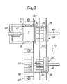
- the transfer is operated by a movement according to arrows f T shown in Figs.2 and 3, and to this purpose, rails 30 may be provided, roughly shown in Figs.1 and 3, and developing in front of the two groups.
- a carriage 32 which makes part of the transfer apparatus slides.
- the carriage has a pair of horizontal, spaced apart, facing walls 14, 36 which are typically made up - as can be seen in detail in Fig.2 - of sets of parallel and spaced apart bars developing in the direction f10 of the displacement of pusher 10, 12, that is, orthogonally to rails 20.
- the distance in the ver tical direction between the two bars-shaped walls 34, 36 is just slightly greater than the bulk dimensions of the material preliminarily pressed in the first pre-pressing group, and which is generically indicated by M; these two walls 34, 36 are also spaced little more than the size corresponding to the pusher 10.
- a pusher 38 develops, driven by an actuator 40 for a movement according to f38 and in opposite direction.
- the wall 14 also develops between the two facing bars-shaped walls 34, 36 to allow its displacement according to arrow f14.
- the material is put into the well delimited by the lower wall 7, the retaining wall 14, the wall of pusher 10 and the two fixed walls 9; by means of system 16, 16A, the material is then compacted in the inside of said well to carry out a preliminary pressing or pre-pressing.
- the wall 14 is made to slide according to f14 in order to defile it from the mass or bulk M, and the actuator 12 of the pusher 10 is operated to cause a translation, according to f10, of the partially pressed material M to insert it between the two bars-shaped walls 34, 36, the pusher 38 being drawn . back.
- the sliding operated by the pusher 10 is made easier in that the two opposite walls 34, 36 are bars--like developed and, hence, their friction on the material is greatly limited.
- the bulk of the preliminarily pressed material is thus between the two opposite walls 34, 36 and can be moved by the carriage 32 according to arrow f T to take it from the position in front of the first pre-pressing group up to the position in front of the second group of final pressing, that is, in alignment with the fixed bottom wall 22.
- the pusher 38 is moved by the actuator 40 according to arrow f38 until the bulk of the partially pressed material is introduced between the two walls 22 and 24 which are just a little more spaced apart than the bars--like opposite walls 34, 36 of carriage 32.
- the final pressing is operated by the system 26, without any retaining wall as the material is compacted enough for carrying out its final pressing without any trend to widening.
- the plastic film, if any, for the wrapping of the bale - which film is laid against the active surfaces of the pressing walls 22 and 24 - helps the sliding of the partially pressed material M, owing to the limited friction that these films present over the sliding of the material, whereas these films have not, practically, the tendency to slide respect to the surfaces of the pressing walls 22 and 24; to ensure these conditions, small rubber coatings located on the pressing plates may be provided to assure a sufficient friction between said plates and the films.
- the pusher 40 might also be in a fixed position in front of the final-pressing group.
- the corresponding members are indicated by the same references.
- the wall 14 is lacking, and in its place two grid-like walls 134 and 136 are provided which are also intended to replace the walls 34 and 36; these walls 134 and 136 are articulated at 138 and 140 to the structure of the first pressing group, for example, to the retaining walls 9 of said group.
- the two articulated walls 134 and 136 are developed in the form of mutually parallel and staggered bars and like tines having free mobile ends, in such a way that the two bar-shaped walls 134 and 136 can be shifted from a horizontal arrangement, as shown in Figs.4 and 5, to a vertical and coplanar arrangement as illustrated in Fig.6 in a front view.
- the bars-shaped wall 134 is lowered down until it rests on a fixed pawl 142 and the bars-shaped wall 136 is raised until it abuts against an upper fixed pawl 144.
- the two pawls 142 and 144 are carried by a portal structure 120 making part of the second group of final pressing, which is located - rather than side by side as in the previous instance - opposite that is facing in the direction of arrow f10 and spaced to a limited degree respect to the first group formed by the portal structure 1, 3.
- the distance between the group 1, 3 and the one indicated by 120 corresponds to the length of the bars of the opposite walls 134 and 136; this distance is sufficient to place the wrapping and binding systems in combination with the second group 120 for the final pressing.
- the retaining wall 14 may be replaced directly by the bars of the two angularly movable walls 134 and 136 which, once brought against the first group, are arranged with the bars interposed therebetween to make up the retaining wall.
- the bars-shaped walls 134 and 136 are shifted into their horizontal arrangement and a push system 110, 112 - equivalent to the one indicated by 10 but with a .
- a first pressing group is provided with a presser 116A (corresponding to the one indicated by 16A) having channels 116B relatively deep and oriented in the direction of the removal of the material block partially pressed therein.
- the lower contrast surface 107 of the pre-pressing group is realized with channels . 107B similar to those indicated by 116B.
- the lower contrast surface 107 of the pre-pressing group is made movable through a lower cylinder-piston system 108 which allows limited displacements.
- the pressing space of the pre-pressing group is defined, besides by the two surfaces 116A and 107, by a fixed wall 111 and two opposite walls 112 which are movable and, in particular, - according to the drawing - are articulated on top at 114 to be moved away, to some extent, the one from the other and from the lower surface 107.
- the front opposite to the wall 111 is closed - during the loading and the pre-pressing operations - by a mobile wall 120 of a pusher driven by a system 122 which has, in part, the function of system 38, 40 of the firstly described embodiment.
- the pusher 120, 122 is mounted on a carriage structure 124 which can be moved according to arrow f124 and in opposite direction towards and from the pre-pressing zone delimited by the walls 110 and 112, parallel to the movement direction of the pusher 120, 122. Therefore, said carriage slides on rails 126 which, in turn, are formed on a carriage 128 which is to be moved along rails 130 substantially corresponding to those indicated by 30 of the firstly illustrated example.
- the carriage 128 may be moved (likewise the one indicated by 32, previously described) between the position in front of the pre-pressing . system and the position in front of the final pressing system, which includes the mobile walls 22 and 24.
- the carriage 124 forms an upper fork 224 and a lower fork 324 which are able to fit into the channels 116B and respectively 107B, when the surfaces 116A and 107 are in the position of maximum approach for the final-pressing stage.
- the surface 107 is lifted from the system 108 to the position in which the channels 107B result lined up with the lower fork 324.
- the carriage 124 finds itself in a position with the forks 324 being outside and lined up with the channels 107B.
- the mobile wall 120 of the pusher 120, 122 of carriage 124 is shifted to the position indicated by 120X in which said wall 120 completes the loading tank or box further formed by the walls 112 brought close to one another, by the surface 107 and the wall 110 opposite to the wall 120. Under these conditions, the loading and the successive stages for the pre-pressing of the material by the systems 16 and 116A are carried out.
- the surface 116A finds itself lowered in such a way as to present its channels 1163 in alignment with the upper fork 224. Under these conditions, the carriage 124 is caused to advance according to arrow f124, while the wall 120 is kept stationary, this wall withdrawing
- the forks 224 and 324 fit into the channels 116B and 170B in the arrangement shown in 224X and 324X; after that, the wall 107 is lowered and the wall 116A is lifted so that the material which has been subjected to the pre-pressing operation will come in contrast with forks 224 and 324. At this point, the walls 112 are moved apart; the carriage 124 is moved in the direction opposite to the one indicated by arrow f124; the bulk of the preliminarily pressed material which is between the two forks 224, 324, as indicated by M in Fig.7, is moved away from the pre--pressing group.
- the carriage 128, bearing the guides 126 of the carriage 124 is moved from the position in front of the pre-pressing zone up to the position in front of the final press, that is, in alignment with walls 22 and 24, the latter being lifted to such an extent that the interspace between said walls 22 and 24 is slightly greater than the interspace between forks 224 and 324.
- a film of plastic material is placed and then, by means of the push system 120, 122, the bulk of material M, is pushed between the walls 22 and 24 thus causing it to slide along the bars of forks 224 and 324 up to the position where the final pressing, the wrapping and the binding of the bale will take place.
- the pressing space of the pre-pressing group is defined, besides by the two surfaces 1116A and 1107, by a fixed wall 1111 and two opposite walls 1112 which are movable and, in particular - according to the drawing - articulated on top at 1114 so that they can be moved, to a limited extent, away from one another and from the lower surface 1107.
- the front opposite to wall 1111 is closed - during the loading and the pre--pressing operations - by a wall 1118 which can be defiled that is shifted, by a sliding on its plane or otherwise removed.
- a mobile wall is indicated of a pusher operated by a system 1122.
- the pusher 1120, 1122 is mounted on a carriage structure 1124 which can be moved, according to arrow 1124 and in opposite direction, towards and from the pre-pressing zone delimited by the walls 1110 and 1112, parallel to the direction of displacement of pusher 1120, 1122.
- Said carriage slides on rails 1126 which are, in turn, formed on a carriage 1128 which is intended to be moved along the rails 1130.
- the carriage 1128 can be moved between the position in front of the pre-pressing system and the position in front of the final pressing system, which comprises the mobile walls 1022 and 1024 and the group 1026 on the frame 1020.
- the carriage 1124 forms an upper fork 1224 and a lower fork 1324 which are apt to fit into channels 1116B and respectively 1107B when the surfaces 1116A and 1107 are arranged as close as possible to each other for the final stage of pre-pressing.
- the mobile wall 1120 of the pusher 1120, 1122 is provided with a double set of stems 1420, 1430 which are interposed between the bars 1224 and between the ones indicated by .1324 at an intermediate level relative to them.
- Said stems have a very smooth surface, being for example chromium plated, and are of very limited dimensions being able to be, for example, rod-shaped; they are not required to be particularly resistant to stresses by the pressed material.
- the purpose of these stems 1420 and 1430 will be better described hereinafter.
- the surface 1107 is lifted from the system 1108 to a position in which the channels 1107B result lined up with the lower fork 1324.
- the carriage 1124 finds itself in a position with the forks 1324 outside of and lined up with the channels 1107B.
- the mobile wall 1120 of the pusher 1120, 1122 of the carriage 1124 is, in this case, kept in back position, and the said shifting wall 1118 is provided, in order to complete the loading tank being further formed by walls 1112, drawn close to one another, by the surface 1107 and the wall 1110. Under these conditions, the loading and the subsequent stages of pre-pressing of the material by systems 1016 and 1116 are carried out.
- the surface 1116A is lowered in such a way as to present its channels 1116B in alignment with the upper fork 1224.
- the wall 1118 is moved away and the carriage 1124 is caused to advance according to arrow 1124, together with wall 1120 with stems.1420 and 1430.
- the forks 1224 and 1324 fit into the channels 1116B and 1107 in the arrangement shown by 1224X and 1324X; after that, the wall 1107B is lowered and the wall 1116A is raised so that the material, which has been subjected to the pre-pressing operation, will come to contrast on forks 1224 and 1324.
- the walls 1112 are moved away from each other and the carriage 1124 is moved in the direction opposite to the one indicated by arrow f1124; the bulk of the preliminarily pressed material which is between the two forks 1224, 1324, as indicated by M in Fig.9, is thus moved away from the pre-pressing group.
- the carriage 1128 which bears the guides 1126 of carriage, 1124, is shifted from the position in front of the pressing group up to the position in front of the final press, that is in alignment with the walls 1022 and 1024, the latter being raised so that the interspace between said walls 1022 and 1024 is slightly greater than the interspace between the forks 1224 and 1324.
- Stems 1420, 1430 which are between the bars 1224, 1324 and which are carried by the pusher 1120, come in alignment and slightly inwardly of the active surfaces of the final-pressing walls 1022 and 1024 when the carriage 1124 has been brought in front of the final pressing station. Under these conditions, by keeping the carriage 1124 in rear position and causing the pusher 1120 to advance through the system 1122, the bulk of the partially pressed material is caused to advance together with stems 1420, 1430.
- the partially pressed bulk reacts without solution of continuity progressively lesser and lesser on bars 1224, 1324 and more and more on walls 1024, 1022, while the stems 1420, 1430 are wedged below the films P1 and P2 which are made to adhere to the walls 1024 and 1022, said films being predisposed to make up the next wrapping.
- the stems 1420, 1430 result interposed between the bulk of material M and the walls 1022, 1024, with the interposition - between said stems and said walls - of films P1 and P2.
- the contact with the films P1 and P2 is exerted mostly by stems 1420 and 1430 rather than the material, and, thereby, a dragging effect on the films is minimized owing to the greatly reduced friction of the surfaces of stems 1420, 1430; therefore, the films remain in the position at which they were before the beginning of the thrust by pusher 1120.
- the pusher 1120 is drawr back and the stems 1420, 1430 slip easily from the virtual hollow space defined by the bulk of pre-pressed material M and by the films P1 and P2.
- the system 1026 of final pressing may be put into operation.
- number 501 indicates a central housing for a final-pressing group, and a base 503 and a mobile wall 505 of this group are visible, said wall 503 being apt to be drawn near the base 503 by means of a hydraulic or equivalent power-system 507.
- the base 503 and the mobile wall 505 are realized with channels to permit the binding of the bale of pressed material after completion of the pressing and of a possible wrapping by envelope-forming films.
- the binding is effected by a binding unit 509 of a type per se known, in one or more stages.
- two pre-pressing groups generally indicated by 511 and 513 are disposed, each of which includes a feeding system with a mechanical or pneumatic conveyor 515, a storage tank 517 and a pusher 519 able to push the material from the tank 517 to a drop room 521 overhanging a filling and pre-pressing space.
- the filling and the pre-pressing are carried out with the aid of a presser 523 alternatively movable through the control of cylinder--piston systems 525 in order to preliminarily tamp and press - by a plurality of lowering and lifting cycles - the material in said filling and pressing space.
- each carriage 527 and 529 The filling and pressing space for each of the two groups 511 and 513 is realized on a carriage 527 and 529 respectively.
- Each carriage may be moved from a position below the drop room 521 up to a position below the mobile wall 505, each carriage being able to slide just above the base 503 by resting and sliding on guides disposed at the sides thereof.
- Each carriage like the one indicated by 529 to be descri bed below, has one horizontal lower diaphragm 531, which can be made to slide by means of suitable fluid--operated control means 533 or the like for a movement along its own plane.
- the carriage also includes three vertical fixed walls of which one indicated by 535 is transversal and the other two indicated by 537, 539 are longitudinal relative to the direction of the carriage movement which is indicated by the double arrow f in the drawing.
- a second horizontal upper diaphragm 541 is provided which may consist of a single structure or of two parts separately movable. Also said diaphragm 541 - which may be formed by two movable parts - may be moved along its own plane through suitable fluid-operated or equivalent control means 543.
- combs 600 which have the function of retaining the material during the spring back phase when the box 535, 537, 539 is filled.
- the movement of such combs is hydraulically operated by suitable cylinder-piston systems 602.
- the upper combs 600 and the three walls 535, 537, 539 define a filling and pressing space which is completed by a mobile wall 545 vertically hinged at 547 to the wall 537 (see Fig.13) in order to be opened and respectively closed (as far as it comes in contact with the wall 539) so as to define said filling and pressing space.
- the mobile wall 545 is the inner one facing the second group, centrally located, for the final pressing. Also the opening and closing of the mobile wall 545 is controlled by a fluid-operated or equivalent control means 549.
- Figs.13 to 15 operates as follows. Each carriage is brought under the drop room 521 of its own pre-pressing group in ' such a condition as to define the filling and pressing space, with the diaphragm 531 and the walls 535, 537, 539 and the mobile wall 545 in the closing arrangement. In these conditions,.the filling of this space takes place in the usual way, with subsequent cycles of drop discharge and of preliminary pressing by the presser 523.
- Retaining means may be predisposed for retaining the partially pressed material between one lowering cycle and another of the presser 523, in order to avoid the pro- gressive swelling of the material.
- the combs 600 - which retain the material - are put into,an active position, the upper diaphragm 541 is closed and the carriage is transferred to the second group of final pressing until the lower diaphragm 531 is brought just below the base 503 and the upper combs are brought just below the mobile wall 505; in the meantime the drop of the material into the room 521 of the pre-pressing group is not interrupted.
- the pressing group starts its action while the two diaphragms 531, 600 are defiled that is removed from their active position so that the material is pressed inside the space formed by the walls 535, 537, 539, 545 and between the base 503 and the mobile wall 505.
- a film intended to form envelope is possibly already available on the base 503 and under the wall 505, so as to form an envelope or wrapping after the pressing.
- the intervention of the binding unit completes the packaging.
- the wall 545 is opened and the carriage is moved away in the direction opposite to the one according which it has transferred the material under the group of final pressing; for this moving away of the carriage the walls 537 and 539 will be realized sufficiently smooth to allow an easy slide relative to the pressed material.
- the carriage is brought again under its own pre-pressing group to repeat the filling cycles.
- the operations performed by the two carriages 527, 529 are properly staggered in order to make use of a single group of final pressing.
- the combs 600 and the pressing means may be realized in such a way as to avoid mutual interferences.
Landscapes
- Engineering & Computer Science (AREA)
- Mechanical Engineering (AREA)
- Auxiliary Devices For And Details Of Packaging Control (AREA)
- Preliminary Treatment Of Fibers (AREA)
Abstract
Description
- The invention relates to a pressing plant of the type to be utilized for example, but not exclusively, for the formation of bales of textile pressed materials for the textile industry. At present, these plants are usually developed in height in order to operate both a pre-compression and the final pressing within a same room or space vertically developed and which is, therefore, at least partially underground; this brings about high costs and difficulty of installation. The plant according to the invention is realized to avoid excessive development in height of the plant and, hence, its placing underground.
- Substantially, the pressing plant according to the invention - for the formation of bales of pressed textile materials - comprises: a first pressing group, associated with means for the loading of the material; a second group of final pressing, associated with binding means, and, possibly, with film - or other -:wrapping means; and an apparatus for transferring the partially pressed material from the first group to the second group. The two groups are substantially on the same level.
- The transfer apparatus may comprise two opposite walls for retaining the partially pressed material; a transverse pusher associated with said first group, which defines a Wall to retain the loaded material; and a second retaining wall, opposite to the pusher and apt to be defiled, that is shifted, when the pusher has to transfer the material partially pressed between said two opposite walls.
- The opposite walls are advantageously grid-like developed, with bars parallel to the direction of movement of the transverse pusher to reduce the friction on the material.
- In a possible embodiment of the present pressing plant, the opposite walls grid-like developed are part of a carriage structure which moves between two positions in front of either of the two groups which are located side-by-side; an additional pusher is provided to push the partially pressed material from the carriage structure into the second group of final pressing. This additional pusher may be in a fixed location or may be installed on the carriage structure.
- In another possible embodiment of the present pressing plant, the two groups are placed opposite to one another in the direction according which said first pusher acts; the two groups are spaced apart and the two facing walls are disposed therebetween for the transfer of the partially pressed material. These opposite, grid--shaped walls may be articulated to the first pre-pressing group and form, by themselves, the second retaining wall when they are brought down towards said first group; said two grid-like walls may have the bars of one wall interposed between those of the other, when the two walls are brought down towards said first group to form the retaining wall.
- According to a development of the invention, the additional pusher is provided with stems that - upon the transfer operation into the second group of final pressing - are able to slide, together with the mass or bulk of the material, against the pressing walls and against the films, whereas, upon the back run of the pusher, said stems slide easily as they slip from the material and the films.
- According to another development of the invention, said carriage comprises side walls apt to define the filling and pressing space, one of which being mobile, upper horizontal mobile combs and a shifting lower diaphragm; means are also provided apt to handle said combs and said diaphragm in order to retain, during the preliminary pressing and during the transfer, the pressed material within the pressing group and to be excluded during the final pressing, and means for handling the mobile wall to open it after the final pressing and allow the carriage to move away.
- Advantageously, there are provided two preliminary . pressing groups spaced from the final-pressing second group and located at the opposite sides of it, as well as two respective carriages with mobile wall,
- In practice, the lower diaphragm can slide in its own plane, while the upper blades are movable around the pivots in order to reach the opening and closing positions on the first pressing group; the lower diaphragm closes when the blades forming the upper diaphragm are opened for the loading operations, and both said diaphragms are defiled, that is shifted, after the transfer to the position on the second group of final pressing,to allow the final pressing.
- The horizontal lower diaphragm may be developed as a continuous lamina or as a grid or formed by rods parallel to the sliding direction and compatible with the possible slots provided in the compression walls of the second group of final pressing for the binding; the upper blades are shaped like curved combs,
- The invention will be better understood by following the description and the accompanying drawing which shows a practical non limitative exemplification of the same invention. In the drawing:
- Figs.1, 2 and 3 show a partially cutaway side view, a view on line II-II of Fig.1 and a very schematic horizontal cutaway view;
- Figs.4 and 5 show a side view and a very schematic plan view of a modified embodiment;
- Fig.6 shows a detail of the modified embodiment of Figs.4 and 5;
- Figs.7 and 8 show a further modified embodiment;
- Figs.9 and 10 show a partially cutaway side view of the pre-pressing group, and a front view from line XII-XII of Fig.9 showing the two groups, according to a second example;
- Fig.11 shows a view in detail of the pusher with its stems;
- Fig.12 shows a local transverse section of the final--pressing group with the stems inserted therein, according to XII-XII of Fig.11;
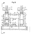
- Fig.13 shows an ensemble front view of a plant with two pre-pressing groups and one final pressing group in intermediate position according to a third example;
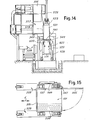
- Fig.14 shows a schematic view from line XIV-XIV of Fig.13; and
- Fig.15 shows a very rough, local section according to the line XV-XV of Fig.13.
- According to what is shown in Figs.1 to 3,
number 1 indicates the base of a first pressing group having aportal 3, which is associated with means for the loading of the material generally indicated by 5, of a per se traditional type for loading the material in a room or space where it is to be repeatedly compressed. To this end, the pre-pressing group presents a room, for receiving the material to be pressed, defined by alower surface 7, two fixedopposite side walls 9 which define said room together with apusher 10 operated by anactuator system 12 which acts in the horizontal direction according to f10; at the opposite side of the pusher 10 a secondretaining wall 14 is provided which is intended to be moved to carry out the transfer; by way of example, this wall is moved in its own plane according to arrow f14, but it might be also removed in another suitable manner.Number 16 indicates the pressing system of said first pre-pressing group, able to operate with itsown presser 16A in the well of the containing room of said first group. -
Number 18 indicates the base of a second group for final pressing, whose portal is indicated by 20, some components of which may be in common with those ofportal 3.Number .22 indicates the base or lower fixed plane of the final press,number 24 the mobile plane of the final press andnumber 26 indicates the power system for said final pressing group. With the above described final pressing system, a binding system and, possibly, also a wrapping system is associated, both per se known for these purposes in the traditional presses for textile materials; in particular, the bale-wrapping film may be developed into two sections which are laid against the opposite active surfaces of thestationary plane 22 and of themobile plane 24, the films being possibly fed from corresponding coil-shaped tanks. The wrapping up of the pressed bale by said films is carried out just before the binding which, thereby, retains as well the protection envelope formed by said films. All these solutions are per se known and require some space around the pressing zone of the final pressing group. - The pressing plant is completed by an apparatus for the transfer of partially pressed material from the first pressing group up to the second group of final pressing. According to the schema of the drawing, the transfer is operated by a movement according to arrows fT shown in Figs.2 and 3, and to this purpose,
rails 30 may be provided, roughly shown in Figs.1 and 3, and developing in front of the two groups. On these rails acarriage 32 which makes part of the transfer apparatus slides. The carriage has a pair of horizontal, spaced apart, facingwalls pusher shaped walls walls pusher 10. On thecarriage 32 and between the bars-shaped walls 34, 36 apusher 38 develops, driven by anactuator 40 for a movement according to f38 and in opposite direction. In the illustrated embodiment, thewall 14 also develops between the two facing bars-shaped walls - By the
loading system 5 the material is put into the well delimited by thelower wall 7, theretaining wall 14, the wall ofpusher 10 and the two fixedwalls 9; by means ofsystem carriage 32 in front of the first pre-pressing group, thewall 14 is made to slide according to f14 in order to defile it from the mass or bulk M, and theactuator 12 of thepusher 10 is operated to cause a translation, according to f10, of the partially pressed material M to insert it between the two bars-shaped walls pusher 38 being drawn . back. The sliding operated by thepusher 10 is made easier in that the twoopposite walls opposite walls carriage 32 according to arrow fT to take it from the position in front of the first pre-pressing group up to the position in front of the second group of final pressing, that is, in alignment with thefixed bottom wall 22. - When the
carriage 32 is in front of the second group of final pressing which includes thepressing walls pusher 38 is moved by theactuator 40 according to arrow f38 until the bulk of the partially pressed material is introduced between the twowalls opposite walls carriage 32. Under these conditions the final pressing is operated by thesystem 26, without any retaining wall as the material is compacted enough for carrying out its final pressing without any trend to widening. - After the final pressing has been performed the final wrapping and binding operations are carried out. It should be noted that the plastic film, if any, for the wrapping of the bale - which film is laid against the active surfaces of the
pressing walls 22 and 24 - helps the sliding of the partially pressed material M, owing to the limited friction that these films present over the sliding of the material, whereas these films have not, practically, the tendency to slide respect to the surfaces of thepressing walls - The
pusher 40 might also be in a fixed position in front of the final-pressing group. - In the embodiment of Figs.4 to 6, the corresponding members are indicated by the same references. In this embodiment the
wall 14 is lacking, and in its place two grid-like walls walls walls retaining walls 9 of said group. The two articulatedwalls shaped walls shaped wall 134 is lowered down until it rests on afixed pawl 142 and the bars-shaped wall 136 is raised until it abuts against an upper fixedpawl 144. The twopawls portal structure 120 making part of the second group of final pressing, which is located - rather than side by side as in the previous instance - opposite that is facing in the direction of arrow f10 and spaced to a limited degree respect to the first group formed by theportal structure group opposite walls second group 120 for the final pressing. - In this instance, the
retaining wall 14 may be replaced directly by the bars of the two angularlymovable walls second group 120, the bars-shaped walls push system 110, 112 - equivalent to the one indicated by 10 but with a . longer run - pushes the partially pressed material to slide it along the bars-shaped walls pressing walls pressing group 120, which correspond to thewalls - It is not excluded to utilize - in an arrangement like that of Figs.4 and 5 - a retaining mobile wall similar to that designated by 14 and to provide slide walls like those designated by 134 and 136 otherwise movable rather than by rotation, with the purpose to clear the space around the
group 120 for the wrapping operation of the pressed bale and the binding of the same bale. - In the embodiment shown in Figs.7 and 8, the members, fully equivalent to those described in the preceding embodiments are designated by the same references and are not, therefore, further described in detail. According to this embodiment, a first pressing group is provided with a presser 116A (corresponding to the one indicated by 16A) having channels 116B relatively deep and oriented in the direction of the removal of the material block partially pressed therein. Also the
lower contrast surface 107 of the pre-pressing group is realized with channels . 107B similar to those indicated by 116B. Moreover, thelower contrast surface 107 of the pre-pressing group is made movable through a lower cylinder-piston system 108 which allows limited displacements. The pressing space of the pre-pressing group is defined, besides by the twosurfaces 116A and 107, by a fixedwall 111 and twoopposite walls 112 which are movable and, in particular, - according to the drawing - are articulated on top at 114 to be moved away, to some extent, the one from the other and from thelower surface 107. The front opposite to thewall 111 is closed - during the loading and the pre-pressing operations - by amobile wall 120 of a pusher driven by asystem 122 which has, in part, the function ofsystem pusher carriage structure 124 which can be moved according to arrow f124 and in opposite direction towards and from the pre-pressing zone delimited by thewalls pusher rails 126 which, in turn, are formed on acarriage 128 which is to be moved alongrails 130 substantially corresponding to those indicated by 30 of the firstly illustrated example. Thecarriage 128 may be moved (likewise the one indicated by 32, previously described) between the position in front of the pre-pressing . system and the position in front of the final pressing system, which includes themobile walls carriage 124 forms anupper fork 224 and alower fork 324 which are able to fit into the channels 116B and respectively 107B, when thesurfaces 116A and 107 are in the position of maximum approach for the final-pressing stage. - When a pre-pressing cycle is to be carried out, the
surface 107 is lifted from thesystem 108 to the position in which thechannels 107B result lined up with thelower fork 324. Thecarriage 124 finds itself in a position with theforks 324 being outside and lined up with thechannels 107B. Themobile wall 120 of thepusher carriage 124 is shifted to the position indicated by 120X in which saidwall 120 completes the loading tank or box further formed by thewalls 112 brought close to one another, by thesurface 107 and thewall 110 opposite to thewall 120. Under these conditions, the loading and the successive stages for the pre-pressing of the material by thesystems 16 and 116A are carried out. At the end of the pre-pressing stage, the surface 116A finds itself lowered in such a way as to present its channels 1163 in alignment with theupper fork 224. Under these conditions, thecarriage 124 is caused to advance according to arrow f124, while thewall 120 is kept stationary, this wall withdrawing - relative to the advancing carriage. The
forks wall 107 is lowered and the wall 116A is lifted so that the material which has been subjected to the pre-pressing operation will come in contrast withforks walls 112 are moved apart; thecarriage 124 is moved in the direction opposite to the one indicated by arrow f124; the bulk of the preliminarily pressed material which is between the twoforks carriage 128, bearing theguides 126 of thecarriage 124, is moved from the position in front of the pre-pressing zone up to the position in front of the final press, that is, in alignment withwalls walls forks pressing planes push system walls forks - According to Figs.9 to 12 there is provided a first pressing group with
feeder 1005, apresser deep channels 1116B oriented in the direction of the withdrawing of the material block partially pressed therein, alower surface 1107 of contrast for the pre-pressing group, this surface being also realized withchannels 1107B similar to those indicated by 1116B; saidlower contrast surface 1107 of the pre-pressing group is movable through a lower cylinder-piston system 1108 which allows limited displacements. The pressing space of the pre-pressing group is defined, besides by the twosurfaces wall 1111 and twoopposite walls 1112 which are movable and, in particular - according to the drawing - articulated on top at 1114 so that they can be moved, to a limited extent, away from one another and from thelower surface 1107. The front opposite towall 1111 is closed - during the loading and the pre--pressing operations - by awall 1118 which can be defiled that is shifted, by a sliding on its plane or otherwise removed. By 1120 a mobile wall is indicated of a pusher operated by asystem 1122. Thepusher carriage structure 1124 which can be moved, according toarrow 1124 and in opposite direction, towards and from the pre-pressing zone delimited by thewalls 1110 and 1112, parallel to the direction of displacement ofpusher rails 1126 which are, in turn, formed on acarriage 1128 which is intended to be moved along therails 1130. Thecarriage 1128 can be moved between the position in front of the pre-pressing system and the position in front of the final pressing system, which comprises themobile walls group 1026 on theframe 1020. Thecarriage 1124 forms anupper fork 1224 and alower fork 1324 which are apt to fit intochannels 1116B and respectively 1107B when thesurfaces - The
mobile wall 1120 of thepusher stems bars 1224 and between the ones indicated by .1324 at an intermediate level relative to them. Said stems have a very smooth surface, being for example chromium plated, and are of very limited dimensions being able to be, for example, rod-shaped; they are not required to be particularly resistant to stresses by the pressed material. The purpose of thesestems - When a pre-pressing cycle is to be carried out, the
surface 1107 is lifted from thesystem 1108 to a position in which thechannels 1107B result lined up with thelower fork 1324. Thecarriage 1124 finds itself in a position with theforks 1324 outside of and lined up with thechannels 1107B. Themobile wall 1120 of thepusher carriage 1124 is, in this case, kept in back position, and the saidshifting wall 1118 is provided, in order to complete the loading tank being further formed bywalls 1112, drawn close to one another, by thesurface 1107 and the wall 1110. Under these conditions, the loading and the subsequent stages of pre-pressing of the material bysystems surface 1116A is lowered in such a way as to present itschannels 1116B in alignment with theupper fork 1224. Under these conditions, thewall 1118 is moved away and thecarriage 1124 is caused to advance according toarrow 1124, together withwall 1120 with stems.1420 and 1430. Theforks 1224 and 1324 (as well as stems 1420 and 1430) fit into thechannels wall 1107B is lowered and thewall 1116A is raised so that the material, which has been subjected to the pre-pressing operation, will come to contrast onforks walls 1112 are moved away from each other and thecarriage 1124 is moved in the direction opposite to the one indicated by arrow f1124; the bulk of the preliminarily pressed material which is between the twoforks carriage 1128 which bears theguides 1126 of carriage, 1124, is shifted from the position in front of the pressing group up to the position in front of the final press, that is in alignment with thewalls walls forks pressing planes thrust system walls forks -
Stems bars pusher 1120, come in alignment and slightly inwardly of the active surfaces of the final-pressingwalls carriage 1124 has been brought in front of the final pressing station. Under these conditions, by keeping thecarriage 1124 in rear position and causing thepusher 1120 to advance through thesystem 1122, the bulk of the partially pressed material is caused to advance together with stems 1420, 1430. During the advancement, the partially pressed bulk reacts without solution of continuity progressively lesser and lesser onbars walls walls pusher 1120, the stems 1420, 1430 result interposed between the bulk of material M and thewalls stems pusher 1120. When the bulk M has reached the position of final pressing between the twowalls pusher 1120 is drawr back and thestems pusher 1120 and stems 1420, 1430, thesystem 1026 of final pressing may be put into operation. - According to Figs.13 to 15,
number 501 indicates a central housing for a final-pressing group, and abase 503 and amobile wall 505 of this group are visible, saidwall 503 being apt to be drawn near the base 503 by means of a hydraulic or equivalent power-system 507. Thebase 503 and themobile wall 505 are realized with channels to permit the binding of the bale of pressed material after completion of the pressing and of a possible wrapping by envelope-forming films. The binding is effected by abinding unit 509 of a type per se known, in one or more stages. At the two sides of thehousing 501 two pre-pressing groups, generally indicated by 511 and 513 are disposed, each of which includes a feeding system with a mechanical orpneumatic conveyor 515, astorage tank 517 and apusher 519 able to push the material from thetank 517 to adrop room 521 overhanging a filling and pre-pressing space. The filling and the pre-pressing are carried out with the aid of apresser 523 alternatively movable through the control of cylinder--piston systems 525 in order to preliminarily tamp and press - by a plurality of lowering and lifting cycles - the material in said filling and pressing space. - The filling and pressing space for each of the two
groups carriage drop room 521 up to a position below themobile wall 505, each carriage being able to slide just above thebase 503 by resting and sliding on guides disposed at the sides thereof. Each carriage, like the one indicated by 529 to be descri bed below, has one horizontallower diaphragm 531, which can be made to slide by means of suitable fluid--operated control means 533 or the like for a movement along its own plane. The carriage also includes three vertical fixed walls of which one indicated by 535 is transversal and the other two indicated by 537, 539 are longitudinal relative to the direction of the carriage movement which is indicated by the double arrow f in the drawing. On the top of the threevertical walls pre-pressing tank 521, a second horizontalupper diaphragm 541 is provided which may consist of a single structure or of two parts separately movable. Also said diaphragm 541 - which may be formed by two movable parts - may be moved along its own plane through suitable fluid-operated or equivalent control means 543. In thewalls 539 two sets of slots are formed for the introduction therein ofcombs 600, which have the function of retaining the material during the spring back phase when thebox piston systems 602. Theupper combs 600 and the threewalls mobile wall 545 vertically hinged at 547 to the wall 537 (see Fig.13) in order to be opened and respectively closed (as far as it comes in contact with the wall 539) so as to define said filling and pressing space. In each carriage, themobile wall 545 is the inner one facing the second group, centrally located, for the final pressing. Also the opening and closing of themobile wall 545 is controlled by a fluid-operated or equivalent control means 549. - The plant summarily described with reference to Figs.13 to 15 operates as follows. Each carriage is brought under the
drop room 521 of its own pre-pressing group in 'such a condition as to define the filling and pressing space, with thediaphragm 531 and thewalls mobile wall 545 in the closing arrangement. In these conditions,.the filling of this space takes place in the usual way, with subsequent cycles of drop discharge and of preliminary pressing by thepresser 523. Retaining means may be predisposed for retaining the partially pressed material between one lowering cycle and another of thepresser 523, in order to avoid the pro- gressive swelling of the material. At the end of the pre-pressing operation, in the space defined on the carriage, as described above, the combs 600 - which retain the material - are put into,an active position, theupper diaphragm 541 is closed and the carriage is transferred to the second group of final pressing until thelower diaphragm 531 is brought just below thebase 503 and the upper combs are brought just below themobile wall 505; in the meantime the drop of the material into theroom 521 of the pre-pressing group is not interrupted. The pressing group starts its action while the twodiaphragms walls mobile wall 505. A film intended to form envelope is possibly already available on thebase 503 and under thewall 505, so as to form an envelope or wrapping after the pressing. The intervention of the binding unit completes the packaging. In order to operate - after the final pressing - the possible formation of the envelope and, anyway, the binding, thewall 545 is opened and the carriage is moved away in the direction opposite to the one according which it has transferred the material under the group of final pressing; for this moving away of the carriage thewalls - The operations performed by the two
carriages - The
combs 600 and the pressing means may be realized in such a way as to avoid mutual interferences. - Whatever the construction may be chosen, there is obtained a plant of limited extension in height and, therefore, capable of being installed without any costly partial laying underground of the structures. The construe tion of the group results much simpler and thus far more economical and of much more limited overall dimensions which increases its economy also as far as the required space is concerned. These and other objects and advantages will result apparent to those skilled in the art from a reading of the preceding description.
- It is understood that the drawing shows some exempli fications given only as practical demonstrations of the invention which may vary in the forms and dispositions without nevertheless coming out from the ambit of the idea on which the invention itself is based. The possible presence of reference numbers in the attached claims has the purpose to facilitate the reading of the claims, reference being made to the description and drawing, and is not, therefore, aimed to put limitations to the ambit of the protection pointed out by the claims.
Claims (18)
Applications Claiming Priority (6)
| Application Number | Priority Date | Filing Date | Title |
|---|---|---|---|
| IT09346/85A IT1201240B (en) | 1985-02-22 | 1985-02-22 | Textile baling press |
| IT934685 | 1985-02-22 | ||
| IT940985 | 1985-05-14 | ||
| IT09409/85A IT1201292B (en) | 1985-05-14 | 1985-05-14 | Textile baling press |
| IT947785 | 1985-08-20 | ||
| IT8509477A IT1214914B (en) | 1985-08-20 | 1985-08-20 | Textile baling press |
Publications (2)
| Publication Number | Publication Date |
|---|---|
| EP0198992A1 true EP0198992A1 (en) | 1986-10-29 |
| EP0198992B1 EP0198992B1 (en) | 1989-02-08 |
Family
ID=27272730
Family Applications (1)
| Application Number | Title | Priority Date | Filing Date |
|---|---|---|---|
| EP19850830259 Expired EP0198992B1 (en) | 1985-02-22 | 1985-10-14 | Two-stage baler |
Country Status (3)
| Country | Link |
|---|---|
| EP (1) | EP0198992B1 (en) |
| DE (1) | DE3568152D1 (en) |
| ES (1) | ES8701602A1 (en) |
Cited By (16)
| Publication number | Priority date | Publication date | Assignee | Title |
|---|---|---|---|---|
| EP0252587A1 (en) * | 1986-07-09 | 1988-01-13 | Ngk Insulators, Ltd. | Compression and volume reduction treatment apparatus |
| EP0441753A1 (en) * | 1990-02-06 | 1991-08-14 | GUALCHIERANI SYSTEM s.a.s. di Sergio Gualchierani & C. | Apparatus for the pressing and packing of bumps |
| US5687643A (en) * | 1996-01-16 | 1997-11-18 | Felts; J. David | Method and apparatus for producing a strapped bale of compressed fibers |
| WO2000038908A1 (en) * | 1998-12-29 | 2000-07-06 | Tiziano Bielli | Two-station press for textile material |
| WO2002038364A1 (en) * | 2000-11-13 | 2002-05-16 | Gualchierani Textile Automation S.P.A. | Two-station press for textile material, equipped with system for wrapping the pressed material |
| WO2013030401A3 (en) * | 2011-09-02 | 2013-05-02 | Hi Tech Textile Holding Gmbh | Packaging system for pressed bales with a transporting device |
| BE1021027B1 (en) * | 2013-09-24 | 2015-01-27 | Valvan Baling Systems Nv | DOUBLE STATION BALEN PRESS DEVICE. |
| CN104812674A (en) * | 2012-05-16 | 2015-07-29 | 信诺国际Ip控股有限责任公司 | Strapless strapping method and strapping machine |
| US9655303B2 (en) | 2013-09-17 | 2017-05-23 | Signode Industrial Group Llc | Method for containing a bale of compressible material |
| US9686919B2 (en) | 2012-05-16 | 2017-06-27 | Signode Industrial Group Llc | Method for containing a bale of compressible material without straps |
| CN107415302A (en) * | 2017-05-04 | 2017-12-01 | 芜湖立新清洁用品有限公司 | A kind of mophead compression set |
| CN108891054A (en) * | 2018-07-12 | 2018-11-27 | 合肥七小俊生物科技有限公司 | One kind repeatedly squeezing extract equipment for Chinese medicine slag |
| WO2019030218A1 (en) * | 2017-08-09 | 2019-02-14 | Autefa Solutions Germany Gmbh | PACKAGING DEVICE AND PACKAGING METHOD |
| US10206333B2 (en) | 2015-05-14 | 2019-02-19 | Signode Industrial Group Llc | Compressed bale packaging apparatus with bag applicator assist device and bag for same |
| WO2020036769A1 (en) * | 2018-08-14 | 2020-02-20 | Signode Industrial Group Llc | Fibrous material baling system |
| CN110948928A (en) * | 2020-01-02 | 2020-04-03 | 成小芳 | New forms of energy fuel compressor arrangement |
Citations (4)
| Publication number | Priority date | Publication date | Assignee | Title |
|---|---|---|---|---|
| DE2819807A1 (en) * | 1977-05-05 | 1978-11-16 | Sunds Ab | METHOD AND DEVICE FOR FORMING VOLUMINOUS MATERIAL TO BALE BY PRESSING AND BINDING |
| DE2911958A1 (en) * | 1979-03-27 | 1980-10-16 | Hoechst Ag | METHOD FOR PACKAGING FIBROUS GOODS IN BALES AND SUITABLE PRESSING SYSTEM THEREFOR |
| US4343131A (en) * | 1980-05-02 | 1982-08-10 | Ea Industries, Incorporated | Method and apparatus for producing bales |
| US4476779A (en) * | 1978-10-03 | 1984-10-16 | Tezuka Kosan Kabushiki Kaisha | Compression bundling apparatus |
-
1985
- 1985-10-14 DE DE8585830259T patent/DE3568152D1/en not_active Expired
- 1985-10-14 EP EP19850830259 patent/EP0198992B1/en not_active Expired
- 1985-10-29 ES ES548299A patent/ES8701602A1/en not_active Expired
Patent Citations (4)
| Publication number | Priority date | Publication date | Assignee | Title |
|---|---|---|---|---|
| DE2819807A1 (en) * | 1977-05-05 | 1978-11-16 | Sunds Ab | METHOD AND DEVICE FOR FORMING VOLUMINOUS MATERIAL TO BALE BY PRESSING AND BINDING |
| US4476779A (en) * | 1978-10-03 | 1984-10-16 | Tezuka Kosan Kabushiki Kaisha | Compression bundling apparatus |
| DE2911958A1 (en) * | 1979-03-27 | 1980-10-16 | Hoechst Ag | METHOD FOR PACKAGING FIBROUS GOODS IN BALES AND SUITABLE PRESSING SYSTEM THEREFOR |
| US4343131A (en) * | 1980-05-02 | 1982-08-10 | Ea Industries, Incorporated | Method and apparatus for producing bales |
Cited By (28)
| Publication number | Priority date | Publication date | Assignee | Title |
|---|---|---|---|---|
| EP0252587A1 (en) * | 1986-07-09 | 1988-01-13 | Ngk Insulators, Ltd. | Compression and volume reduction treatment apparatus |
| US4760783A (en) * | 1986-07-09 | 1988-08-02 | Ngk Insulators, Ltd. | Compression apparatus having a main compression device and a tapered precompression device |
| EP0441753A1 (en) * | 1990-02-06 | 1991-08-14 | GUALCHIERANI SYSTEM s.a.s. di Sergio Gualchierani & C. | Apparatus for the pressing and packing of bumps |
| US5687643A (en) * | 1996-01-16 | 1997-11-18 | Felts; J. David | Method and apparatus for producing a strapped bale of compressed fibers |
| WO2000038908A1 (en) * | 1998-12-29 | 2000-07-06 | Tiziano Bielli | Two-station press for textile material |
| KR100500629B1 (en) * | 1998-12-29 | 2005-07-12 | 비엘리 티지아노 | Two-station press for textile material |
| US7055424B1 (en) | 1998-12-29 | 2006-06-06 | Tiziano Bielli | Two-station press for textile material |
| WO2002038364A1 (en) * | 2000-11-13 | 2002-05-16 | Gualchierani Textile Automation S.P.A. | Two-station press for textile material, equipped with system for wrapping the pressed material |
| US9650166B2 (en) | 2011-09-02 | 2017-05-16 | Hi Tech Textile Holding Gmbh | Transporting device for pressed bales |
| CN103889841B (en) * | 2011-09-02 | 2016-03-16 | 恒天(奥地利)控股有限公司 | For the packaging system with transportation device of compressed bales |
| CN103889841A (en) * | 2011-09-02 | 2014-06-25 | 恒天(奥地利)控股有限公司 | Transporting device for pressed bales |
| WO2013030401A3 (en) * | 2011-09-02 | 2013-05-02 | Hi Tech Textile Holding Gmbh | Packaging system for pressed bales with a transporting device |
| US9686919B2 (en) | 2012-05-16 | 2017-06-27 | Signode Industrial Group Llc | Method for containing a bale of compressible material without straps |
| CN104812674A (en) * | 2012-05-16 | 2015-07-29 | 信诺国际Ip控股有限责任公司 | Strapless strapping method and strapping machine |
| US9656775B2 (en) | 2012-05-16 | 2017-05-23 | Signode Industrial Group Llc | Strap-less baling method and baler |
| CN104812674B (en) * | 2012-05-16 | 2017-07-28 | 信诺国际Ip控股有限责任公司 | Strapless strapping method and strapping machine |
| US9655303B2 (en) | 2013-09-17 | 2017-05-23 | Signode Industrial Group Llc | Method for containing a bale of compressible material |
| EP2853385A1 (en) | 2013-09-24 | 2015-04-01 | Valvan Baling Systems NV | Dual-station baler device |
| BE1021027B1 (en) * | 2013-09-24 | 2015-01-27 | Valvan Baling Systems Nv | DOUBLE STATION BALEN PRESS DEVICE. |
| US10206333B2 (en) | 2015-05-14 | 2019-02-19 | Signode Industrial Group Llc | Compressed bale packaging apparatus with bag applicator assist device and bag for same |
| CN107415302A (en) * | 2017-05-04 | 2017-12-01 | 芜湖立新清洁用品有限公司 | A kind of mophead compression set |
| CN107415302B (en) * | 2017-05-04 | 2024-02-02 | 芜湖立新清洁用品有限公司 | Mop head compression device |
| WO2019030218A1 (en) * | 2017-08-09 | 2019-02-14 | Autefa Solutions Germany Gmbh | PACKAGING DEVICE AND PACKAGING METHOD |
| US11305901B2 (en) | 2017-08-09 | 2022-04-19 | Autefa Solutions Germany Gmbh | Packaging device and packaging process |
| CN108891054A (en) * | 2018-07-12 | 2018-11-27 | 合肥七小俊生物科技有限公司 | One kind repeatedly squeezing extract equipment for Chinese medicine slag |
| WO2020036769A1 (en) * | 2018-08-14 | 2020-02-20 | Signode Industrial Group Llc | Fibrous material baling system |
| CN110948928A (en) * | 2020-01-02 | 2020-04-03 | 成小芳 | New forms of energy fuel compressor arrangement |
| CN110948928B (en) * | 2020-01-02 | 2021-12-03 | 成小芳 | New forms of energy fuel compressor arrangement |
Also Published As
| Publication number | Publication date |
|---|---|
| ES548299A0 (en) | 1986-12-16 |
| EP0198992B1 (en) | 1989-02-08 |
| DE3568152D1 (en) | 1989-03-16 |
| ES8701602A1 (en) | 1986-12-16 |
Similar Documents
| Publication | Publication Date | Title |
|---|---|---|
| EP0198992A1 (en) | Two-stage baler | |
| US5687643A (en) | Method and apparatus for producing a strapped bale of compressed fibers | |
| CN1209237C (en) | Two-station baler for textile materials | |
| US3735561A (en) | Carton packing device | |
| AU586506B2 (en) | Cheese press | |
| US4343131A (en) | Method and apparatus for producing bales | |
| CA2165339C (en) | Device for pressing | |
| CA1302226C (en) | Method and apparatus for packaging fibrous material | |
| US3824758A (en) | Method and apparatus for packing compressible material such as tobacco | |
| US2938315A (en) | Method and apparatus for packing fruit | |
| CA1203784A (en) | Method and device for packaging of soft packages | |
| CN213036154U (en) | Tobacco leaf packing apparatus | |
| US3805689A (en) | Automatic hoop filling unit | |
| US3107793A (en) | Machine for handling packages | |
| US4299074A (en) | Method and apparatus for compressing voluminous material easy to compress | |
| CN209949913U (en) | High-efficient square bundle bundling machine | |
| CN108910131B (en) | Horizontal tobacco shred boxing system and method | |
| US4360997A (en) | Baling apparatus and method | |
| US3614850A (en) | Method for packaging loose fibrous material from a continuous flow | |
| US3796150A (en) | Apparatus for baling fibers and the like | |
| US4041855A (en) | Opposed box baling press | |
| EP0222815A1 (en) | Method and apparatus for manufacturing bales of voluminous fibre material | |
| US2370791A (en) | Method of packing cigars | |
| CN111204498A (en) | Material packaging device and method | |
| CN222572752U (en) | Raw cigarette vanning system of parallel |
Legal Events
| Date | Code | Title | Description |
|---|---|---|---|
| PUAI | Public reference made under article 153(3) epc to a published international application that has entered the european phase |
Free format text: ORIGINAL CODE: 0009012 |
|
| AK | Designated contracting states |
Kind code of ref document: A1 Designated state(s): BE DE FR GB |
|
| 17P | Request for examination filed |
Effective date: 19860926 |
|
| 17Q | First examination report despatched |
Effective date: 19871102 |
|
| RAP1 | Party data changed (applicant data changed or rights of an application transferred) |
Owner name: GUALCHIERANI SYSTEM S.A.S. DI SERGIO GUALCHIERANI |
|
| GRAA | (expected) grant |
Free format text: ORIGINAL CODE: 0009210 |
|
| AK | Designated contracting states |
Kind code of ref document: B1 Designated state(s): BE DE FR GB |
|
| REF | Corresponds to: |
Ref document number: 3568152 Country of ref document: DE Date of ref document: 19890316 |
|
| ET | Fr: translation filed | ||
| PLBE | No opposition filed within time limit |
Free format text: ORIGINAL CODE: 0009261 |
|
| STAA | Information on the status of an ep patent application or granted ep patent |
Free format text: STATUS: NO OPPOSITION FILED WITHIN TIME LIMIT |
|
| 26N | No opposition filed | ||
| PGFP | Annual fee paid to national office [announced via postgrant information from national office to epo] |
Ref country code: FR Payment date: 19940930 Year of fee payment: 10 |
|
| PGFP | Annual fee paid to national office [announced via postgrant information from national office to epo] |
Ref country code: GB Payment date: 19941004 Year of fee payment: 10 |
|
| PGFP | Annual fee paid to national office [announced via postgrant information from national office to epo] |
Ref country code: BE Payment date: 19941012 Year of fee payment: 10 |
|
| PGFP | Annual fee paid to national office [announced via postgrant information from national office to epo] |
Ref country code: DE Payment date: 19941223 Year of fee payment: 10 |
|
| PG25 | Lapsed in a contracting state [announced via postgrant information from national office to epo] |
Ref country code: GB Effective date: 19951014 |
|
| PG25 | Lapsed in a contracting state [announced via postgrant information from national office to epo] |
Ref country code: BE Effective date: 19951031 |
|
| BERE | Be: lapsed |
Owner name: GUALCHIERANI SYSTEM S.A.S. DI SERGIO GUALCHIERANI Effective date: 19951031 |
|
| GBPC | Gb: european patent ceased through non-payment of renewal fee |
Effective date: 19951014 |
|
| PG25 | Lapsed in a contracting state [announced via postgrant information from national office to epo] |
Ref country code: FR Effective date: 19960628 |
|
| PG25 | Lapsed in a contracting state [announced via postgrant information from national office to epo] |
Ref country code: DE Effective date: 19960702 |
|
| REG | Reference to a national code |
Ref country code: FR Ref legal event code: ST |