EP0199040A1 - Schlagbohrkrone für Gesteinsbohrmaschinen - Google Patents
Schlagbohrkrone für Gesteinsbohrmaschinen Download PDFInfo
- Publication number
- EP0199040A1 EP0199040A1 EP86103129A EP86103129A EP0199040A1 EP 0199040 A1 EP0199040 A1 EP 0199040A1 EP 86103129 A EP86103129 A EP 86103129A EP 86103129 A EP86103129 A EP 86103129A EP 0199040 A1 EP0199040 A1 EP 0199040A1
- Authority
- EP
- European Patent Office
- Prior art keywords
- drill bit
- face
- bit according
- channels
- pins
- Prior art date
- Legal status (The legal status is an assumption and is not a legal conclusion. Google has not performed a legal analysis and makes no representation as to the accuracy of the status listed.)
- Granted
Links
- 238000009527 percussion Methods 0.000 title claims abstract description 17
- 239000011435 rock Substances 0.000 title claims abstract description 9
- 239000012530 fluid Substances 0.000 claims abstract description 24
- 238000005553 drilling Methods 0.000 claims abstract description 12
- 239000002184 metal Substances 0.000 claims abstract description 5
- 238000005520 cutting process Methods 0.000 claims description 16
- 230000007704 transition Effects 0.000 claims description 4
- 210000004283 incisor Anatomy 0.000 claims description 3
- 230000036346 tooth eruption Effects 0.000 claims description 3
- 239000007789 gas Substances 0.000 description 5
- 230000018109 developmental process Effects 0.000 description 2
- 230000009286 beneficial effect Effects 0.000 description 1
- 238000005265 energy consumption Methods 0.000 description 1
- 239000000463 material Substances 0.000 description 1
Images


Classifications
-
- E—FIXED CONSTRUCTIONS
- E21—EARTH OR ROCK DRILLING; MINING
- E21B—EARTH OR ROCK DRILLING; OBTAINING OIL, GAS, WATER, SOLUBLE OR MELTABLE MATERIALS OR A SLURRY OF MINERALS FROM WELLS
- E21B10/00—Drill bits
- E21B10/36—Percussion drill bits
- E21B10/38—Percussion drill bits characterised by conduits or nozzles for drilling fluids
-
- E—FIXED CONSTRUCTIONS
- E21—EARTH OR ROCK DRILLING; MINING
- E21B—EARTH OR ROCK DRILLING; OBTAINING OIL, GAS, WATER, SOLUBLE OR MELTABLE MATERIALS OR A SLURRY OF MINERALS FROM WELLS
- E21B10/00—Drill bits
- E21B10/003—Drill bits with cutting edges facing in opposite axial directions
-
- E—FIXED CONSTRUCTIONS
- E21—EARTH OR ROCK DRILLING; MINING
- E21B—EARTH OR ROCK DRILLING; OBTAINING OIL, GAS, WATER, SOLUBLE OR MELTABLE MATERIALS OR A SLURRY OF MINERALS FROM WELLS
- E21B10/00—Drill bits
- E21B10/46—Drill bits characterised by wear resisting parts, e.g. diamond inserts
- E21B10/56—Button-type inserts
Definitions
- the invention relates to a percussion drill bit for rock drilling machines, the end face of which is covered with a large number of hard metal pins, several pins being combined to form a group, the groups thus formed being at least circumferentially spaced from one another and being separated from one another by fluid channels, and also as a fluid outlet at least one axial channel opening into the channels is provided, for example in the central region of the end face.
- Such a drill bit is known for example from DE-OS 27 33 300.
- two-part drill bit, cutting inserts for example in the form of hard metal pins, are provided in groups, the groups being spaced apart from one another by means of fluid channels which run radially or are slightly curved in the direction of rotation.
- the pins are arranged in a multiple arrangement on an island protruding from the fluid channels, so that larger chunks of cuttings can settle between the pins, which leads to a relatively long drilling time with appropriate propulsion, since these chunks first have to be ground down before they can pass through the fluid channels can be discharged to the outside through the fluid.
- the fluid channels serve to guide the exhaust gas and do not support the removal of the cuttings, which removal is only caused by the exhaust gas.
- the invention has for its object to provide a hammer drill bit of the type mentioned, in which on the one hand there is a relatively simple possibility for regrinding, but on the other hand largely prevents larger chunks of cuttings between the pins and prevents the removal of the Bohrkleins promotes.
- the groups each consist only of a series of pins which are arranged on molded webs.
- the webs are curved.
- the fluid channels formed in the end face are designed to widen radially outward from the center of the crown.
- the end face is curved.
- channels are formed axially in the transition region between the end face and the shaft, into which channels the fluid channels of the end face open.
- the arrangement of axially extending channels in the transition region between the end face and the shaft is known, for example from DE-OS 26 33 779.
- the special arrangement of the channels is particularly advantageous since there is now excellent transport between the channels in the end face and the axially extending channels.
- the axial channels be displaced far into the crown body, partially crossing the front fluid channels and possibly partially crossing the webs.
- the design according to the invention brings a higher performance without greater wear, so that the same drilling depth is achieved in a shorter time with less wear than is possible in the prior art. There is also less stress on the pins.
- the better grindability of the pins, in particular with simple means, is also advantageous, with the arrangement of the pins providing the cut as possible on the flanks of the pins that lie on the web side edges.
- cut-back teeth pointing axially away from the end face are integrally formed between the axial channels.
- the rear incisors are arranged on a crown base which tapers laterally and radially inwards away from the end face.
- each web is arranged on a crown part formed by a cutting tooth.
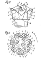
- a percussion drill bit is shown, which is provided with a grooved shaft (not shown), so that each is a left-handed embodiment.
- the direction of rotation is indicated by the arrow A in FIGS. 2, 4 and 6.
- the percussion drill bit for rock drilling machines has a plurality of hard metal pins 1 in the end face, several pins 1 being combined to form a group of pins. These groups are spaced from each other. They are spatially separated from one another by fluid channels.
- An axial channel 3 opening into the channels 2 is provided as the fluid outlet for the exhaust gases of the drilling machine, approximately in the central region of the end face.
- the groups referred to below are each formed only from a series of pins 1 which are fastened on molded webs 4.
- the webs 4 are arranged inclined to the radius against the direction of rotation A of the drill bit.
- the simplest embodiment is shown in Figures 1 and 2.
- the webs 4 and the fluid channels 2 are both curved, the curvature running counter to the direction of rotation A of the drill bit.
- the fluid channels 2 formed in the end face expand considerably radially outward from the center of the crown.
- the end face of the percussion drill bit is designed in the shape of a truncated cone, whereas the end face in the exemplary embodiments according to FIGS. 3 to 6 is bulged outwards.
- axially extending channels 6 are arranged in the transition area between the end face and shaft 5, into which the fluid channels 2 open.
- the axial channels 6 are shifted as far as possible into the body of the drill bit, partly crossing the fluid channels 2 on the face side and partly also the webs 4 (in particular in the embodiment according to FIGS. 5 + 6).
- cut-back teeth 7 are formed between the axial channels 6 on the outside axially pointing away from the end face.
- the rear incisors 7 are arranged on a crown base 8 tapering laterally and radially inward away from the end face.
- the radially outermost pin of each web 4 is arranged on a crown part formed by a cutting tooth 7.
- Two pins 1 are preferably arranged on each web 4. Depending on the course and arrangement of the webs, it can also be advantageous to arrange three pins 1 or only one pin 1 on a web 4.
- the design according to the invention achieves a high drilling performance with relatively little wear, as well as a long service life of the drill bit with low energy consumption, since the cuttings leave the bottom of the borehole much coarser.
- the invention is not limited to the exemplary embodiments, but is often variable within the scope of the disclosure.
Landscapes
- Engineering & Computer Science (AREA)
- Geology (AREA)
- Mining & Mineral Resources (AREA)
- Life Sciences & Earth Sciences (AREA)
- General Life Sciences & Earth Sciences (AREA)
- Fluid Mechanics (AREA)
- Environmental & Geological Engineering (AREA)
- Physics & Mathematics (AREA)
- Mechanical Engineering (AREA)
- Geochemistry & Mineralogy (AREA)
- Earth Drilling (AREA)
- Drilling Tools (AREA)
- Orthopedics, Nursing, And Contraception (AREA)
- Processing Of Stones Or Stones Resemblance Materials (AREA)
- Percussive Tools And Related Accessories (AREA)
- Dental Tools And Instruments Or Auxiliary Dental Instruments (AREA)
Abstract
Description
- Die Erfindung betrifft eine Schlagbohrkrone für Gesteinsbohrmaschinen, deren Stirnfläche mit einer Vielzahl von Hartmetall-Stiften besetzt ist, wobei jeweils mehrere Stifte zu einer Gruppe zusammengefügt sind, die so gebildeten Gruppen mindestens in Umfangsrichtung Abstand voneinander aufweisen und durch Strömungsmittelkanäle voneinander getrennt sind, ferner als Strömungsmittelaustritt etwa im Mittelbereich der Stirnfläche mindestens ein in die Kanäle ausmündender Axialkanal vorgesehen ist.
- Eine derartige Bohrkrone ist beispielsweise aus der DE-OS 27 33 300 bekannt.
- Bei dieser vorbekannten, allerdings zweiteiligen Bohrkrone sind Schneideinsätze, beispielsweise in Form von Hartmetall-Stiften gruppenweise vorgesehen, wobei die Gruppen durch radial verlaufende bzw. gegebenenfalls in Drehrichtung leicht gekrümmte Strömungsmittelkanäle voneinander beabstandet sind.
- Allerdings sind die Stifte in einer Vielfachanordnung auf einer gegenüber den Strömungsmittelkanälen vorspringenden Insel angeordnet, so daß sich zwischen den Stiften größere Brocken Bohrkleins festsetzen können, was zu einer relativ langen Bohrzeit bei entsprechendem Vortrieb führt, da diese Brocken erst kleingemahlen werden müssen, bevor sie durch die Strömungsmittelkanäle durch das Strömungsmittel nach außen abgeführt werden können. Die Strömungsmittelkanäle dienen der Abgasführung und unterstützen den Abtransport des Bohrkleins nicht, welcher Abtransport lediglich durch das Abgas bewirkt wird. Darüber hinaus kann man die so angeordneten Stifte relativ schlecht nachschleifen, da die benachbarten Stifte das Nachschleifen gegenseitig behindern.
- Zur Befestigung derartiger Bohrkronen an Gesteinsbohrmaschinen ist es bei sogenannten Versenkhämmem üblich, einen genuteten Schaft in eine Aufnahme einzusetzen, wobei dann der Antrieb linksdrehend ausgeführt ist, oder aber es kann auch bei Außenlochhämmem der Schaft mit Innengewinde versehen sein, welcher dann mit einem Gewindeschaft schraubverbunden wird, wobei diese Ausführungsform dann rechtsdrehend ist.
- Aus der DE-OS 26 33 779 ist die Einzelanordnung von Stiften auf aus dem Grundkörper der Bohrkrone vorragenden Ansätzen vorbekannt, wobei diese Anordnung zwar ein leichtes Nachschleifen der Stifte ermöglicht, jedoch der Bohrkleintransport behindert ist und sich auch weiterhin größere Brocken Bohrkleins zwischen den einzelnen Stiften festsetzen können.
- Ausgehend von diesem Stand der Technik liegt der Erfindung die Aufgabe zugrunde, eine Schlagbohrkrone eingangs bezeichneter Art zu schaffen, bei der einerseits eine relative einfache Möglichkeit zum Nachschleifen gegeben ist, die aber andererseits das Festsetzen größerer Brocken Bohrkleins zwischen den Stiften weitgehend verhindert und den Abtransport des Bohrkleins fördert.
- Zur Lösung dieser Aufgabe wird vorgeschlagen, daß die Gruppen jeweils lediglich aus einer Reihe von Stiften bestehen, die auf angeformten Stegen angeordnet sind.
- Durch diese konstruktive Maßnahme ist es einerseits möglich, die Stifte einer jeden Stiftreihe relative einfach nachzuschleifen, wobei die jeweils wesentlich am Zermahlen des Gesteins beteiligten Flächen der Stifte gut zugänglich sind. Andererseits können sich zwischen den Stiften größere Brocken Bohrkleins praktisch nicht mehr festsetzen, sondem diese Brocken können sofort durch die Strömungsmittelkanäle nach radial außen abgeführt werden. Das Bohrklein -wird in die Freiräume zwischen den Stegen transportiert und durch die Auspuffgase der Gesteinsbohrmaschine, insbesondere des Bohrhammers abtransportiert.
- Besonders vorteilhaft ist, daß die Stege entgegen der Drehrichtung der Bohrkrone gegenüber dem Radius geneigt verlaufen.
- Auf diese Weise wird der Abtransport des Bohrkleins durch die Drehbewegung der Bohrkrone unterstützt, da das Bohrklein nun auch ohne die Abgase allein durch die Drehung der Bohrkrone nach radial außen gefördert wird.
- Besonders bevorzugt ist dabei, daß die Stege gekrümmt verlaufen.
- Zur weiteren Erleichterung des Abtransportes des Bohrkleins ist bevorzugt, daß die in der Stirnfläche ausgebildeten Strömungsmittelkanäle sich vom Zentrum der Krone nach radial außen erweiternd ausgebildet sind.
- Weiterhin wird vorgeschlagen, daß die Stirnfläche kegelförmig ausgebildet ist.
- Alternativ oder zusätzlich kann vorgesehen sein, daß die Stirnfläche gewölbt ist.
- In bevorzugter Weiterbildung wird vorgeschlagen, daß axial im Übergangsbereich zwischen Stirnfläche und Schaft Kanäle ausgebildet sind, in welche die Strömungsmittelkanäle der Stirnfläche münden.
- Dazu ist ansich die Anordnung von axial verlaufenden Kanälen im Übergangsbereich zwischen Stirnfläche und Schaft beispielsweise aus der DE-OS 26 33 779 bekannt. Allerdings ist die besondere Anordnung der Kanäle besonders vorteilhaft, da sich nun ein hervorragender Transport zwischen den Kanälen in der Stirnfläche und den axial verlaufenden Kanälen ergibt.
- In bevorzugter Weiterbildung wird vorgeschlagen, daß die axialen Kanäle weit in den Kronenkörper hinein verlagert sind, wobei sie teils die stirnseitigen Strömungsmittelkanäle und gegebenenfalls teils die Stege kreuzen.
- Dadurch daß die Kanäle möglichst weit nach radial innen verlegt werden, wird ein besonders schneller Abtransport des Bohrkleins gefördert. Insgesamt bringt die erfindungsgemäße Ausbildung eine höhere Leistung ohne größeren Verschleiß, so daß bei geringerem Verschleiß die gleiche Bohrtiefe in kürzerer Zeit erreicht wird als dies im Stand der Technik möglich ist. Dabei erfolgt zudem eine geringere Belastung der Stifte. Auch die bessere Schleifbarkeit der Stifte, insbesondere mit einfachen Mitteln, ist vorteilhaft, wobei durch die Anordnung der Stifte der Schliff möglichst an den Flanken der Stifte vorzusehen ist, die an den Stegseitenkanten liegen. Dadurch daß der Schliff somit nicht in radialer Ausrichtung, sondern mehr als Sekante oder dergleichen angeordnet ist, entsteht keine radiale Meißelkante an den nachgeschliffenen Stiften, so daß die so nachgearbeitete Bohrkrone nur sehr gering zum Rattern neigt, also nur äußerst geringe Vibrationen erzeugt. Hierdurch ist die Bruchgefahr für die Stifte erheblich vermindert.
- Weiterhin wird bevorzugt, daß zwischen den axialen Kanälen außenseitig axial von der Stirnfläche weg weisende Rückschneidezähne angeformt sind.
- Diese Rückschneidezähne mahlen rücklaufendes Gestein, was vorallem beim Herausziehen der Bohrkrone aus einem Bohrloch notwendig und förderlich ist.
- Weiterhin ist in dieser Hinsicht vorteilhaft, daß die Rückschneidezähne auf einem sich von der Stirnfläche weg seitlich und nach radial innen verjüngenden, kroneneigenen Sockel angeordnet sind.
- Besonders bevorzugte ist dabei, daß der radial äußerste Stift eines jeden Steges auf einem von einem Rückschneidezahn gebildeten Kronenteil angeordnet ist.
- Hierdurch wird beim Vortrieb der Bohrkrone mehr Stützmaterial unter dem jeweiligen äußeren Stift angeordnet, so daß dieser nicht so sehr bruchgefährdet ist.
- Im übrigen wird durch die Anordnung der sich insbesondere konisch erweiternden axialen Kanäle und der Rückschneidezähne der sogenannte "Propellerverschleiß" gemindert.
- Vorteilhafterweise ist vorzusehen, daß auf jedem Steg höchstens drei, insbesondere zwei Stifte angeordnet sind.
- Ausführungsbeispiele der Erfindung sind in der Zeichnung dargestellt und im folgenden näher beschrieben.
- Es zeigt:
- Fig. 1 eine erste, sehr einfache Ausführungsform einer Schlagbohrkrone in stark vereinfachter schematischer Darstellung;
- Fi9: 2 desgleichen in Draufsicht;
- Fig. 3 eine Variante gemäß Figur 1 gesehen;
- Fig. 4 die Variante gemäß Figur 2 gesehen;
- Fig. 5 eine weitere vorteilhafte Variante gemäß Figur 1 gesehen und
- Fig. 6 diese Variante in der Ansicht gemäß Figur 2.
- Bei allen Ausführungsformen ist eine Schlagbohrkrone dargestellt, die mit einem (nicht dargestellten) genuteten Schaft versehen ist, so daß es sich jeweils um linksdrehende Ausführungsformen handelt. Die Drehrichtung ist in den Figuren 2,4 und 6 jeweils mit dem Pfeil A bezeichnet. Die Schlagbohrkrone für Gesteinsbohrmaschinen weist in der Stirnfläche eine Vielzahl von Hartmetall-Stiften 1 auf, wobei jeweils mehrere Stifte 1 zu einer Gruppe von Stiften zusammengefügt sind. Diese Gruppen weisen jeweils Abstand voneinander auf. Sie sind durch Strömungsmittelkanäle voneinander räumlich getrennt. Als Strömungsmittelaustritt für die Abgase der Bohrmaschine ist etwa im Mittelbereich der Stirnfläche ein in die Kanäle 2 ausmündender Axialkanal 3 vorgesehen.
- Die abenbezeichneten Gruppen sind jeweils lediglich aus einer Reihe von Stiften 1 gebildet, die auf angeformten Stegen 4 befestigt sind. Die Stege 4 sind jeweils entgegen der Drehrichtung A der Bohrkrone gegenüber dem Radius geneigt angeordnet. Die einfachste Ausführungsform ist dabei in Figur 1 und 2 dargestellt.
- Gemäß Figur 3 bis 6 sind sowohl die Stege 4 als auch die Strömungsmittelkanäle 2 gekrümmt ausgebildet, wobei die Krümmung entgegen der Drehrichtung A der Bohrkrone verläuft. Bei sämtlichen Ausführungsformen erweitern sich die in der Stirnfläche ausgebildeten Strömungsmittelkanäle 2 vom Zentrum der Krone nach radial außen erheblich.
- Beim Ausführungsbeispiel gemäß Figur 1 und 2 ist die Stirnfläche der Schlagbohrkrone kegelkumpfförmig ausgebildet, wohingegen die Stimfläche bei den Ausführungsbeispielen gemäß Figur 3 bis 6 nach außen vorgewölbt ist.
- Bei den Ausführungsformen gemäß Figur 3 bis 6 sind im Übergangsbereich zwischen Stirnfläche und Schaft 5 axial verlaufende Kanäle 6 angeordnet, in welche die Strömungsmittelkanäle 2 münden. Die axialen Kanäle 6 sind dabei soweit wie möglich in den Körper der Bohrkrone hinein verlagert, wobei sie teils die stimseitigen Strömungsmittelkanäle 2, teils aber auch die Stege 4 (insbesondere bei Ausführungsform gemäß Figur 5 + 6) kreuzen.
- Bei dem Ausführungsbeispiel gemäß Figur 5 und 6 sind zwischen den axialen Kanälen 6 außenseitig axial von der Stirnfläche weg weisende Rückschneidezähne 7 angeformt. Die Rückschneidezähne 7 sind auf einem sich von der Stirnfläche weg seitlich und nach radial innen verjüngenden, kroneneigenen Sockel 8 angeordnet. Der radial äußerste Stift eines jeden Steges 4 ist auf einem von einem Rückschneidezahn 7 gebildeten Kronenteil angeordnet.
- Vorzugsweise sind auf jeden Steg 4 zwei Stifte 1 angeordnet. Je nach Verlauf und Anordnung der Stege kann es aber auch vorteilhaft sein, wenn man drei Stifte 1 oder auch nur einen Stift 1 auf einem Steg 4 anordnet.
- Durch die erfindungsgemäße Ausbildung wird eine hohe Bohrleistung bei relativ geringem Verschleiß, sowie eine hohe Standzeit der Bohrkrone erreicht bei niedrigem Energieverbrauch, da das Bohrklein die Bohrlochsohle wesentlich gröber verläßt.
- Die Erfindung ist nicht auf die Ausführungsbeispiele beschränkt, sondern im Rahmen der Offenbarung vielfach variabel.
Claims (12)
Priority Applications (1)
| Application Number | Priority Date | Filing Date | Title |
|---|---|---|---|
| AT86103129T ATE67557T1 (de) | 1985-03-20 | 1986-03-08 | Schlagbohrkrone fuer gesteinsbohrmaschinen. |
Applications Claiming Priority (2)
| Application Number | Priority Date | Filing Date | Title |
|---|---|---|---|
| DE3510048A DE3510048C1 (de) | 1985-03-20 | 1985-03-20 | Schlagbohrkrone fuer Gesteinsbohrmaschinen |
| DE3510048 | 1985-03-20 |
Publications (2)
| Publication Number | Publication Date |
|---|---|
| EP0199040A1 true EP0199040A1 (de) | 1986-10-29 |
| EP0199040B1 EP0199040B1 (de) | 1991-09-18 |
Family
ID=6265787
Family Applications (1)
| Application Number | Title | Priority Date | Filing Date |
|---|---|---|---|
| EP86103129A Expired - Lifetime EP0199040B1 (de) | 1985-03-20 | 1986-03-08 | Schlagbohrkrone für Gesteinsbohrmaschinen |
Country Status (12)
| Country | Link |
|---|---|
| US (1) | US4771834A (de) |
| EP (1) | EP0199040B1 (de) |
| JP (1) | JPS62502269A (de) |
| AT (1) | ATE67557T1 (de) |
| AU (1) | AU584181B2 (de) |
| BR (1) | BR8607086A (de) |
| DE (2) | DE3510048C1 (de) |
| FI (1) | FI874076L (de) |
| NO (1) | NO864383L (de) |
| OA (1) | OA08663A (de) |
| SU (1) | SU1560061A3 (de) |
| WO (1) | WO1986005542A1 (de) |
Families Citing this family (23)
| Publication number | Priority date | Publication date | Assignee | Title |
|---|---|---|---|---|
| DE4101458A1 (de) * | 1991-01-19 | 1992-07-23 | Wolf Thomas | Fuer einen mit axialem druck und schlaegen arbeitenden, umlaufenden gesteinsbohrer bestimmter bohrmeissel |
| SE509280C2 (sv) * | 1994-10-12 | 1999-01-11 | Sandvik Ab | Stift av hårdmetall och bergborrkrona för slående borrning |
| SE507098C2 (sv) * | 1994-10-12 | 1998-03-30 | Sandvik Ab | Stift av hårdmetall och bergborrkrona för slående borrning |
| US6321862B1 (en) * | 1997-09-08 | 2001-11-27 | Baker Hughes Incorporated | Rotary drill bits for directional drilling employing tandem gage pad arrangement with cutting elements and up-drill capability |
| AT409404B (de) * | 1998-02-09 | 2002-08-26 | Knasmillner Rudolf Dipl Ing | Schlagendes richtbohren |
| US6253864B1 (en) * | 1998-08-10 | 2001-07-03 | David R. Hall | Percussive shearing drill bit |
| AR044551A1 (es) * | 2003-05-26 | 2005-09-21 | Shell Int Research | Cabeza perforadora con percusion sistema de perforacion que comprende dicha cabeza perforadora y un metodo para perforar un pozo |
| AR044550A1 (es) * | 2003-05-26 | 2005-09-21 | Shell Int Research | Cabeza de perforacion y sistema y metodo para perforar un pozo de perforacion en una formacion de tierra |
| SE526344C2 (sv) * | 2003-12-09 | 2005-08-30 | Sandvik Intellectual Property | Bergborrkrona |
| US7228922B1 (en) | 2004-06-08 | 2007-06-12 | Devall Donald L | Drill bit |
| US7513319B2 (en) | 2004-06-08 | 2009-04-07 | Devall Donald L | Reamer bit |
| USD574403S1 (en) | 2007-03-09 | 2008-08-05 | The William J. Brady Loving Trust | Hard rock percussion drill bit with paraboloid PCD inserts |
| US20090184564A1 (en) * | 2008-01-22 | 2009-07-23 | The William J. Brady Loving Trust | Pcd percussion drill bit |
| US9103170B2 (en) * | 2008-05-16 | 2015-08-11 | Smith International, Inc. | Impregnated drill bit |
| JP2012127062A (ja) * | 2010-12-13 | 2012-07-05 | Mitsubishi Materials Corp | 掘削ビット |
| RU2535314C1 (ru) * | 2013-07-16 | 2014-12-10 | Федеральное государственное бюджетное учреждение науки Институт горного дела им. Н.А. Чинакала Сибирского отделения Российской академии наук | Буровая коронка |
| EP2902583B1 (de) | 2014-01-31 | 2017-04-12 | Sandvik Intellectual Property AB | Gesteinsschlagbohrmeißel mit Spülnuten |
| CN104251121A (zh) * | 2014-09-18 | 2014-12-31 | 武汉地大长江钻头有限公司 | 适用于石油勘探井可形成粗颗粒岩屑的pdc钻头 |
| JP6606848B2 (ja) * | 2015-04-03 | 2019-11-20 | 三菱マテリアル株式会社 | 掘削工具 |
| RU2649210C1 (ru) * | 2017-01-24 | 2018-03-30 | Федеральное государственное бюджетное учреждение науки Институт горного дела им. Н.А. Чинакала Сибирского отделения Российской академии наук | Буровая коронка |
| RU2666386C1 (ru) * | 2017-11-09 | 2018-09-07 | Федеральное государственное бюджетное учреждение науки Институт горного дела им. Н.А. Чинакала Сибирского отделения Российской академии наук | Буровая коронка |
| JP7565753B2 (ja) | 2020-10-28 | 2024-10-11 | Mmcリョウテック株式会社 | 掘削ビット |
| CN119914177A (zh) | 2023-10-30 | 2025-05-02 | 肯纳金属印度有限公司 | 钻土工具 |
Citations (9)
| Publication number | Priority date | Publication date | Assignee | Title |
|---|---|---|---|---|
| US2121202A (en) * | 1935-03-19 | 1938-06-21 | Robert J Killgore | Rotary bit |
| US3145789A (en) * | 1962-03-20 | 1964-08-25 | Russell H Lawry | Pilot rock drill |
| DE2007520A1 (de) * | 1969-02-24 | 1970-09-10 | Mission Manufacturing Company, Houston, Tex. (V.St.A.) | Schlagbohrmeißel |
| US3951220A (en) * | 1974-08-19 | 1976-04-20 | Vance Industries, Inc. | Archimedes spiral drill bit |
| FR2315602A1 (fr) * | 1975-06-24 | 1977-01-21 | Krupp Gmbh | Foret a roches |
| FR2359961A1 (fr) * | 1976-07-28 | 1978-02-24 | Karnebogen Richard | Trepan de machines a percussion a perforer les roches |
| DE2733300A1 (de) * | 1977-07-21 | 1979-02-08 | Western Rock Bit Co Ltd | Schlagbohrmeissel |
| US4471845A (en) * | 1981-04-01 | 1984-09-18 | Christensen, Inc. | Rotary drill bit |
| DE3408225A1 (de) * | 1984-03-07 | 1985-09-19 | Richard 5383 Kierspe Karnebogen | Schlagbohrkrone |
Family Cites Families (8)
| Publication number | Priority date | Publication date | Assignee | Title |
|---|---|---|---|---|
| US2484365A (en) * | 1947-10-27 | 1949-10-11 | Charles E Seley | Rock drill bit |
| FR1515221A (fr) * | 1967-01-19 | 1968-03-01 | Forges Et Acieries Du Saut Du | Taillant de mine |
| US3521716A (en) * | 1968-10-16 | 1970-07-28 | William F Fisher | Drill point |
| US4096917A (en) * | 1975-09-29 | 1978-06-27 | Harris Jesse W | Earth drilling knobby bit |
| DE2749613B2 (de) * | 1977-11-05 | 1979-12-20 | Fried. Krupp Gmbh, 4300 Essen | Schlagbohrkrone für Gesteinsbohrungen |
| US4203496A (en) * | 1978-10-16 | 1980-05-20 | Smith International, Inc. | Longitudinal axis roller drill bit with gage inserts protection |
| DE3225050A1 (de) * | 1982-07-05 | 1984-01-05 | Hilti AG, 9494 Schaan | Gesteinsbohrer |
| DE8406901U1 (de) * | 1984-03-07 | 1984-05-30 | Karnebogen, Richard, 5383 Kierspe | Schlagbohrkrone |
-
1985
- 1985-03-20 DE DE3510048A patent/DE3510048C1/de not_active Expired
-
1986
- 1986-03-08 EP EP86103129A patent/EP0199040B1/de not_active Expired - Lifetime
- 1986-03-08 WO PCT/DE1986/000097 patent/WO1986005542A1/de not_active Ceased
- 1986-03-08 BR BR8607086A patent/BR8607086A/pt unknown
- 1986-03-08 US US07/005,436 patent/US4771834A/en not_active Expired - Fee Related
- 1986-03-08 JP JP61501581A patent/JPS62502269A/ja active Pending
- 1986-03-08 DE DE8686103129T patent/DE3681482D1/de not_active Expired - Lifetime
- 1986-03-08 FI FI874076A patent/FI874076L/fi not_active IP Right Cessation
- 1986-03-08 AT AT86103129T patent/ATE67557T1/de not_active IP Right Cessation
- 1986-03-08 AU AU55823/86A patent/AU584181B2/en not_active Ceased
- 1986-11-03 NO NO864383A patent/NO864383L/no unknown
-
1987
- 1987-09-18 SU SU874203368A patent/SU1560061A3/ru active
- 1987-09-18 OA OA59197A patent/OA08663A/xx unknown
Patent Citations (9)
| Publication number | Priority date | Publication date | Assignee | Title |
|---|---|---|---|---|
| US2121202A (en) * | 1935-03-19 | 1938-06-21 | Robert J Killgore | Rotary bit |
| US3145789A (en) * | 1962-03-20 | 1964-08-25 | Russell H Lawry | Pilot rock drill |
| DE2007520A1 (de) * | 1969-02-24 | 1970-09-10 | Mission Manufacturing Company, Houston, Tex. (V.St.A.) | Schlagbohrmeißel |
| US3951220A (en) * | 1974-08-19 | 1976-04-20 | Vance Industries, Inc. | Archimedes spiral drill bit |
| FR2315602A1 (fr) * | 1975-06-24 | 1977-01-21 | Krupp Gmbh | Foret a roches |
| FR2359961A1 (fr) * | 1976-07-28 | 1978-02-24 | Karnebogen Richard | Trepan de machines a percussion a perforer les roches |
| DE2733300A1 (de) * | 1977-07-21 | 1979-02-08 | Western Rock Bit Co Ltd | Schlagbohrmeissel |
| US4471845A (en) * | 1981-04-01 | 1984-09-18 | Christensen, Inc. | Rotary drill bit |
| DE3408225A1 (de) * | 1984-03-07 | 1985-09-19 | Richard 5383 Kierspe Karnebogen | Schlagbohrkrone |
Also Published As
| Publication number | Publication date |
|---|---|
| OA08663A (en) | 1988-11-30 |
| SU1560061A3 (ru) | 1990-04-23 |
| AU5582386A (en) | 1986-10-13 |
| DE3510048C1 (de) | 1986-04-10 |
| EP0199040B1 (de) | 1991-09-18 |
| ATE67557T1 (de) | 1991-10-15 |
| BR8607086A (pt) | 1988-01-19 |
| DE3681482D1 (de) | 1991-10-24 |
| FI874076A7 (fi) | 1987-09-18 |
| AU584181B2 (en) | 1989-05-18 |
| NO864383D0 (no) | 1986-11-03 |
| WO1986005542A1 (fr) | 1986-09-25 |
| US4771834A (en) | 1988-09-20 |
| FI874076A0 (fi) | 1987-09-18 |
| NO864383L (no) | 1986-11-03 |
| JPS62502269A (ja) | 1987-09-03 |
| FI874076L (fi) | 1987-09-18 |
Similar Documents
| Publication | Publication Date | Title |
|---|---|---|
| EP0199040B1 (de) | Schlagbohrkrone für Gesteinsbohrmaschinen | |
| EP0778100B1 (de) | Drehschlag-Wendelbohrer | |
| EP0347602B1 (de) | Gesteinsbohrer | |
| DE19545648A1 (de) | Drehschlag-Wendelbohrer | |
| EP0281997A1 (de) | Gesteinsbohrer | |
| DE2856205A1 (de) | Gesteinsbohrer | |
| EP0322565B1 (de) | Gesteinsbohrer | |
| DE1477708A1 (de) | Spanabhebend arbeitender Drehbohrer | |
| DE2813850A1 (de) | Bohrmeissel fuer erd- und gesteinsbohrungen | |
| EP0937860A1 (de) | Bohr- und/oder Meisselwerkzeug | |
| DE19942987A1 (de) | Bohrwerkzeug | |
| DE3020284C2 (de) | ||
| DE19942985A1 (de) | Bohrwerkzeug | |
| DE2841679A1 (de) | Auswechselbare bohrkrone fuer einen bei allen gesteinsarten anwendbaren gesteindrehschlagbohrer und bohrhammer | |
| EP0334806B1 (de) | Gesteinsbohrkrone | |
| DE3624617A1 (de) | Bohrwerkzeug | |
| DE102005012026A1 (de) | Bohrerspitze mit besonderer Schneidgeometrie | |
| DE757076C (de) | Gesteinsschlagbohrer mit radialen und exzentrisch gerichteten Hartmetallschneiden | |
| DE2717717A1 (de) | Gesteinsbohrkrone | |
| DE2948665A1 (de) | Schlagbohrer mit zentralem absaugkanal fuer das bohrklein | |
| CH622581A5 (en) | Drill bit for percussive rock-drilling machines | |
| EP0862678B1 (de) | Bohrkrone | |
| EP3928928B1 (de) | Meisselwerkzeug mit einem strukturiertem abschnitt | |
| DE4004814A1 (de) | Bohrer fuer gestein, beton oder als erdbohrer | |
| DE912322C (de) | Schraemmeissel mit Hartmetallplaettchen |
Legal Events
| Date | Code | Title | Description |
|---|---|---|---|
| PUAI | Public reference made under article 153(3) epc to a published international application that has entered the european phase |
Free format text: ORIGINAL CODE: 0009012 |
|
| AK | Designated contracting states |
Kind code of ref document: A1 Designated state(s): AT BE CH DE FR GB IT LI LU NL SE |
|
| 17P | Request for examination filed |
Effective date: 19861129 |
|
| 17Q | First examination report despatched |
Effective date: 19871015 |
|
| GRAA | (expected) grant |
Free format text: ORIGINAL CODE: 0009210 |
|
| AK | Designated contracting states |
Kind code of ref document: B1 Designated state(s): AT BE CH DE FR GB IT LI LU NL SE |
|
| PG25 | Lapsed in a contracting state [announced via postgrant information from national office to epo] |
Ref country code: IT Free format text: LAPSE BECAUSE OF FAILURE TO SUBMIT A TRANSLATION OF THE DESCRIPTION OR TO PAY THE FEE WITHIN THE PRE;WARNING: LAPSES OF ITALIAN PATENTS WITH EFFECTIVE DATE BEFORE 2007 MAY HAVE OCCURRED AT ANY TIME BEFORE 2007. THE CORRECT EFFECTIVE DATE MAY BE DIFFERENT FROM THE ONE RECORDED.SCRIBED TIME-LIMIT Effective date: 19910918 Ref country code: FR Effective date: 19910918 Ref country code: NL Effective date: 19910918 Ref country code: SE Effective date: 19910918 Ref country code: GB Effective date: 19910918 Ref country code: BE Effective date: 19910918 |
|
| REF | Corresponds to: |
Ref document number: 67557 Country of ref document: AT Date of ref document: 19911015 Kind code of ref document: T |
|
| REF | Corresponds to: |
Ref document number: 3681482 Country of ref document: DE Date of ref document: 19911024 |
|
| EN | Fr: translation not filed | ||
| NLV1 | Nl: lapsed or annulled due to failure to fulfill the requirements of art. 29p and 29m of the patents act | ||
| GBV | Gb: ep patent (uk) treated as always having been void in accordance with gb section 77(7)/1977 [no translation filed] | ||
| PG25 | Lapsed in a contracting state [announced via postgrant information from national office to epo] |
Ref country code: LU Free format text: LAPSE BECAUSE OF NON-PAYMENT OF DUE FEES Effective date: 19920331 |
|
| PLBE | No opposition filed within time limit |
Free format text: ORIGINAL CODE: 0009261 |
|
| STAA | Information on the status of an ep patent application or granted ep patent |
Free format text: STATUS: NO OPPOSITION FILED WITHIN TIME LIMIT |
|
| 26N | No opposition filed | ||
| PG25 | Lapsed in a contracting state [announced via postgrant information from national office to epo] |
Ref country code: DE Effective date: 19921201 |
|
| PGFP | Annual fee paid to national office [announced via postgrant information from national office to epo] |
Ref country code: AT Payment date: 19960329 Year of fee payment: 11 |
|
| PGFP | Annual fee paid to national office [announced via postgrant information from national office to epo] |
Ref country code: CH Payment date: 19960530 Year of fee payment: 11 |
|
| PG25 | Lapsed in a contracting state [announced via postgrant information from national office to epo] |
Ref country code: AT Effective date: 19970308 |
|
| PG25 | Lapsed in a contracting state [announced via postgrant information from national office to epo] |
Ref country code: CH Effective date: 19970331 Ref country code: LI Effective date: 19970331 |
|
| REG | Reference to a national code |
Ref country code: CH Ref legal event code: PL |