EP0201327A2 - Improvements in and relating to powder spray guns - Google Patents
Improvements in and relating to powder spray guns Download PDFInfo
- Publication number
- EP0201327A2 EP0201327A2 EP86303469A EP86303469A EP0201327A2 EP 0201327 A2 EP0201327 A2 EP 0201327A2 EP 86303469 A EP86303469 A EP 86303469A EP 86303469 A EP86303469 A EP 86303469A EP 0201327 A2 EP0201327 A2 EP 0201327A2
- Authority
- EP
- European Patent Office
- Prior art keywords
- powder
- shafts
- nozzle assembly
- powder flow
- gun
- Prior art date
- Legal status (The legal status is an assumption and is not a legal conclusion. Google has not performed a legal analysis and makes no representation as to the accuracy of the status listed.)
- Ceased
Links
Images
Classifications
-
- B—PERFORMING OPERATIONS; TRANSPORTING
- B05—SPRAYING OR ATOMISING IN GENERAL; APPLYING FLUENT MATERIALS TO SURFACES, IN GENERAL
- B05B—SPRAYING APPARATUS; ATOMISING APPARATUS; NOZZLES
- B05B5/00—Electrostatic spraying apparatus; Spraying apparatus with means for charging the spray electrically; Apparatus for spraying liquids or other fluent materials by other electric means
- B05B5/025—Discharge apparatus, e.g. electrostatic spray guns
- B05B5/03—Discharge apparatus, e.g. electrostatic spray guns characterised by the use of gas, e.g. electrostatically assisted pneumatic spraying
- B05B5/032—Discharge apparatus, e.g. electrostatic spray guns characterised by the use of gas, e.g. electrostatically assisted pneumatic spraying for spraying particulate materials
-
- B—PERFORMING OPERATIONS; TRANSPORTING
- B05—SPRAYING OR ATOMISING IN GENERAL; APPLYING FLUENT MATERIALS TO SURFACES, IN GENERAL
- B05B—SPRAYING APPARATUS; ATOMISING APPARATUS; NOZZLES
- B05B1/00—Nozzles, spray heads or other outlets, with or without auxiliary devices such as valves, heating means
- B05B1/02—Nozzles, spray heads or other outlets, with or without auxiliary devices such as valves, heating means designed to produce a jet, spray, or other discharge of particular shape or nature, e.g. in single drops, or having an outlet of particular shape
- B05B1/04—Nozzles, spray heads or other outlets, with or without auxiliary devices such as valves, heating means designed to produce a jet, spray, or other discharge of particular shape or nature, e.g. in single drops, or having an outlet of particular shape in flat form, e.g. fan-like, sheet-like
- B05B1/044—Slits, e.g. narrow openings defined by two straight and parallel lips; Elongated outlets for producing very wide discharges, e.g. fluid curtains
-
- B—PERFORMING OPERATIONS; TRANSPORTING
- B05—SPRAYING OR ATOMISING IN GENERAL; APPLYING FLUENT MATERIALS TO SURFACES, IN GENERAL
- B05B—SPRAYING APPARATUS; ATOMISING APPARATUS; NOZZLES
- B05B1/00—Nozzles, spray heads or other outlets, with or without auxiliary devices such as valves, heating means
- B05B1/30—Nozzles, spray heads or other outlets, with or without auxiliary devices such as valves, heating means designed to control volume of flow, e.g. with adjustable passages
- B05B1/32—Nozzles, spray heads or other outlets, with or without auxiliary devices such as valves, heating means designed to control volume of flow, e.g. with adjustable passages in which a valve member forms part of the outlet opening
Definitions
- This invention relates to powder spray equipment and more particularly to a powder spray gun having an improved nozzle for applying solid particulate powder material to a target substrate.
- a powder material is commonly conveyed to a spray gun by air under pressure and is then dispensed from the gun in the form of a powder entrained air stream which is projected from the gun toward an object to be coated or painted.
- the powder particles are quite often imparted with an electrical charge so that they may be electrostatically attracted toward the object to be coated which is held at electrical ground potential.
- the object or target substrate is generally moved into an oven where the powder coating material is heated and melted onto the target substrate.
- a mechanical deflector is mounted at the nozzle end of the gun.
- the deflector extends into the flow path of powder being emitted from the gun and deflects the powder into a conical spray pattern. That is, the deflector is impacted by the powder coating material being emitted from the gun and directs the powder radially outwardly to form a conical spray pattern.
- an adjustable pattern spray nozzle assembly adapted to be mounted directly upon the barrel of a powder spray gun.
- This assembly comprises a body having an axial powder flow passage; and a pair of parallel shafts extending across the powder flow passage of the body. These shafts are located in tangential juxtaposition within the body and have mating slots defined in the periphery thereof so as to define a powder flow opening therebetween.
- the ends of the shafts are interconnected for example by spur gears, so that they rotate in unison such that manual rotation of one shaft effects rotation of both and thereby an adjustment of the size of the powder flow opening defined between the two shafts.
- fluidized powder coating material passes through the barrel of the gun and through the axial powder flow passage of the nozzle body into and through the powder flow opening defined by the slots in the parallel shafts which extend transversely across the powder flow passage.
- the fluidized powder then emerges from the powder flow opening defined between the shafts and passes out of the powder discharge orifice of the nozzle assembly onto the object being sprayed by the gun.
- This nozzle assembly is the ease with which it facilitates adjustments of the powder spray pattern emitted from the nozzle assembly. Such adjustment involves no more than rotating one end of one of the shafts and thereby effecting simultaneous rotation of both shafts in opposite directions so as to vary the configuration of the powder flow opening defined therebetween.
- this adjustable nozzle assembly is the ease with which it enables completely different powder spray patterns to be sprayed from the nozzle assembly. This is accomplished by simply removing an assembly pin which retains the shafts in the nozzle body and replacing the two shafts with two other shafts having a completely differently configured peripheral slot for generating a completely different powder spray pattern in the powder discharged from the nozzle assembly.
- Still another advantage of this invention is the relatively few parts embodied in the nozzle assembly for effecting adjustment of the powder spray pattern emitted from the nozzle. Because there are so few parts, the nozzle assembly is easily maintained and/or repaired and is relatively inexpensive to manufacture.
- the nozzle assembly 10 of this invention comprises a nozzle body 12 adapted to be secured onto the end of a powder spray gun barrel 14.
- the barrel 14 is tubular in configuration- and bas a central powder flow passage 16 through which air entrained powder is transmitted under pressure to and through the nozzle assembly 10.
- an electrode mount 18 mounted over the barrel 14 of the gun inboard from the . nozzle assembly 10, there is an electrode mount 18.
- This mount has a rearwardly facing threaded bore 20 formed therein and adapted to receive one end of an electrical connector (not shown) through which electrical power is supplied to an electrode 22 extending from the front of the electrode mount 18.
- the electrode 22 is mounted within an electrode holder 26 which is threaded at its rearward end into a threaded bore 28 in the electrode mount 18.
- the bore 28 angularly intersects the threaded bore 20 of the mount.
- An electrical contact (not shown) in the rear of the holder 26 is adapted to electrically connect the rearward end of the electrode 22 to the forward end of an electrical connector (not shown) mounted within the bore 20 of the electrode mount 18.
- the nozzle body 12 comprises an annular collar 30 and a sleeve. 32 mounted internally of that collar.
- the collar 30 has a stepped axial bore 34 extending therethrough.
- This bore comprises a large diameter rear end section 36 and a smaller diameter forward end section 38.
- the small diameter forward end section terminates in an outwardly flaring tapered mouth or discharge orifice 39.
- the large diameter section 36 is threaded over at least its rearward portion so as to enable the collar to be threaded over the threaded forward end of the barrel 14(AG 5-1-85) and thereby fixedly secured to the barrel.
- each shaft 46, 48 has a slot 50, 52 machined or formed in the periphery thereof. These slots 50, 52 are identical in configuration and, in the embodiment illustrated in Figs. 1-5, are rectangular in configuration.
- the shafts 46, 48 are positioned so that the slots 50, 52 of the shafts are juxtapositioned to define a rectangular powder flow opening 51 between the two shafts.
- the shafts 46, 48 are maintained in contacting relationship and preferably in compression against each other so that they seal together except at the opening 51 formed by the oppositely disposed slots 50, 52.
- each shaft 46, 48 there is an annular groove 54. These grooves are adapted to receive an assembly pin 56 mounted within a longitudinally extending bore 58 of the collar 30.
- the pin 56 is a press fit pin located within the bore 58. This pin functions to retain the shafts within the bores 42, 44 while still permitting rotation of the shafts within the bores.
- the pin may be knocked out or forced out of the collar and the shafts thereby released for axial removal from the bores 42, 44.
- each shaft has a small gear 60, 62 fixedly mounted thereon.
- This gear may be press fit onto or otherwise secured to a stub shaft 64 on the end of each shaft.
- a transverse slot 66 extends across the face of each gear 60, 62 and across the face of the stub shaft 64 upon which the gears are mounted.
- the gears function to rotate both shafts 46, 48 in unison when one of them is turned by a tool, such as a screw driver, inserted into one of the slots 66 in the end of the one of the shafts 46, 48.
- the sleeve 32 of the body 12 has a tapered bore 70 formed therein.
- the upstream end of this bore is annular in configuration and of approximately the same diameter as the bore 16 in the barrel 14.
- the downstream end 74 of the barrel is . of the same configuration as the powder flow opening 51 defined by the slots 50, 52 of the shafts 46, 48. Consequently, the sleeve 32 forms a smooth transition flow path from the circular cross section flow path of the barrel 16 to the rectangular or other configured opening 51 defined by the slots in the two shafts 46, 48. Consequently, there is a smooth flow of air entrained powder through the nozzle assembly 10 and through the powder flow opening 51 defined between the two shafts 46, 48.
- a second pair of shafts 46a, 48a which are identical to the shafts 46, 48 except for the configuration of the slots 50a, 52a machined therein.
- the slots 50a, 52a form a vertical slot opening 51a rather than a horizontal slot 51 as in the embodiment of Figs. 1-5.
- the shafts 46a, 48a are identical to the shafts 46 and 48.
- FIG. 7 there is illustrated yet a third pair of shafts 46b, 48b which, except for the opening 51 b defined therebetween, are identical to the shafts 46, 48. These two shafts define a generally elliptically shaped opening 51b therebetween. These shafts could as well be substituted for the shafts 46, 48 so as to convert the powder flow opening defined between the two shafts from a rectangular slot to an elliptical slot. In the event that this substitution is made, then another sleeve 32 would be substituted for the sleeve 32 of the nozzle body so as to conform the downstream end 74 of the tapered bore 70 in the sleeve to the elliptical configuration of the opening 51b defined between the two shafts.
- the preferred embodiment of the nozzle assembly 10 has been illustrated and described as being applicable to a spray system for electrostatically spraying powder onto(AG 5-1-85) a target substrate. So long as the nozzle assembly 10 is used for electrostatic spraying applications, the nozzle body 12, as well as the shafts 46, 48, gears 60, 62 and sleeve 32 will all be made from non- metallic, electrically insulative materials so as to minimize the electrical capacitance of the nozzle assembly. The reasons for minimizing such electrical capacitance are well known in the art and are fully described in U.S. Patent No. 3,048,498. On the other hand, the invention is applicable to non- electrostatic powder spray applications, and in that event, the electrode holder 26 and electrode mount 18 will be omitted and the components of the nozzle assembly 10 may be made of metallic or electrically conductive materials.
- air entrained powder is supplied under pressure through the bore 16 of the gun barrel 14 to and through the nozzle assembly 10.
- This air entrained powder is forced to flow through the opening 51 defined by the slots 50, 52 in the periphery of the shafts 46, 48.
- the air entrained powder emerging from the nozzle assembly thus has the configuration of this slot imparted to it before it expands into a wedge shaped configuration (as indicated at 80 in Fig. 2) upon emergence from the opening 51 of the nozzle assembly.
- the configuration of that powder spray pattern may be altered by rotating one of the shafts 46, 48 and thereby, through the spur gears attached to the ends of the shafts, rotating both. This rotation of the shafts changes the width of the rectangular slot 51. In the case of the elliptical slot 51b, the adjustment changes the minor diameter of that slot so as to vary the pattern of powder emerging from the nozzle.
- the primary advantage of the invention of this application is that it enables the powder spray pattern emerging from the nozzle assembly to be easily altered or varied. Prior to this invention, it was not possible with prior art powder spray guns and nozzle assemblies to vary to any appreciable degree from a conically shaped powder spray pattern.
- the invention of this application enables a powder spray gun to spray any one of a multiplicity of patterns and further enables those patterns to be adjusted in width by simply rotating a shaft of the nozzle assembly.
Landscapes
- Electrostatic Spraying Apparatus (AREA)
- Nozzles (AREA)
Abstract
Description
- This invention relates to powder spray equipment and more particularly to a powder spray gun having an improved nozzle for applying solid particulate powder material to a target substrate.
- In the application of solid particulate material, such as powdered paints, in industrial finishing applications, a powder material is commonly conveyed to a spray gun by air under pressure and is then dispensed from the gun in the form of a powder entrained air stream which is projected from the gun toward an object to be coated or painted. As the powder material is dispensed from the gun, the powder particles are quite often imparted with an electrical charge so that they may be electrostatically attracted toward the object to be coated which is held at electrical ground potential. After coating, the object or target substrate is generally moved into an oven where the powder coating material is heated and melted onto the target substrate.
- In one form of prior art electrostatic powder spray gun, a mechanical deflector is mounted at the nozzle end of the gun. The deflector extends into the flow path of powder being emitted from the gun and deflects the powder into a conical spray pattern. That is, the deflector is impacted by the powder coating material being emitted from the gun and directs the powder radially outwardly to form a conical spray pattern. In order to vary the pattern, it has been prior art practice to move a sleeve which surrounds the deflector relative to the deflector, or alternatively to move the deflector relative to the fixed surrounding sleeve. In either event though, the adjustability of the pattern emitted from the gun is minimal and permits of no departure from a conical spray pattern. In many applications though a departure from such a pattern would be desirable but has heretofore been unobtainable.
- In yet another style of prior art powder spray gun, of which United States Patent No. 4,380,320 is illustrative, an annular pattern of air entrained powder is emitted from the gun and is impacted by a radially outwardly directed air stream to create a conically shaped pattern of powder discharged from the gun. In this type of gun, a sleeve surrounding the annular pattern of powder emitted from the gun is longitudinally adjustable so as to enable the pattern of powder discharged from the gun to be varied but here again, the adjustment is minimal and permits of no variance from a conical spray pattern.
- It is therefore an object of this invention to provide a powder spray gun having a nozzle which facilitates wide variance in the size and configuration of pattern emitted from the gun.
- It has been still another objective of this invention to provide a powder spray gun nozzle which facilitates changes from one pattern to another and which permits of adjusting the size and configuration of that pattern.
- These objectives are achieved according to this invention by an adjustable pattern spray nozzle assembly adapted to be mounted directly upon the barrel of a powder spray gun. This assembly comprises a body having an axial powder flow passage; and a pair of parallel shafts extending across the powder flow passage of the body. These shafts are located in tangential juxtaposition within the body and have mating slots defined in the periphery thereof so as to define a powder flow opening therebetween. The ends of the shafts are interconnected for example by spur gears, so that they rotate in unison such that manual rotation of one shaft effects rotation of both and thereby an adjustment of the size of the powder flow opening defined between the two shafts.
- In operation, fluidized powder coating material passes through the barrel of the gun and through the axial powder flow passage of the nozzle body into and through the powder flow opening defined by the slots in the parallel shafts which extend transversely across the powder flow passage. The fluidized powder then emerges from the powder flow opening defined between the shafts and passes out of the powder discharge orifice of the nozzle assembly onto the object being sprayed by the gun.
- One advantage of this nozzle assembly is the ease with which it facilitates adjustments of the powder spray pattern emitted from the nozzle assembly. Such adjustment involves no more than rotating one end of one of the shafts and thereby effecting simultaneous rotation of both shafts in opposite directions so as to vary the configuration of the powder flow opening defined therebetween.
- Another advantage of this adjustable nozzle assembly is the ease with which it enables completely different powder spray patterns to be sprayed from the nozzle assembly. This is accomplished by simply removing an assembly pin which retains the shafts in the nozzle body and replacing the two shafts with two other shafts having a completely differently configured peripheral slot for generating a completely different powder spray pattern in the powder discharged from the nozzle assembly.
- Still another advantage of this invention is the relatively few parts embodied in the nozzle assembly for effecting adjustment of the powder spray pattern emitted from the nozzle. Because there are so few parts, the nozzle assembly is easily maintained and/or repaired and is relatively inexpensive to manufacture.
- The invention will now be further described by way of example with reference to the accompanying drawings in which:-
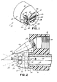
- Fig. 1 is a perspective view of an adjustable powder spray nozzle incorporating the invention of this application.
- Fig. 2 is a side elevational view, partially broken away, of the end of a powder spray gun having the nozzle assembly of Fig. 1 attached thereto.
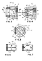
- Fig. 3 is a cross sectional view taken on line 3-3 of Fig. 2.
- Fig. 4 is a cross sectional view taken on line 4-4 of Fig. 3.
- Fig. 5 is a front elevational view of the nozzle assembly of Fig. 1.
- Fig. 6 is an end elevational view of an alternative pair of shafts utilizable in the nozzle of Fig. 1 to change the configuration of powder spray emitted from the nozzle assembly.
- Fig. 7 is a front elevational view of a third pair of shafts utilizable in the nozzle assembly of Fig. 1 to change the configuration of powder spray emitted from the nozzle assembly of Fig. 1.
- With reference to Figs. 1 and 2, it will be seen that the
nozzle assembly 10 of this invention comprises anozzle body 12 adapted to be secured onto the end of a powderspray gun barrel 14. Thebarrel 14 is tubular in configuration- and bas a central powder flow passage 16 through which air entrained powder is transmitted under pressure to and through thenozzle assembly 10. - In the presently preferred embodiment, mounted over the
barrel 14 of the gun inboard from the .nozzle assembly 10, there is anelectrode mount 18. This mount has a rearwardly facing threadedbore 20 formed therein and adapted to receive one end of an electrical connector (not shown) through which electrical power is supplied to anelectrode 22 extending from the front of theelectrode mount 18. Theelectrode 22 is mounted within an electrode holder 26 which is threaded at its rearward end into a threadedbore 28 in theelectrode mount 18. Thebore 28 angularly intersects the threadedbore 20 of the mount. - An electrical contact (not shown) in the rear of the holder 26 is adapted to electrically connect the rearward end of the
electrode 22 to the forward end of an electrical connector (not shown) mounted within thebore 20 of theelectrode mount 18. - The
nozzle body 12 comprises anannular collar 30 and a sleeve. 32 mounted internally of that collar. With reference to Figs. 3 and 4, it will be seen that thecollar 30 has a steppedaxial bore 34 extending therethrough. This bore comprises a large diameterrear end section 36 and a smaller diameterforward end section 38. The small diameter forward end section terminates in an outwardly flaring tapered mouth ordischarge orifice 39. Thelarge diameter section 36 is threaded over at least its rearward portion so as to enable the collar to be threaded over the threaded forward end of the barrel 14(AG 5-1-85) and thereby fixedly secured to the barrel. - Extending transversely through the collar of the
body 12 on opposite sides of thecenter line 40, there are a pair ofbores rotatable shafts bores shaft slot slots shafts slots shafts slots - Machined in one end of each
shaft annular groove 54. These grooves are adapted to receive anassembly pin 56 mounted within a longitudinally extendingbore 58 of thecollar 30. Thepin 56 is a press fit pin located within thebore 58. This pin functions to retain the shafts within thebores shafts bores - At the end of the
shafts radiused groove 54, each shaft has asmall gear stub shaft 64 on the end of each shaft. Atransverse slot 66 extends across the face of eachgear stub shaft 64 upon which the gears are mounted. The gears function to rotate bothshafts slots 66 in the end of the one of theshafts - With reference now to Fig. 4, it will be seen that the
sleeve 32 of thebody 12 has atapered bore 70 formed therein. The upstream end of this bore is annular in configuration and of approximately the same diameter as the bore 16 in thebarrel 14. Thedownstream end 74 of the barrel is . of the same configuration as the powder flow opening 51 defined by theslots shafts sleeve 32 forms a smooth transition flow path from the circular cross section flow path of the barrel 16 to the rectangular or other configured opening 51 defined by the slots in the twoshafts nozzle assembly 10 and through the powder flow opening 51 defined between the twoshafts - With reference now to Fig. 6, there is illustrated a second pair of
shafts 46a, 48a which are identical to theshafts slots 50a, 52a machined therein. In this embodiment, theslots 50a, 52a form a vertical slot opening 51a rather than ahorizontal slot 51 as in the embodiment of Figs. 1-5. In all other respects theshafts 46a, 48a are identical to theshafts - In order to substitute or change from the
shafts nozzle assembly 10 to theshafts 46a, 48a, all that is required is to knock out or remove thepin 56 from thebore 58. With this pin removed, the two shafts may be aially pulled from thebores new shafts 46a, 48a inserted therein. Thepin 56 may then be reinserted into thebore 58 so as to secure theshafts 46a, 48a within thebores sleeve 32 will be rotated 90° so as to align the rectangular outlet end 74 of the tapered bore 70 with the vertically oriented opening 51a defined between the twoshafts 46a, 48a. - With reference to Fig. 7 there is illustrated yet a third pair of shafts 46b, 48b which, except for the
opening 51 b defined therebetween, are identical to theshafts opening 51b therebetween. These shafts could as well be substituted for theshafts sleeve 32 would be substituted for thesleeve 32 of the nozzle body so as to conform thedownstream end 74 of the tapered bore 70 in the sleeve to the elliptical configuration of theopening 51b defined between the two shafts. - The preferred embodiment of the
nozzle assembly 10 has been illustrated and described as being applicable to a spray system for electrostatically spraying powder onto(AG 5-1-85) a target substrate. So long as thenozzle assembly 10 is used for electrostatic spraying applications, thenozzle body 12, as well as theshafts sleeve 32 will all be made from non- metallic, electrically insulative materials so as to minimize the electrical capacitance of the nozzle assembly. The reasons for minimizing such electrical capacitance are well known in the art and are fully described in U.S. Patent No. 3,048,498. On the other hand, the invention is applicable to non- electrostatic powder spray applications, and in that event, the electrode holder 26 andelectrode mount 18 will be omitted and the components of thenozzle assembly 10 may be made of metallic or electrically conductive materials. - In the use of the powder spray gun and nozzle assembly depicted in Figs. 1-5, air entrained powder is supplied under pressure through the bore 16 of the
gun barrel 14 to and through thenozzle assembly 10. This air entrained powder is forced to flow through theopening 51 defined by theslots shafts opening 51 of the nozzle assembly. In the event that the wedge is too wide in configuration at the time it strikes a target substrate, the configuration of that powder spray pattern may be altered by rotating one of theshafts rectangular slot 51. In the case of theelliptical slot 51b, the adjustment changes the minor diameter of that slot so as to vary the pattern of powder emerging from the nozzle. - The primary advantage of the invention of this application is that it enables the powder spray pattern emerging from the nozzle assembly to be easily altered or varied. Prior to this invention, it was not possible with prior art powder spray guns and nozzle assemblies to vary to any appreciable degree from a conically shaped powder spray pattern. The invention of this application enables a powder spray gun to spray any one of a multiplicity of patterns and further enables those patterns to be adjusted in width by simply rotating a shaft of the nozzle assembly.
Claims (8)
Applications Claiming Priority (2)
| Application Number | Priority Date | Filing Date | Title |
|---|---|---|---|
| US732381 | 1985-05-09 | ||
| US06/732,381 US4638951A (en) | 1985-05-09 | 1985-05-09 | Adjustable powder spray nozzle |
Publications (2)
| Publication Number | Publication Date |
|---|---|
| EP0201327A2 true EP0201327A2 (en) | 1986-11-12 |
| EP0201327A3 EP0201327A3 (en) | 1988-04-27 |
Family
ID=24943305
Family Applications (1)
| Application Number | Title | Priority Date | Filing Date |
|---|---|---|---|
| EP86303469A Ceased EP0201327A3 (en) | 1985-05-09 | 1986-05-07 | Improvements in and relating to powder spray guns |
Country Status (5)
| Country | Link |
|---|---|
| US (1) | US4638951A (en) |
| EP (1) | EP0201327A3 (en) |
| JP (1) | JPS61259774A (en) |
| AU (1) | AU570907B2 (en) |
| CA (1) | CA1233632A (en) |
Cited By (1)
| Publication number | Priority date | Publication date | Assignee | Title |
|---|---|---|---|---|
| WO2008017175A1 (en) * | 2006-08-08 | 2008-02-14 | Mettler-Toledo Ag | Metering element on a container for flowable or bulk goods |
Families Citing this family (19)
| Publication number | Priority date | Publication date | Assignee | Title |
|---|---|---|---|---|
| USRE33482E (en) * | 1984-06-21 | 1990-12-11 | Nordson Corporation | Adjustable powder spray gun |
| JPH0673643B2 (en) * | 1986-02-10 | 1994-09-21 | ノードソン株式会社 | Electrostatic coating method and apparatus for powder on non-conductive and void-containing coating object |
| US4830279A (en) * | 1987-09-21 | 1989-05-16 | Nordson Corporation | Flat spray nozzle for a spray gun |
| US5368237A (en) * | 1992-11-23 | 1994-11-29 | Nordson Corporation | Power coating guns with improved spray nozzles and improved method of power coating |
| US5295612A (en) * | 1993-02-25 | 1994-03-22 | Albany International Corp. | Roller nozzle for dispensing fast hardening fluids |
| US5904294A (en) * | 1996-09-13 | 1999-05-18 | Nordson Corporation | Particle spray apparatus and method |
| DE29705444U1 (en) * | 1997-03-26 | 1998-04-23 | OMB Oberdorfer Maschinenfabrik AG, Bütschwil | Adjustable high pressure nozzle |
| US5850976A (en) * | 1997-10-23 | 1998-12-22 | The Eastwood Company | Powder coating application gun and method for using the same |
| AU2003304031A1 (en) * | 2002-10-14 | 2004-10-25 | H. Borger And Co. Gmbh | Method and device for transporting pulverulent material |
| US20040256503A1 (en) * | 2003-05-08 | 2004-12-23 | Young Roy Earl | Shielded electrode |
| US20050126476A1 (en) * | 2003-11-05 | 2005-06-16 | Nordson Corporation | Improved particulate material application system |
| US7793869B2 (en) * | 2003-08-18 | 2010-09-14 | Nordson Corporation | Particulate material applicator and pump |
| US20050115496A1 (en) * | 2003-11-05 | 2005-06-02 | Nordson Corporation | Supply for dry particulate material |
| US20050158187A1 (en) * | 2003-11-24 | 2005-07-21 | Nordson Corporation | Dense phase pump for dry particulate material |
| CA2686395A1 (en) * | 2007-05-09 | 2008-11-20 | Nordson Corporation | Nozzle with internal ramp |
| JP2014117641A (en) * | 2012-12-14 | 2014-06-30 | Seiwa Renewal Works Co Ltd | Nozzle for spraying |
| US9789499B2 (en) | 2015-07-29 | 2017-10-17 | Palo Alto Research Center Incorporated | Filament extension atomizers |
| CN107262320B (en) * | 2017-06-26 | 2023-08-29 | 中信戴卡股份有限公司 | Automatic powder cleaning system for mixed-wire type hub bolt hole and combined powder cleaning gun |
| US12090506B2 (en) | 2020-07-14 | 2024-09-17 | Techtronic Cordless Gp | Powered sprayer |
Family Cites Families (13)
| Publication number | Priority date | Publication date | Assignee | Title |
|---|---|---|---|---|
| US311720A (en) * | 1885-02-03 | Nozzle | ||
| US1161437A (en) * | 1915-03-03 | 1915-11-23 | Willis D Beamer | Carbureter. |
| US1170046A (en) * | 1915-07-12 | 1916-02-01 | Guy Carleton | Valve for fluid-conduits. |
| US1437423A (en) * | 1921-07-05 | 1922-12-05 | Henry A May | Governing valve for internal-combustion motors |
| US2366264A (en) * | 1943-06-04 | 1945-01-02 | Mack Mfg Corp | Nozzle |
| US2587704A (en) * | 1947-11-29 | 1952-03-04 | Standard Oil Co | Tangential cylinder valve |
| US3435804A (en) * | 1967-04-10 | 1969-04-01 | Anthony J Orlowski | Automatic fish feeder |
| US4169560A (en) * | 1975-03-29 | 1979-10-02 | Elektrostatische Spritz-- und Beflockungsgesellschaft G.F. Vohringer GmbH | Electrostatic spray gun for powdered material |
| CH620600A5 (en) * | 1977-05-12 | 1980-12-15 | Alex Hengartner | |
| DE2736314C3 (en) * | 1977-08-12 | 1980-07-31 | Alfred Kaercher Gmbh & Co, 7057 Winnenden | Nozzle for spraying a pressurized medium |
| DE2906648C3 (en) * | 1979-02-21 | 1981-09-10 | Alfred Kärcher GmbH & Co, 7057 Winnenden | Spray nozzle arrangement for high pressure cleaning devices |
| US4380320A (en) * | 1981-02-25 | 1983-04-19 | Nordson Corporation | Electrostatic powder spray gun nozzle |
| DE3230247A1 (en) * | 1982-08-13 | 1984-02-16 | J. Wagner Gmbh, 7990 Friedrichshafen | Adjustable nozzle arrangement |
-
1985
- 1985-05-09 US US06/732,381 patent/US4638951A/en not_active Expired - Fee Related
-
1986
- 1986-04-22 CA CA000507281A patent/CA1233632A/en not_active Expired
- 1986-05-07 AU AU57212/86A patent/AU570907B2/en not_active Ceased
- 1986-05-07 EP EP86303469A patent/EP0201327A3/en not_active Ceased
- 1986-05-09 JP JP61105006A patent/JPS61259774A/en active Pending
Cited By (2)
| Publication number | Priority date | Publication date | Assignee | Title |
|---|---|---|---|---|
| WO2008017175A1 (en) * | 2006-08-08 | 2008-02-14 | Mettler-Toledo Ag | Metering element on a container for flowable or bulk goods |
| CN101500895B (en) * | 2006-08-08 | 2011-01-05 | 梅特勒-托利多公开股份有限公司 | Ingredient dispensing elements on containers for free-flowing or pourable bulk materials |
Also Published As
| Publication number | Publication date |
|---|---|
| EP0201327A3 (en) | 1988-04-27 |
| JPS61259774A (en) | 1986-11-18 |
| AU5721286A (en) | 1986-11-13 |
| CA1233632A (en) | 1988-03-08 |
| US4638951A (en) | 1987-01-27 |
| AU570907B2 (en) | 1988-03-24 |
Similar Documents
| Publication | Publication Date | Title |
|---|---|---|
| US4638951A (en) | Adjustable powder spray nozzle | |
| EP0382768B1 (en) | Flat spray nozzle for a spray gun | |
| US5685482A (en) | Induction spray charging apparatus | |
| US4221339A (en) | Liquid spraying device | |
| EP0089817B1 (en) | Air atomising nozzle assembly | |
| EP0059045B1 (en) | Electrostatic powder spray gun nozzle | |
| DE69002640T2 (en) | Electrostatic spray coating device with rotary atomizer. | |
| US5368237A (en) | Power coating guns with improved spray nozzles and improved method of power coating | |
| CA1071855A (en) | Projecting nozzle for powder coating capable of adjusting the projection pattern of powder paint | |
| CA1125002A (en) | Adapting means providing detachable mounting of an induction-charging adapter head on a spray device | |
| DE69728030T2 (en) | Interchangeable lining for the bell body of a rotary atomizer | |
| EP0808663A2 (en) | Electrostatic spraying apparatus | |
| US4634058A (en) | Powder spray gun | |
| EP0123964B1 (en) | Process and device for the electrostatic spraying of powder particles onto a surface | |
| JP6473629B2 (en) | Electrostatic spraying equipment | |
| US3590318A (en) | Powder coating apparatus producing a flat powder spray | |
| EP0044676B1 (en) | Low capacitance airless spray apparatus | |
| US6676049B2 (en) | Bell cup powder spray applicator | |
| JP3842324B2 (en) | Coating material spraying equipment | |
| EP0227368A2 (en) | Adjustable flat pattern powder spray gun | |
| US3342418A (en) | Coating apparatus | |
| US7055768B1 (en) | Rotary device for transmission of material in particulate form | |
| KR800001711Y1 (en) | Spray nozzle for powder coating with adjustable spray pattern | |
| EP0154416B1 (en) | Powder spray gun | |
| EP1354633A1 (en) | Spraying device comprising a hollow electrode |
Legal Events
| Date | Code | Title | Description |
|---|---|---|---|
| PUAI | Public reference made under article 153(3) epc to a published international application that has entered the european phase |
Free format text: ORIGINAL CODE: 0009012 |
|
| AK | Designated contracting states |
Kind code of ref document: A2 Designated state(s): BE CH DE FR GB IT LI LU NL |
|
| PUAB | Information related to the publication of an a document modified or deleted |
Free format text: ORIGINAL CODE: 0009199EPPU |
|
| RA1 | Application published (corrected) |
Date of ref document: 19861217 Kind code of ref document: A2 |
|
| PUAL | Search report despatched |
Free format text: ORIGINAL CODE: 0009013 |
|
| RHK1 | Main classification (correction) |
Ipc: B05B 5/02 |
|
| AK | Designated contracting states |
Kind code of ref document: A3 Designated state(s): BE CH DE FR GB IT LI LU NL |
|
| 17P | Request for examination filed |
Effective date: 19881012 |
|
| 17Q | First examination report despatched |
Effective date: 19891003 |
|
| STAA | Information on the status of an ep patent application or granted ep patent |
Free format text: STATUS: THE APPLICATION HAS BEEN REFUSED |
|
| 18R | Application refused |
Effective date: 19901217 |
|
| RIN1 | Information on inventor provided before grant (corrected) |
Inventor name: GABRIEL, ALXANDER |