EP0201363B1 - Rauhwalze für Rauhmaschinen - Google Patents
Rauhwalze für Rauhmaschinen Download PDFInfo
- Publication number
- EP0201363B1 EP0201363B1 EP19860400494 EP86400494A EP0201363B1 EP 0201363 B1 EP0201363 B1 EP 0201363B1 EP 19860400494 EP19860400494 EP 19860400494 EP 86400494 A EP86400494 A EP 86400494A EP 0201363 B1 EP0201363 B1 EP 0201363B1
- Authority
- EP
- European Patent Office
- Prior art keywords
- mini
- raising
- workers
- raising roller
- fittings
- Prior art date
- Legal status (The legal status is an assumption and is not a legal conclusion. Google has not performed a legal analysis and makes no representation as to the accuracy of the status listed.)
- Expired - Lifetime
Links
- 239000004744 fabric Substances 0.000 claims description 10
- 230000005540 biological transmission Effects 0.000 claims description 6
- 229920000742 Cotton Polymers 0.000 claims description 4
- 229920001971 elastomer Polymers 0.000 claims description 4
- 239000004745 nonwoven fabric Substances 0.000 claims description 3
- 239000002759 woven fabric Substances 0.000 claims 2
- 238000007790 scraping Methods 0.000 description 10
- 210000004209 hair Anatomy 0.000 description 6
- 239000013256 coordination polymer Substances 0.000 description 5
- 230000008878 coupling Effects 0.000 description 4
- 238000010168 coupling process Methods 0.000 description 4
- 238000005859 coupling reaction Methods 0.000 description 4
- 238000004519 manufacturing process Methods 0.000 description 4
- 230000009471 action Effects 0.000 description 3
- 230000008901 benefit Effects 0.000 description 3
- 238000000034 method Methods 0.000 description 3
- 238000011282 treatment Methods 0.000 description 3
- 241000287107 Passer Species 0.000 description 2
- 238000005452 bending Methods 0.000 description 2
- 230000008859 change Effects 0.000 description 2
- 238000004140 cleaning Methods 0.000 description 2
- 239000013013 elastic material Substances 0.000 description 2
- 238000009434 installation Methods 0.000 description 2
- 238000012423 maintenance Methods 0.000 description 2
- 210000000056 organ Anatomy 0.000 description 2
- 238000012856 packing Methods 0.000 description 2
- 230000008569 process Effects 0.000 description 2
- 229910001018 Cast iron Inorganic materials 0.000 description 1
- RRHGJUQNOFWUDK-UHFFFAOYSA-N Isoprene Chemical compound CC(=C)C=C RRHGJUQNOFWUDK-UHFFFAOYSA-N 0.000 description 1
- 230000003416 augmentation Effects 0.000 description 1
- 239000003638 chemical reducing agent Substances 0.000 description 1
- 238000010276 construction Methods 0.000 description 1
- 238000006073 displacement reaction Methods 0.000 description 1
- 238000009826 distribution Methods 0.000 description 1
- 230000000694 effects Effects 0.000 description 1
- 229940082150 encore Drugs 0.000 description 1
- 239000000945 filler Substances 0.000 description 1
- 239000000463 material Substances 0.000 description 1
- 229920001195 polyisoprene Polymers 0.000 description 1
- 230000001869 rapid Effects 0.000 description 1
- 230000000284 resting effect Effects 0.000 description 1
- 230000000717 retained effect Effects 0.000 description 1
- 238000006748 scratching Methods 0.000 description 1
- 230000002393 scratching effect Effects 0.000 description 1
- 210000001519 tissue Anatomy 0.000 description 1
Images


Classifications
-
- D—TEXTILES; PAPER
- D06—TREATMENT OF TEXTILES OR THE LIKE; LAUNDERING; FLEXIBLE MATERIALS NOT OTHERWISE PROVIDED FOR
- D06C—FINISHING, DRESSING, TENTERING OR STRETCHING TEXTILE FABRICS
- D06C11/00—Teasing, napping or otherwise roughening or raising pile of textile fabrics
Definitions
- the invention relates to machines for scraping fabrics, woven, non-woven, or mesh, in finishing machines such as, in particular, woolen machines.
- the machines of this kind currently known and used are illustrated by document DE-A-3,307,881; they comprise at least one worker essentially constituted by a central core mounted on fixed bearings and driven in rotation and by rotating cylindrical elements of smaller diameter, or working cylinders, regularly distributed around the periphery of the central core and carrying scraping linings which can be of the same type (hair or counterweight) for the same worker.
- the central core is driven in rotation by motor means, and all the cylindrical elements are driven in the same direction of rotation and at the same speed.
- the object of the invention is to provide a worker, as well as a scraping machine equipped with at least one such worker, of a new type making it possible to implement another method of scraping facilitating the obtaining of various scraping.
- Another object of the invention is to provide a worker and a machine of this kind which allow greater efficiency of the treatment, which can be carried out by a single passage of the article.
- Another object of the invention is to reduce the axial size, the complexity and the manufacturing and maintenance cost of the worker and the machine.
- Another object of the invention is to allow easier and more effective cleaning of the scraping linings.
- each cylindrical element itself is made up of subelements of reduced length. , called mini-workers.
- the invention also relates to a machine, of the woolly type, for scraping articles such as fabrics, knits and nonwovens, characterized in that it comprises at least one worker according to the invention as defined above.
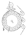
- each pile or counterweight worker is composed of a cylinder 1, turning on itself around its axis 2, and supporting a certain number of "Mini- T "3 which, depending on their direction of filling, will define the" pile "or” counterweight "type (Figs. 2 and 3).
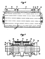
- Mini-T lines 11 and 12 mounted on bearings 13 are driven by belts, sprockets or chains by the element 10 at the end of the line which is, in fact, the pulley, the sprocket receiving the drive command.
- Fig. 1 shows, by way of example, a drive by fixed belts: one between 6 and 7 making the complete turn of the worker; the other between 8 and 9 also going around the worker so that all the lines of "Mini-T" are always driven by at least one of the two.
- Fig. 5 shows a counterweight worker with mini counterweight workers (Mini-T-CP), shows another way of driving the Mini-T by means of a command not concentric with the central cylinder ⁇ but coming from the outside (as is made in the majority of classic woolen fabrics).
- Fig. 6 represents a fur worker with Mini-TP; in this case we put only one belt 21 for driving the Mini-T to ensure their speed variation and we add a circular connecting belt (or chain) 28 around all the Mini-T to make them even in the area where the main belt leaves the worker to receive his variation command.
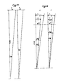
- FIG. 7 Regarding the training of mini workers by variable pulley (Fig. 7) if we take again Fig. 1 where a worker is shown whose Mini-T 3 are driven by belts attached to a crown 4 at variable speed, one can imagine another drive arrangement:
- variable pulley is made up as follows: a fixed central part 71 with double belt slope, keyed onto the shaft to be driven; two laterally movable parts 72, each keyed to the above fixed part and retained in their lateral displacement by springs 73 resting on rings 74 fixed on the central axis 75 of the mini-worker.
- the inside of the opening 13 'of the cast iron bearing 13 is equipped with a bearing 32 internally lined with an elastic material 31, the central opening 31 'of which is of a shape allowing the drive of a part which is housed therein with the same shape.
- This ring 33 is pierced on its axis and also has an inner lining 35 made of elastic material and capable of receiving, in its opening 36, the part 37 of the mini worker 11 who can therefore drive the ring 33 and therefore the inner elastic ring 31 of the bearing mounted on the bearing 32.
- the part 38 of the mini-worker 11 makes it possible to slide the ring 33 after removing and sliding the stop ring (elastic ring) of which 41 designates the housing.
- the junction ring 33 can then come out of its housing in the bearing and thus release the mini-worker 11 and ring 33 assembly.
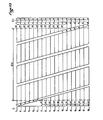
- Fig, 13 shows a solution for distributing mini workers on the central core of a fur worker, for example.
- mini-workers of a certain reduced length have been chosen, the main criterion being to resist bending, taking into account the speed of the central core.
- the mini-workers MT are arranged in a spiral diagonal which ensures that each hollow represented by a bearing corresponds to the same number of fillers represented by the Mini-T of the other lines.
- the mini-workers are designated by MT particularly on each side because in certain places the MINI-T are useless since outside the useful zone ZU; (the control area is designated by ZC). They were then replaced by axes A of connection to transmit the command.
- the control area on the right represents the line of pulleys or sprockets for mini workers.
- Each pulley (or each pinion) is located between two quick coupling bearings.
- each fur or counterweight worker is completely independent of the following (s) and therefore there is no influence of one on the other (Fig. 13 explains this phenomenon).
- the actual angle of attack therefore varies since the width of the conventional linings is standard (i.e. 19 mm ⁇ 5% for the felt / cotton-based linings and 23 mm ⁇ 5% for the cotton / linen / rubber-based linings).
- the production of the new system can be estimated to be significantly higher, at an equal price, than conventional machines.
- the lines 1 of bearings of the axes of the mini-workers can each be implanted on a lateral facet of the nucleus thus shaped.
Landscapes
- Engineering & Computer Science (AREA)
- Textile Engineering (AREA)
- Treatment Of Fiber Materials (AREA)
- Preliminary Treatment Of Fibers (AREA)
- Rolls And Other Rotary Bodies (AREA)
Claims (13)
Applications Claiming Priority (2)
| Application Number | Priority Date | Filing Date | Title |
|---|---|---|---|
| FR8503741 | 1985-03-14 | ||
| FR8503741A FR2578861B1 (fr) | 1985-03-14 | 1985-03-14 | Travailleur pour machine a gratter les tissus, tricots et non tisses dans les machines telles, notamment, que les laineuses et machines comportant l'utilisation de cylindres gratteurs ou ebouriffeurs. |
Publications (2)
| Publication Number | Publication Date |
|---|---|
| EP0201363A1 EP0201363A1 (de) | 1986-11-12 |
| EP0201363B1 true EP0201363B1 (de) | 1990-10-03 |
Family
ID=9317175
Family Applications (1)
| Application Number | Title | Priority Date | Filing Date |
|---|---|---|---|
| EP19860400494 Expired - Lifetime EP0201363B1 (de) | 1985-03-14 | 1986-03-10 | Rauhwalze für Rauhmaschinen |
Country Status (7)
| Country | Link |
|---|---|
| EP (1) | EP0201363B1 (de) |
| JP (1) | JPS61215764A (de) |
| DD (1) | DD245683A5 (de) |
| DE (1) | DE3674631D1 (de) |
| ES (1) | ES8702538A1 (de) |
| FR (1) | FR2578861B1 (de) |
| PT (1) | PT82206B (de) |
Families Citing this family (2)
| Publication number | Priority date | Publication date | Assignee | Title |
|---|---|---|---|---|
| FR2609063A1 (fr) * | 1986-12-24 | 1988-07-01 | Mach Textiles | Laineuse |
| US4897901A (en) * | 1987-12-21 | 1990-02-06 | Michel Scholaert | Machine for brushing fabrics, equipped with counter-pile workers and with teazles |
Family Cites Families (8)
| Publication number | Priority date | Publication date | Assignee | Title |
|---|---|---|---|---|
| FR1371147A (fr) * | 1963-10-15 | 1964-08-28 | Mueller Franz Maschf | Machine à lainer à tambour |
| DE1760830A1 (de) * | 1968-07-06 | 1972-01-05 | Mueller Franz | Tambour-Rauhmaschine |
| DE2045673A1 (en) * | 1970-09-16 | 1972-03-23 | Girmes - Werke AG, 4156 Oedt | Napping control - to synchronise peripheral speeds of skeleton cylinder and carding rollers |
| FR2169977B3 (de) * | 1972-02-04 | 1976-01-30 | Bolli Giuseppe It | |
| JPS5442490A (en) * | 1977-09-03 | 1979-04-04 | Terada Shiyouzou | Raising machine using supersonic |
| JPS5558696U (de) * | 1978-10-13 | 1980-04-21 | ||
| JPS5713357U (de) * | 1980-06-30 | 1982-01-23 | ||
| DE3307881A1 (de) * | 1983-03-05 | 1984-09-06 | Leo Sistig Kg, 4150 Krefeld | Antrieb fuer die rauhwalzen einer tambour-rauhmaschine |
-
1985
- 1985-03-14 FR FR8503741A patent/FR2578861B1/fr not_active Expired
-
1986
- 1986-03-10 DE DE8686400494T patent/DE3674631D1/de not_active Expired - Lifetime
- 1986-03-10 EP EP19860400494 patent/EP0201363B1/de not_active Expired - Lifetime
- 1986-03-13 JP JP5386286A patent/JPS61215764A/ja active Granted
- 1986-03-14 ES ES553000A patent/ES8702538A1/es not_active Expired
- 1986-03-14 PT PT8220686A patent/PT82206B/pt not_active IP Right Cessation
- 1986-03-14 DD DD28790386A patent/DD245683A5/de not_active IP Right Cessation
Also Published As
| Publication number | Publication date |
|---|---|
| ES553000A0 (es) | 1987-01-16 |
| ES8702538A1 (es) | 1987-01-16 |
| FR2578861B1 (fr) | 1987-05-29 |
| DE3674631D1 (de) | 1990-11-08 |
| FR2578861A1 (fr) | 1986-09-19 |
| JPS6327467B2 (de) | 1988-06-03 |
| PT82206A (fr) | 1986-04-01 |
| JPS61215764A (ja) | 1986-09-25 |
| DD245683A5 (de) | 1987-05-13 |
| EP0201363A1 (de) | 1986-11-12 |
| PT82206B (pt) | 1992-05-29 |
Similar Documents
| Publication | Publication Date | Title |
|---|---|---|
| FR2818295A1 (fr) | Dispositif de tirage en continu pour machine a tricoter | |
| EP0201363B1 (de) | Rauhwalze für Rauhmaschinen | |
| CA1118588A (fr) | Dispositif de coupe et d'ouverture | |
| CH615230A5 (en) | Drive assembly for spinning machine | |
| FR2600345A1 (fr) | Machine de traitement de tiges vegetales de matieres fibreuses | |
| CH632397A5 (fr) | Procede et appareil de fabrication d'elements de filtre en forme de tige pour la fumee de tabac. | |
| FR2828895A1 (fr) | Dispositif pour aiguilleter un voile de fibres pouvant etre transporte | |
| EP1383948B1 (de) | Verfahren zum kämmen und geradlinige kämmmaschine dafür | |
| FR2503686A1 (fr) | Dispositif pour realiser, enlever et deposer en continu des boucles de fil | |
| BE1011429A3 (fr) | Metier a tricoter circulaire. | |
| FR2460607A1 (fr) | Ensemble de traitement pour machines de battage | |
| WO2002088440A2 (fr) | Procède de peignage rectiligne et peigneuse rectiligne pour la mise en oeuvre de ce procède | |
| WO1998037264A1 (fr) | Procedes et dispositifs pour realiser une nappe et un produit textile continu profiles | |
| CH619743A5 (en) | Machine for blending, defelting, shortening or sizing natural or artificial fibres | |
| EP0208628B1 (de) | Einrichtung zur Regelung der Spannung eines Fadens bei verschiedenen die Fadeneigenschaften ändernden Produktionsstufen während seiner Herstellung | |
| FR2788936A1 (fr) | Faconneuse semi-verticale | |
| FR2484293A1 (fr) | Machine a trier des produits d'une forme allongee, conique, ovoide ou prismatique et notamment des carottes | |
| FR2607526A1 (fr) | Brosse de nettoyage pour machine de grattage a tambour, et machine de grattage a tambour equipee d'une telle brosse | |
| FR2515696A1 (fr) | Dispositif de condensation du voile de fibres prelevees sur une carde ou analogue | |
| FR2551772A1 (fr) | Tete de peignage a entrainement par chaine pour rubans de fibres textiles, particulierement pour des bancs d'etirage | |
| EP0299131A1 (de) | Verfahren zur Herstellung eines Flammengarnes und Vorrichtung für das Ausführen des Verfahrens | |
| FR2584103A1 (fr) | Dispositif de defibrage de vegetaux fibreux | |
| FR2565069A1 (fr) | Dispositif pour etirer positivement des patons pour la fabrication industrielle de pains longs | |
| FR2794138A1 (fr) | Dispositif d'etirage de meches formees de fibres textiles | |
| FR2650309A1 (fr) | Machine de filature permettant de realiser des files de fibres presentant des effets de fantaisie sur leur longueur et nouveaux types de files ainsi obtenus |
Legal Events
| Date | Code | Title | Description |
|---|---|---|---|
| PUAI | Public reference made under article 153(3) epc to a published international application that has entered the european phase |
Free format text: ORIGINAL CODE: 0009012 |
|
| 17P | Request for examination filed |
Effective date: 19860312 |
|
| AK | Designated contracting states |
Kind code of ref document: A1 Designated state(s): BE CH DE FR GB IT LI NL |
|
| 17Q | First examination report despatched |
Effective date: 19880826 |
|
| GRAA | (expected) grant |
Free format text: ORIGINAL CODE: 0009210 |
|
| AK | Designated contracting states |
Kind code of ref document: B1 Designated state(s): BE CH DE FR GB IT LI NL |
|
| PG25 | Lapsed in a contracting state [announced via postgrant information from national office to epo] |
Ref country code: IT Free format text: LAPSE BECAUSE OF FAILURE TO SUBMIT A TRANSLATION OF THE DESCRIPTION OR TO PAY THE FEE WITHIN THE PRESCRIBED TIME-LIMIT;WARNING: LAPSES OF ITALIAN PATENTS WITH EFFECTIVE DATE BEFORE 2007 MAY HAVE OCCURRED AT ANY TIME BEFORE 2007. THE CORRECT EFFECTIVE DATE MAY BE DIFFERENT FROM THE ONE RECORDED. Effective date: 19901003 Ref country code: NL Effective date: 19901003 Ref country code: GB Effective date: 19901003 |
|
| REF | Corresponds to: |
Ref document number: 3674631 Country of ref document: DE Date of ref document: 19901108 |
|
| NLV1 | Nl: lapsed or annulled due to failure to fulfill the requirements of art. 29p and 29m of the patents act | ||
| PG25 | Lapsed in a contracting state [announced via postgrant information from national office to epo] |
Ref country code: LI Effective date: 19910331 Ref country code: CH Effective date: 19910331 Ref country code: BE Effective date: 19910331 |
|
| GBV | Gb: ep patent (uk) treated as always having been void in accordance with gb section 77(7)/1977 [no translation filed] | ||
| PLBE | No opposition filed within time limit |
Free format text: ORIGINAL CODE: 0009261 |
|
| STAA | Information on the status of an ep patent application or granted ep patent |
Free format text: STATUS: NO OPPOSITION FILED WITHIN TIME LIMIT |
|
| 26N | No opposition filed | ||
| BERE | Be: lapsed |
Owner name: SCHOLAERT MICHEL Effective date: 19910331 |
|
| PG25 | Lapsed in a contracting state [announced via postgrant information from national office to epo] |
Ref country code: FR Effective date: 19911129 |
|
| REG | Reference to a national code |
Ref country code: CH Ref legal event code: PL |
|
| PG25 | Lapsed in a contracting state [announced via postgrant information from national office to epo] |
Ref country code: DE Effective date: 19920101 |
|
| REG | Reference to a national code |
Ref country code: FR Ref legal event code: ST |