EP0203912A1 - Rohrpoststation und/oder -weiche - Google Patents
Rohrpoststation und/oder -weiche Download PDFInfo
- Publication number
- EP0203912A1 EP0203912A1 EP86890157A EP86890157A EP0203912A1 EP 0203912 A1 EP0203912 A1 EP 0203912A1 EP 86890157 A EP86890157 A EP 86890157A EP 86890157 A EP86890157 A EP 86890157A EP 0203912 A1 EP0203912 A1 EP 0203912A1
- Authority
- EP
- European Patent Office
- Prior art keywords
- glasses
- tube
- housing
- pipe
- pipe section
- Prior art date
- Legal status (The legal status is an assumption and is not a legal conclusion. Google has not performed a legal analysis and makes no representation as to the accuracy of the status listed.)
- Granted
Links
- 239000011521 glass Substances 0.000 claims description 38
- 238000007789 sealing Methods 0.000 claims description 4
- 230000005540 biological transmission Effects 0.000 description 2
- 230000002349 favourable effect Effects 0.000 description 2
- 238000010276 construction Methods 0.000 description 1
- 238000000034 method Methods 0.000 description 1
Images

Classifications
-
- B—PERFORMING OPERATIONS; TRANSPORTING
- B65—CONVEYING; PACKING; STORING; HANDLING THIN OR FILAMENTARY MATERIAL
- B65G—TRANSPORT OR STORAGE DEVICES, e.g. CONVEYORS FOR LOADING OR TIPPING, SHOP CONVEYOR SYSTEMS OR PNEUMATIC TUBE CONVEYORS
- B65G51/00—Conveying articles through pipes or tubes by fluid flow or pressure; Conveying articles over a flat surface, e.g. the base of a trough, by jets located in the surface
- B65G51/04—Conveying the articles in carriers having a cross-section approximating that of the pipe or tube; Tube mail systems
- B65G51/26—Stations
- B65G51/32—Stations for despatch, delivery, and transit
Definitions
- the invention relates to a pneumatic tube station and / or switch with a tube piece arranged in a housing, which is movably connected at one end to a (first) connecting tube provided on one side of the housing and to one or more on the other side of the housing provided further connecting pipes can be optionally connected using a drive.
- one end of the pipe section is tightly connected to a first connecting pipe and can be pivoted about an axis near this end between two positions, in which the other end of the pipe section, each with one of two further connecting pipes is sealingly connected.
- the known station can also be used as a transmitting and receiving station due to the arrangement of a sleeve memory in the housing, there are various problems, in particular in the deflection and sealing of the pipe section.
- the station is not suitable for a large number of connecting pipes, because in this case there are unsustainable angles between the pipe section and the connecting pipes and the dimensions would be too extensive.
- the axis of rotation of the glasses is aligned with the axis of the (first) connecting tube.
- the drive may be advisable for the drive to act on the end of the pipe section that is rotatably connected to the (first) connecting pipe.
- a design which is favorable for controlling the pneumatic tube station provides for switching cams for a microswitch or the like to be provided on the glasses.
- the station is also to be used as a transmitting and / or receiving station, it is particularly advisable to provide a bypass tube which is pneumatically connected to the tube piece on the one hand and on the other hand held in a wide eye of the glasses and together with the tube piece and the glasses is rotatable.
- At least one opening of the base plate is assigned a closure piece which can be moved vertically by means of a lifting and lowering device.
- An advantageous embodiment of the invention with regard to the guidance of the sleeves is characterized in that the tube piece is curved in an S-shape.
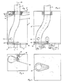
- FIG. 1 shows a first embodiment of a station according to the invention in a schematic side view, partly in section
- FIG. 2 shows a top view of the base plate in the direction of the arrow 11 in FIGS. 1, 3 and 4 in relation to FIGS. 1 and 2 analog representations a pneumatic tube station according to the invention (second embodiment) with a total of seven connecting pipes
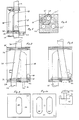
- Fig. 5 and 6 in analog representations a third embodiment of a pneumatic tube station according to the invention
- Fig. 7 and 8 a fourth embodiment of the invention in a partially sectioned schematic side view in two operating positions
- FIG. 9 the schematic view of an upper rotary element of this embodiment
- FIG. 10 the schematic view double-eyed glasses of this embodiment
- FIGS. 11 to 13 in a highly simplified representation three further exemplary embodiments of the invention.
- a first embodiment of the invention has a single, first connecting pipe 2 on one side of a housing 1, whereas three connecting pipes 3, 4, 5 lead to the opposite side of the housing.
- the connecting pipe 2 ends in the housing 1 in a ring 6, in which one end of a pipe section 8 is rotatably mounted by means of a collar 7.
- a sealing ring 9 can be provided between the collar 7 and the ring 6.
- the pipe section 8 is provided with a pulley 10, so that the pipe section 8 can be rotated with respect to the connecting pipe 2 via the pulley 11 of a motor 12 and a toothed or V-belt 13.
- a base plate 14 is arranged, in which the other three connecting pipes 3, 4, 5 open.
- glasses 15 can be rotated about an axis 16 which runs parallel to the axis 17 of the first connecting pipe 2 or is flush therewith.
- the other end of the S-shaped pipe section 8 is held in these glasses 15. It can be seen that when the pipe section 8 is rotated by means of the motor 12, the end of the pipe section 8 held in the glasses, together with the glasses 15, can also be rotated. Upon rotation through 90 ° or 180 °, the end of the pipe section 8 thus comes out of its position aligned with the end of the connecting pipe 3 in positions in which it is aligned with the ends of the connecting pipes 4 and 5. If necessary, the glasses 8 can have a seal, not shown here.
- a microswitch 18 is provided on the one hand to report back the respective position of the glasses 15 and can be actuated by cams 19 protruding from the glasses.
- the pipe section 8 has, in a known manner, a pipe switch 20 which is actuated when driving through a bushing.
- the station shown can be used as a triple switch. But it is also possible, e.g. to use the connecting pipe 3 as a flow pipe and the connecting pipes 4, 5 as a transmission or. Train receiving storage for incoming and outgoing pneumatic tube boxes.
- the pneumatic post station according to FIGS. 3 and 4 is essentially the same as the one described above and the same reference numerals are used for the same parts.
- a single connecting pipe 2 is provided on one side of the station, but six connecting pipes 21a-21f are arranged on the other side.
- a geared motor 12 drives the glasses 16 directly here, a feedback (not shown) being provided for the respective angular position of the glasses.
- the station shown can be used as a pure switch or as a switch with send / receive functions. This example shows the compact structure of the station that can be achieved by the invention.
- the station shown in FIGS. 5 and 6 is particularly suitable as a transmitting / receiving station, with pneumatic braking of incoming bushings on an air cushion being possible.
- the housing 1 has a (first) connecting pipe 2 at its upper end in the drawing.
- a base plate 14 at the other end of the housing 1 three connecting tubes 22, 23, 24 are provided, e.g. the tube 22 serves as a continuous tube, the tube 23 as a receiving tube and the tube 24 as a transmitter tube.
- glasses 25 with two eyes 26, 27 are provided, the tube piece 8 opening into an eye 26.
- the other eye 27 opens one end of a bypass tube 28 which is pneumatically connected to the pipe section 8 via an opening 29.
- the connecting pipes 22, 23, 24 open into three openings 22 ', 23', 24 'of the base plate 14.
- seals, drives, pipe switches, etc. which are not shown, are also present in this embodiment.
- the pipe section 8 lies above the opening 22 'of the flow pipe 22, so that the bushings can run through in both directions.
- the glasses 25 are rotated clockwise by 60 °, the end of the pipe section 8 lies sealingly against the base plate 14.
- the moving transport air is passed through the bypass tube 28.
- a sleeve arrives in this position from the connecting pipe 2, it is braked in the pipe section 8 on an air cushion above the base plate 14.
- the tube switch 20 indicates the end position of the sleeve on the base plate, the glasses are rotated clockwise by 60 ° so that the sleeve can now fall out of the receiving tube 23 (position according to FIG. 6). If the glasses 25 are rotated further from this position by 120 ° (transmitting position), the tube piece 8 is above the transmitting tube 24 and a bushing stored here can be suctioned off.
- the pneumatic post station shown in FIGS. 7 to 10 has two special features, namely on the one hand a flat cross section of all tubes, which means that even bulky, non-rolled goods, such as e.g. File folder, is possible and on the other hand a lifting and lowering device for the pneumatic tube rifles.
- a first connecting pipe 30 with a flat cross section opens into an upper cover plate 31.
- a rotary element 32 is rotatably mounted (FIG. 9).
- circular glasses 34 with two eyes 35, 36 are rotatably mounted on a base plate 33.
- An opening 37 of the upper rotary element 32 corresponding to the tube cross section is connected to an eye 35 of the glasses 34 via a tube piece 38.
- a bypass pipe 39 is provided, which is connected to the other eye 36 of the glasses 34 and is pneumatically connected to the pipe section 38.
- the glasses 34 can be rotated by means of a motor 40, e.g. a pinion 41 engages on the circumference of the circular glasses 34.
- An opening 42 in the base plate 33 can be closed by means of a closure piece 43 which can be moved up and down with the aid of a rod 44 and a lifting and lowering device 45.
- a lower connecting pipe 46 is connected to a further opening of the base plate 33.
- the station shown works as follows. In the position shown in FIG. 7, the pneumatic tube bushings can pass through the station in both directions through the connecting tubes 30 and 46 via the tube piece 38. The end of the bypass tube 39 is closed by the closure piece 43. In the position according to FIG. 8, however, bushes coming from the connecting pipe 30 can enter the pipe section 38, which is initially closed by the closure piece 43. The conveying air passes through the bypass pipe 39 unhindered into the lower connecting pipe 46. The sleeve is braked on the air cushion until a travel contact 20 indicates the end position of the sleeve. Now the lifting and lowering device 45 lowers the closure piece 43 and the sleeve can be removed.
- FIGS. 11 and 12 show a simple transceiver station with a rotatable tube section 47 and one-eyed glasses 48.
- the receptacle can be received without being braked or - also braked by means of a braking position of the glasses 48.
- FIGS. 13 and 14 show an embodiment which corresponds in principle to the embodiment according to FIGS. 7 to 10, but the pipe cross section is circular.
- a tube piece 49, a bypass tube 50 and two-eyed glasses 51 are provided.
- FIGS. 15 and 16 shows a station with one-eyed glasses 52 and a pipe section 53, e.g. one pass, one receive and two transmit positions are possible.
- the pipe section is expediently curved in an S-shape, but it can, e.g. 7 and 8 show, also run in a straight line.
- the S-shaped version results in lower driving noise.
Landscapes
- Physics & Mathematics (AREA)
- Engineering & Computer Science (AREA)
- Fluid Mechanics (AREA)
- Mechanical Engineering (AREA)
- Invalid Beds And Related Equipment (AREA)
Abstract
Description
- Die Erfindung bezieht sich auf eine Rohrpoststation und/oder -weiche mit einem in einem Gehäuse angeordneten Rohrstück, das mit einem Ende mit einem an einer Seite des Gehäuses vorgesehenen (ersten) Anschlußrohr beweglich verbunden und mit einem oder mehreren, an der anderen Seite des Gehäuses vorgesehenen weiteren Anschlußrohren mit Hilfe eines Antriebes wahlweise verbindbar ist.
- Bei einer derartigen, aus der AT-PS 328.361 bekannt gewordenen Station ist ein Ende des Rohrstückes mit einem ersten Anschlußrohr dicht verbunden und um eine in Nähe dieses Endes liegende Achse zwischen zwei Stellungen verschwenkbar, in welchen das andere Ende des Rohrstückes mit je einem von zwei weiteren Anschlußrohren dichtend verbunden ist.
- Wiewohl die bekannte Station durch die Anordnung eines Hülsenspeichers in dem Gehäuse auch als Sende-und Empfangsstation verwendbar ist, ergeben sich doch verschiedene Probleme, insbesondere bei der Umlenkung und Abdichtung des Rohrstückes. Die Station ist für eine größere Anzahl von Anschlußrohren nicht geeignet, da sich in diesem Fall untragbare Winkel zwischen dem Rohrstück und den Anschlußrohren ergeben und die Abmessungen zu ausladend würden.
- Es ist ein Ziel der Erfindung, eine Rohrpoststation und/oder -weiche zu schaffen, die auch bei einer größeren Anzahl von Anschlußrohren einen kompakten Aufbau aufweist und die in allen Betriebsstellungen möglichst gleichbleibende Umlenkwinkel für die Hülsen aufweist.
- Dieses Ziel läßt sich mit einer Station der eingangs genannten Art erreichen, bei welcher erfindungsgemäß das Rohrstück mit dem (ersten) Anschlußrohr drehbar verbunden ist und das andere Ende des Rohrstückes in einer Brille gehaltert ist, die bezüglich einer feststehenden, die Enden der weiteren Anschlußrohre aufnehmenden Grundplatte verdrehbar ist und an der Grundplatte im wesentlichen dichtend anliegt.
- Dank der erfindungsgemäßen Konstruktion ist auch bei einer größeren Anzahl von Anschlußrohren ein stets gleichbleibender, verhältnismäßig geringer Ablenkwinkel für die Hülsen gegeben, wobei sowohl die Abdichtung als auch der Antrieb unproblematisch beherrschbar sind.
- Bei einer zweckmäßigen Weiterbilding des Erfindungsgegenstandes fluchtet die Drehachse der Brille mit der Achse des (ersten) Anschlußrohres.
- In Hinblick auf eine gute räumliche Ausnutzung innerhalb des Gehäuses kann es empfehlenswert sein, wenn der Antrieb im Bereich jenes Endes des Rohrstückes an diesem angreift, das mit dem - (ersten) Anschlußrohr drehbar verbunden ist.
- Andererseits treten nur geringe Verwindungskräfte an dem Rohrstück auf, wenn der Antrieb an der drehbaren Brille angreift.
- Eine für die Steuerung der Rohrpoststation günstige Ausführung sieht vor, wenn an der Brille Schaltnocken für einen Mikroschalter od dgl. vorgesehen sind.
- Wenn die Station auch als Sende -und/oder Empfangsstation eingesetzt werden soll, ist es besonders empfehlenswert, wenn ein Bypassrohr vorgesehen ist, das einerseits mit dem Rohrstück pneumatisch verbunden und andererseits in einem weiten Auge der Brille gehaltert und gemeinsam mit dem Rohrstück und der Brille verdrehbar ist.
- In diesem Fall erhält man eine sehr wirkungsvolle und einfache Abbremsung ankommender Hülsen, falls Drehstellungen der Brille vorgesehen sind, in welchen das in der Brille gehalterte Ende des Rohrstückes an der Grundplatte im wesentlichen dichtend anliegt.
- Um das Be-und Entladen von Hülsen zu erleichtem kann es günstig sein, wenn zumindest einer Öffnung der Grundplatte ein mittels einer Hebe-und Senkeinrichtung vertikal verschiebbares Verschlußstück zugeordnet ist.
- Eine in Hinblick auf die Führung der Hülsen zweckmäßige Ausführung der Erfindung ist dadurch gekennzeichnet, daß das Rohrstück S-förmig gekrümmt ist.
- Die Erfindung samt ihren weiteren Vorteilen und Merkmalen ist im folgenden an Hand von Ausführungsbeispielen näher erläutert, die in der Zeichnung veranschaulicht sind. In dieser zeigen Fig. 1 eine erste Ausführungsform einer Station nach der Erfindung in schematischer Seitenansicht, teilweise geschnitten und Fig. 2 eine Draufsicht auf die Grundplatte in Richtung des Pfeiles 11 der Fig. 1, Fig. 3 und 4 in zu Fig. 1 und 2 analogen Darstellungen eine Rohrpoststation nach der Erfindung (zweite Ausführungsform) mit insgesamt sieben Anschlußrohren, Fig. 5 und 6 in analogen Darstellungen eine dritte Ausführungsform einer Rohrpoststation nach der Erfindung, Fig. 7 und 8 eine vierte Ausführungsform der Erfindung in teilweise geschnittener schematischer Seitenansicht in zwei Betriebsstellungen, Fig. 9 die schematische Ansicht eines oberen Drehelementes dieser Ausführungsform, Fig. 10 die schematische Ansicht einer doppeläugigen Brille dieser Ausführungsform und die Fig. 11 bis 13 in stark vereinfachter Darstellung drei weitere Ausführungsbeispiele der Erfindung.
- Gemäß Fig. 1 und 2 weist eine erste Ausführungsform der Erfindung an einer Seite eines Gehäuses 1 ein einziges, erstes Anschlußrohr 2 auf, wogegen zur gegenüberliegenden Seite des Gehäuses drei Anschlußrohre 3, 4, 5 führen. Das Anschlußrohr 2 endet im Gehäuse 1 in einem Ring 6, in dem mittels eines Kragen 7 ein Ende eines Rohrstückes 8 drehbar gelagert ist. Zwischen dem Kragen 7 und dem Ring 6 kann ein Dichtungsring 9 vorgesehen sein. Im Bereich seiner Lagerung ist das Rohrstück 8 mit einer Riemenscheibe 10 versehen, sodaß über die Riemenscheibe 11 eines Motors 12 und einen Zahn-oder Keilriemen 13 das Rohrstück 8 bezüglich des Anschlußrohres 2 verdreht werden kann.
- An der anderen (in der Zeichnung unteren) Seite des Gehäuses 1 ist eine Grundplatte 14 angeordnet, in welcher die weiteren drei Anschlußrohre 3, 4, 5 münden. Bezüglich dieser festen Grundplatte 14 ist eine Brille 15 um eine Achse 16 verdrehbar, die zur Achse 17 des ersten Anschlußrohres 2 parallel verläuft oder mit dieser fluchtet. In dieser Brille 15 ist das andere Ende des S-förmig gekrümmten Rohrstückes 8 gehaltert. Es ist ersichtlich, daß bei Verdrehen des Rohrstückes 8 mittels des Motors 12 auch das in der Brille gehalterte Ende des Rohrstückes 8 samt der Brille 15 verdreht werden kann. Bei Drehung um 90° bzw. um 180° kommt somit das Ende des Rohrstückes 8 aus seiner mit dem Ende des Anschlußrohres 3 fluchtenden Lage in Lagen, in welchen es mit den Enden der Anschlußrohre 4 bzw. 5 fluchtet. Die Brille 8 kann bei Bedarf eine hier nicht gezeigte Dichtung aufweisen.
- Zur Steuerung der Station bzw. der Rohrpostanlage ist einerseits zur Rückmeldung der jeweiligen Position der Brille 15 ein Mikroschalter 18 vorgesehen, der von an der Brille vorstehenden Nocken 19 betätigbar ist. Andererseits weist das Rohrstück 8 in bekannter Weise einen Rohrschalter 20 auf, der beim Durchfahren einer Büchse betätigt wird.
- Die dargestellte Station kann als Dreifach-Weiche eingesetzt werden. Es ist aber auch möglich, z.B. das Anschlußrohr 3 als Durchlaufrohr zu verwenden und die Anschlußrohre 4, 5 als Sende-bzw. Empfangsspeicher für ankommende bzw. abgehende Rohrpostbüchsen auszubilden.
- Die Rohrpoststation nach Fig. 3 und 4 ist im wesentlichen gleich wie die vorhin beschriebene ausgebildet und es werden für gleiche Teile auch gleiche Bezugszeichen verwendet. Auch hier ist an einer Seite der Station ein einziges Anschlußrohr 2 vorgesehen, an der anderen Seite sind jedoch sechs Anschlußrohre 21 a -21f angeordnet. Ein Getriebemotor 12 treibt hier die Brille 16 direkt an, wobei eine nicht gezeigte Rückmeldung für die jeweilige Winkellage der Brille vorgesehen ist. Die gezeigte Station kann als reine Weiche oder als Weiche mit Sende/Empfangsfunktionen verwendet werden. An diesem Beispiel erkennt man besonders gut den durch die Erfindung erzielbaren kompakten Aufbau der Station.
- Die in den Fig. 5 und 6 gezeigte Station ist besonders als Sende/Empfangsstation geeignet, wobei ein pneumatisches Abbremsen ankommender Büchsen auf einem Luftpolster möglich ist. Das Gehäuse 1 weist an seinem in der Zeichnung oberen Ende ein (erstes) Anschlußrohr 2 auf. In einer Grundplatte 14 am anderen Ende des Gehäuses 1 sind drei Anschlußrohre 22, 23, 24 vorgesehen, wobei z.B. das Rohr 22 als Durchlaufrohr, das Rohr 23 als Empfangsrohr und das Rohr 24 als Senderohr dienen.
- Bei dieser Ausführungsform ist eine Brille 25 mit zwei Augen 26, 27 vorgesehen, wobei in einem Auge 26 das Rohrstück 8 mündet. In dem anderen Auge 27 mündet ein Ende eines Bypaßrohres 28, das mit dem Rohrstück 8 über eine Öffnung 29 pneumatisch in Verbindung steht. Die Anschlußrohre 22, 23, 24 münden in drei Öffnungen 22', 23', 24' der Grundplatte 14. Selbstverständlich sind auch bei dieser Ausführung nicht gezeigte Dichtungen, Antriebe, Rohrschalter etc. vorhanden.
- In der Grundstellung der Station liegt das Rohrstück 8 über der Öffnung 22' des Durchlaufrohres 22, sodaß die Büchsen in beiden Richtungen durchlaufen können. Bei Verdrehen der Brille 25 um 60° im Uhrzeigersinn liegt das Ende des Rohrstückes 8 dichtend an der Grundplatte 14 an. Die bewegte Transportluft wird über das Bypaßrohr 28 geführt.
- Wenn in dieser Lage aus dem Anschlußrohr 2 eine Büchse eintrifft, wird sie im Rohrstück 8 auf einem Luftpolster über der Grundplatte 14 abgebremst. Wenn der Rohrschalter 20 die Endlage der Büchse auf der Bodenplatte anzeigt, wird die Brille um 60° im Uhrzeigersinn weitergedreht, sodaß die Büchse nun aus dem Empfangsrohr 23 fallen kann (Stellung nach Fig. 6). Wird die Brille 25 von dieser Lage aus um 120° weitergedreht (Sendestellung), steht das Rohrstück 8 über dem Senderohr 24 und eine hier gespeicherte Büchse kann abgesaugt werden.
- Ein nochmaliges Weiterdrehen um 120° bringt wieder die Stellung, in welcher das untere Ende des Rohrstückes 8 mit dem oberen Ende des Durchlaufrohres 22 fluchtet (Durchlaufstellung).
- Die in den Fig. 7 bis 10 dargestellte Rohrpoststation weist zwei Besonderheiten auf, nämlich einerseits einen flachen Querschnitt sämtlicher Rohre, wodurch die Beförderung auch sperriger, nicht zusammengerollter Güter, wie z.B. Aktenordner, möglich ist und andererseits eine Hebe-und Senkeinrichtung für die Rohrpostbüchsen. Gemäß Fig. 7 mündet am oberen Ende des Gehäuses 1 ein erstes Anschlußrohr 30 mit flachem Querschnitt in eine obere Abdeckplatte 31. In dieser Platte 31 ist ein Drehelement 32 drehbar gelagert (Fig. 9). Am unteren Ende des Gehäuses 1 ist auf einer Grundplatte 33 eine kreisförmige Brille 34 mit zwei Augen 35, 36 drehbar gelagert. Eine dem Rohrquerschnitt entsprechende Öffnung 37 des oberen Drehelementes 32 ist über ein Rohrstück 38 mit einem Auge 35 der Brille 34 verbunden. Weiters ist ein Bypaßrohr 39 vorgesehen, das mit dem anderen Auge 36 der Brille 34 verbunden ist und mit dem Rohrstück 38 pneumatisch in Verbindung steht.
- Die Brille 34 ist mittels eines Motors 40 drehbar, wobei z.B. ein Zahnritzel 41 am Umfang der kreisrunden Brille 34 angreift. Eine Öffnung 42 in der Grundplatte 33 ist mittels eines Verschlußstückes 43 verschließbar, das mit Hilfe einer Stange 44 und einer Hebe-und Senkeinrichtung 45 auf-und-ab bewegbar ist. An eine weitere Öffnung der Grundplatte 33 ist ein unteres Anschlußrohr 46 angeschlossen.
- Die dargestellte Station arbeitet folgendermaßen. In der Stellung nach Fig. 7 können die Rohrpostbüchsen durch die Anschlußrohre 30 und 46 über das Rohrstück 38 die Station in beiden Richtungen durchlaufen. Das Ende des Bypaßrohres 39 ist durch das Verschlußstück 43 abgeschlossen. In der Stellung nach Fig. 8 hingegen können aus dem Anschlußrohr 30 kommende Büchsen in das Rohrstück 38 eintreten, das zunächst von dem Verschlußstück 43 verschlossen ist. Die Förderluft gelangt durch das Bypaßrohr 39 ungehindert in das untere Anschlußrohr 46. Die Büchse wird auf dem Luftpolster abgebremst, bis ein Fahrkontakt 20 die Endlage der Büchse anzeigt. Nun senkt die Hebe-und Senkeinrichtung 45 das Verschlußstück 43 ab und die Büchse kann entnommen werden.
- Zum Senden wird umgekehrt verfahren. Eine Büchse wird mittels der Einrichtung 45 in das Rohrstück 38 geschoben. Dann wird die Briile 34 und damit das Rohrstück 38 um 180° verdreht und die Büchse kann abgesaugt bzw. in beiden Richtungen gefördert werden.
- Zur weiteren Veranschaulichung der Möglichkeiten der Erfindung wird auf Fig. 11 und 12 verwiesen, die eine einfache Sende/Empfangsstation mit einem verdrehbaren Rohrstück 47 und einer-einäugigen Brille 48 zeigen. Der Büchsenempfang kann ungebremst oder - mittels einer Bremsstellung der Brille 48 -auch gebremst erfolgen.
- Fig. 13 und 14 zeigen ein Ausführungsbeispiel das im Prinzip der Ausführung nach den Fig. 7 bis 10 entspricht, jedoch ist der Rohrquerschnitt kreisrund. Es sind ein Rohrstück 49, ein Bypaßrohr 50 und eine zweiäugige Brille 51 vorgesehen.
- Schließlich zeigt die Ausführung nach den Fig. 15 und 16 eine Station mit einäugiger Brille 52 und einem Rohrstück 53, wobei z.B. eine Durchlauf-, eine Empfangs-und zwei Sendestellungen möglich sind.
- Es versteht sich, daß im Rahmen der Erfindung weitere Ausführungen denkbar sind, wobei die Anzahl der Anschlußrohre variieren kann und verschiedene Stellungen und Zwischenstellungen der Brille möglich sind, um verschiedene Weichen - und/oder Sende-/Empfangsmöglichkeiten zu gewährleisten. Das Rohrstück ist zweckmäßigerweise S-förmig gekrümmt, es kann jedoch, wie z.B. die Fig. 7 und 8 zeigen, auch geradlinig verlaufen. Die S-förmige Ausführung ergibt geringere Fahrgeräusche.
Claims (4)
Applications Claiming Priority (2)
| Application Number | Priority Date | Filing Date | Title |
|---|---|---|---|
| AT1614/85 | 1985-05-29 | ||
| AT0161485A AT385746B (de) | 1985-05-29 | 1985-05-29 | Rohrpoststation und/oder -weiche |
Publications (2)
| Publication Number | Publication Date |
|---|---|
| EP0203912A1 true EP0203912A1 (de) | 1986-12-03 |
| EP0203912B1 EP0203912B1 (de) | 1988-07-27 |
Family
ID=3517232
Family Applications (1)
| Application Number | Title | Priority Date | Filing Date |
|---|---|---|---|
| EP86890157A Expired EP0203912B1 (de) | 1985-05-29 | 1986-05-30 | Rohrpoststation und/oder -weiche |
Country Status (3)
| Country | Link |
|---|---|
| EP (1) | EP0203912B1 (de) |
| AT (1) | AT385746B (de) |
| DE (1) | DE3660422D1 (de) |
Cited By (2)
| Publication number | Priority date | Publication date | Assignee | Title |
|---|---|---|---|---|
| CN100494022C (zh) * | 2004-12-10 | 2009-06-03 | 陆洪瑞 | 气送双管道物流输送竖置控制箱 |
| AT513148A4 (de) * | 2012-07-23 | 2014-02-15 | Solarfocus Holding Gmbh | Umschalteinheit einer pneumatischen Förderstrecke |
Families Citing this family (3)
| Publication number | Priority date | Publication date | Assignee | Title |
|---|---|---|---|---|
| DE4312638C1 (de) * | 1993-04-19 | 1994-05-19 | Walter Stangl | Rohrpoststation |
| DE19712251C1 (de) * | 1997-03-24 | 1998-09-24 | Aerocom Gmbh & Co Communicatio | Rohrpoststation |
| CN105197595B (zh) * | 2014-06-11 | 2019-02-19 | 北京恒创源科技有限公司 | 用s管设计的前置式工作站 |
Citations (2)
| Publication number | Priority date | Publication date | Assignee | Title |
|---|---|---|---|---|
| DE3009345A1 (de) * | 1980-03-12 | 1981-09-17 | Hartmut 7314 Wernau Lang | Rohrpoststation |
| DE3330592A1 (de) * | 1983-08-25 | 1985-03-07 | Werner 7317 Wendlingen Schloz | Rohrpoststation |
Family Cites Families (2)
| Publication number | Priority date | Publication date | Assignee | Title |
|---|---|---|---|---|
| DE1211549B (de) * | 1963-06-10 | 1966-02-24 | Standard Elektrik Lorenz Ag | Rohrpoststation zum wahlweisen Absenden, Empfangen und Passierenlassen von Rohrpostbuechsen |
| FR2498573B1 (fr) * | 1981-01-28 | 1986-08-29 | Fluidelec Sa | Appareil de stockage et de destockage automatique de numeraire |
-
1985
- 1985-05-29 AT AT0161485A patent/AT385746B/de not_active IP Right Cessation
-
1986
- 1986-05-30 DE DE8686890157T patent/DE3660422D1/de not_active Expired
- 1986-05-30 EP EP86890157A patent/EP0203912B1/de not_active Expired
Patent Citations (2)
| Publication number | Priority date | Publication date | Assignee | Title |
|---|---|---|---|---|
| DE3009345A1 (de) * | 1980-03-12 | 1981-09-17 | Hartmut 7314 Wernau Lang | Rohrpoststation |
| DE3330592A1 (de) * | 1983-08-25 | 1985-03-07 | Werner 7317 Wendlingen Schloz | Rohrpoststation |
Cited By (3)
| Publication number | Priority date | Publication date | Assignee | Title |
|---|---|---|---|---|
| CN100494022C (zh) * | 2004-12-10 | 2009-06-03 | 陆洪瑞 | 气送双管道物流输送竖置控制箱 |
| AT513148A4 (de) * | 2012-07-23 | 2014-02-15 | Solarfocus Holding Gmbh | Umschalteinheit einer pneumatischen Förderstrecke |
| AT513148B1 (de) * | 2012-07-23 | 2014-02-15 | Solarfocus Holding Gmbh | Umschalteinheit einer pneumatischen Förderstrecke |
Also Published As
| Publication number | Publication date |
|---|---|
| AT385746B (de) | 1988-05-10 |
| ATA161485A (de) | 1987-10-15 |
| EP0203912B1 (de) | 1988-07-27 |
| DE3660422D1 (en) | 1988-09-01 |
Similar Documents
| Publication | Publication Date | Title |
|---|---|---|
| DE3331211C2 (de) | ||
| DE2745525B2 (de) | Drehscheiben-Schiebebühne | |
| EP0395847A2 (de) | Antriebseinrichtung für ein motorisch angetriebenes Klappverdeck | |
| DE3026082C2 (de) | Trittstufe für Kraftfahrzeuge | |
| DE3535259A1 (de) | Elektromechanische antriebsvorrichtung fuer eine drehsaeule zur bewegung eines schwenktuerfluegels an einem fahrzeug | |
| EP0244578B1 (de) | Elektromotorisch angetriebene Schwenkvorrichtung | |
| DE10355490A1 (de) | Anhängerkupplung | |
| DE4041676A1 (de) | Einstellbarer fahrzeugscheinwerfer | |
| DE3730114A1 (de) | Vorrichtung zum oeffnen und schliessen von tueren | |
| EP0203912A1 (de) | Rohrpoststation und/oder -weiche | |
| DE3048384C2 (de) | Weichenbauelement für eine Hängefördereinrichtung | |
| DE69305212T2 (de) | Fahrzeugfensterhebervorrichtung | |
| DE888221C (de) | Vorrichtung zum Verschieben der Wagen von Tueren, Transporteinrichtungen od. dgl. | |
| EP0029423B1 (de) | Einrichtung zum Öffnen und Schliessen von Toren | |
| DE2924457C2 (de) | Antrieb zum Betätigen von Türen | |
| DE102020104091A1 (de) | Vorrichtung und Verfahren zur Beförderung von Behältern | |
| DE3238334A1 (de) | Getriebe fuer die umwandlung eines kleinen drehmomentes in ein grosses drehmoment | |
| DE8509450U1 (de) | Vorrichtung zum Öffnen und Schließen einer Schiebetür | |
| DE60111739T2 (de) | Antriebsvorrichtung zum automatischen betrieb eines schliesssystems für ein kraftfahrzeug | |
| DE2900907B2 (de) | Antriebvorrichtung für einen Schiebeoder Schwenkschiebetürflügel einer Fahrzeugtüre | |
| DE60203732T2 (de) | Gegengewicht-scharnier-vorrichtung mit vertikalbewegung für eine tür | |
| DE3319075C2 (de) | Hilfskraftbetätigte Vorrichtung zum Schließen von um eine Achse schwenkbaren Türen, Deckeln oder dergleichen, insbesondere von Kraftwagen | |
| DE682505C (de) | Bewegungsvorrichtung fuer Pendeltueren | |
| DE20306489U1 (de) | Drehsteller | |
| DE3516833A1 (de) | Antrieb fuer einen belichterwagen eines kopiergeraetes |
Legal Events
| Date | Code | Title | Description |
|---|---|---|---|
| PUAI | Public reference made under article 153(3) epc to a published international application that has entered the european phase |
Free format text: ORIGINAL CODE: 0009012 |
|
| AK | Designated contracting states |
Kind code of ref document: A1 Designated state(s): CH DE FR IT LI |
|
| 17P | Request for examination filed |
Effective date: 19870115 |
|
| 17Q | First examination report despatched |
Effective date: 19871027 |
|
| GRAA | (expected) grant |
Free format text: ORIGINAL CODE: 0009210 |
|
| AK | Designated contracting states |
Kind code of ref document: B1 Designated state(s): CH DE FR IT LI |
|
| PG25 | Lapsed in a contracting state [announced via postgrant information from national office to epo] |
Ref country code: IT Free format text: LAPSE BECAUSE OF FAILURE TO SUBMIT A TRANSLATION OF THE DESCRIPTION OR TO PAY THE FEE WITHIN THE PRE;WARNING: LAPSES OF ITALIAN PATENTS WITH EFFECTIVE DATE BEFORE 2007 MAY HAVE OCCURRED AT ANY TIME BEFORE 2007. THE CORRECT EFFECTIVE DATE MAY BE DIFFERENT FROM THE ONE RECORDED.SCRIBED TIME-LIMIT Effective date: 19880727 Ref country code: FR Free format text: THE PATENT HAS BEEN ANNULLED BY A DECISION OF A NATIONAL AUTHORITY Effective date: 19880727 |
|
| REF | Corresponds to: |
Ref document number: 3660422 Country of ref document: DE Date of ref document: 19880901 |
|
| EN | Fr: translation not filed | ||
| REG | Reference to a national code |
Ref country code: CH Ref legal event code: PUE Owner name: DELTA COM ROHRPOSTANLAGEN GESELLSCHAFT M.B.H. |
|
| PLBE | No opposition filed within time limit |
Free format text: ORIGINAL CODE: 0009261 |
|
| STAA | Information on the status of an ep patent application or granted ep patent |
Free format text: STATUS: NO OPPOSITION FILED WITHIN TIME LIMIT |
|
| 26N | No opposition filed | ||
| PGFP | Annual fee paid to national office [announced via postgrant information from national office to epo] |
Ref country code: CH Payment date: 19900515 Year of fee payment: 5 |
|
| PGFP | Annual fee paid to national office [announced via postgrant information from national office to epo] |
Ref country code: DE Payment date: 19900730 Year of fee payment: 5 |
|
| PG25 | Lapsed in a contracting state [announced via postgrant information from national office to epo] |
Ref country code: LI Effective date: 19910531 Ref country code: CH Effective date: 19910531 |
|
| REG | Reference to a national code |
Ref country code: CH Ref legal event code: PL |
|
| PG25 | Lapsed in a contracting state [announced via postgrant information from national office to epo] |
Ref country code: DE Effective date: 19920303 |