EP0204867A1 - Dispositif pour regarder des images stéréoscopiques - Google Patents
Dispositif pour regarder des images stéréoscopiques Download PDFInfo
- Publication number
- EP0204867A1 EP0204867A1 EP85115030A EP85115030A EP0204867A1 EP 0204867 A1 EP0204867 A1 EP 0204867A1 EP 85115030 A EP85115030 A EP 85115030A EP 85115030 A EP85115030 A EP 85115030A EP 0204867 A1 EP0204867 A1 EP 0204867A1
- Authority
- EP
- European Patent Office
- Prior art keywords
- eye
- prisms
- images
- prism
- image
- Prior art date
- Legal status (The legal status is an assumption and is not a legal conclusion. Google has not performed a legal analysis and makes no representation as to the accuracy of the status listed.)
- Withdrawn
Links
Images


Classifications
-
- G—PHYSICS
- G02—OPTICS
- G02B—OPTICAL ELEMENTS, SYSTEMS OR APPARATUS
- G02B30/00—Optical systems or apparatus for producing three-dimensional [3D] effects, e.g. stereoscopic images
- G02B30/20—Optical systems or apparatus for producing three-dimensional [3D] effects, e.g. stereoscopic images by providing first and second parallax images to an observer's left and right eyes
- G02B30/34—Stereoscopes providing a stereoscopic pair of separated images corresponding to parallactically displaced views of the same object, e.g. three-dimensional [3D] slide viewers
- G02B30/36—Stereoscopes providing a stereoscopic pair of separated images corresponding to parallactically displaced views of the same object, e.g. three-dimensional [3D] slide viewers using refractive optical elements, e.g. prisms, in the optical path between the images and the observer
Definitions
- the object to be recorded is recorded by two cameras, preferably arranged at eye distance.
- each eye of the viewer sees the corresponding image, that is to say that the left eye sees the image captured by the left camera and the right eye sees the image captured by the right camera.
- a simple solution to this is, for example, the known viewing devices for slides.
- one of the images belonging to a pair of images is viewed through an ocular.
- viewing through eyepieces has disadvantages. For example, only one viewer can view the image or image pair at a time.
- a rigid head position of the viewer is forced in the case of non-movable image playback devices.
- Another group of known proposals consists in the fact that the viewer is presented with two images lying one above the other or next to one another, a prism device enabling the viewer to cover the images.
- a prism device enabling the viewer to cover the images.
- Such a method and a corresponding viewing device is described, for example, in Moderne Fototechnik 4/84, page 194.
- this device is only suitable for a viewing distance that depends on the distance between the images - and also only for a predetermined position of the images relative to one another (whether next to or above one another).
- the object of the invention is to propose a device for viewing stereoscopic images, which can be used at different viewing distances and is not tied to a predetermined arrangement of the stereoscopic images.
- the device according to the invention with the characterizing features of the main claim has the advantage that it can be adjusted to different viewing distances and can also be used in any arrangement of the stereoscopic images. Another advantage is that it is light in weight and easy to manufacture.
- Two struts 13, 14, which are only schematically indicated in FIG. 1, are arranged on a strut 1 via a respective joint 11, 12.
- a device 15 in the middle of the strut 1 for supporting the viewing device on the nose.
- annular holder 3 (holder) is provided for the rotatable prisms 2.
- the bracket 3 has an extension 16 which projects into an elongated recess 17 of the strut 1, so that the bracket for the adjustment of the interpupillary distance is slidably attached to the strut 1.
- a clamping device 18 and screws 19 the adjustment made in each case can be locked or such friction between the clamping piece 18 and the strut 1 can be set, so that only intended displacements of the holder 3 are possible.
- diaphragms 7 which are intended to prevent the respective eye from not seeing the image which is intended for the other eye.
- a viewer without a viewing device naturally sees two images arranged side by side or one above the other. If he puts on the viewing device, he sees four pictures if the viewing device is not set to the viewing distance or the distance of the two pictures from one another or the position of the two pictures from one another. If the device according to the invention is set correctly, the viewer would see three images without further measures, namely the composite image that appears to be spatial in the middle and one image above and below or to the left and right of it with one eye.
- the translucent cutout 8 of the diaphragms 7 is larger than the non-translucent one and includes above all the middle field of view.
- the screens 7 in the holders 3 can be rotated so that the device according to the invention can be adapted to one another at different positions of the pictures.
- the brackets 3 can be designed as open rings so that the prisms and / or the diaphragms can be easily replaced.
- one or both of the holders 3 can be provided with prisms.
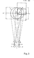
- Figures 2 to 5 schematically represent the geometrical-optical relationships when using different embodiments of the device according to the invention.
- the left eye 21 and the right eye 22, as well as the different prisms are shown such that the through the eye axis and the connecting line between the eyes is in the plane of the drawing.
- the stereoscopic images, as well as their movement on circular paths, were flipped from a plane x - y lying perpendicular to the above-mentioned plane into the drawing plane by 90 0 , so that the prisms and the associated possible movements of the stereoscopic images can be displayed in one figure at the same time.
- the viewing distance is denoted by b, the image center distance by a.
- Dashed lines represent the lines starting from the eye 21, 22 or prism the eye axis or the central line of sight in a given convergence, in which the eyes 21, 22 fix the points 23 and 24 on the plane x - y.
- the dashed lines mark the two largest possible deflections to the right and left when the prism is rotated accordingly.
- the solid line emanating from one eye represents the line of sight that results from the rotation of the prism for which the images, which are also shown with a solid line, come to coincide.
- the direction of the eye itself remains as it is indicated by dash-dotted lines.
- the dashed rectangles represent examples of other image areas that can be covered.
- only one of the holders is provided with a prism 2. It is thus possible to move the image seen by the eye 21 on a circular path 25 by rotating the prism. The radius of the circular path is given by the deflection angle of the prism and the viewing distance. With this embodiment of the device according to the invention, therefore, only a predetermined viewing distance can be used for a given distance between the centers of the two stereoscopic images. With the help of the device, however, it can be adapted to different positions of the stereoscopic images (side by side or one above the other). This is shown schematically in FIG. 2.
- each eye 21, 22 is assigned a prism 2, 26, both prisms having the same deflection angle.
- ent stand by rotating the prisms two offset circular paths 27, 28, on which the images are brought to congruence.
- Adaptation to any viewing distance is possible. Only in the direction of short viewing distances Is there a limitation due to the deflection angle in relation to the center distance of the picture.
- the function of a third embodiment is shown schematically in FIG. 4.
- the deflection angles of the prisms 2, 29 are of different sizes, so that one of the images can be moved on a smaller circular path 30 than the circular path 31 of the other.
- the images are covered in several positions and thus a stereo effect.
- FIG. 5 a fourth embodiment of the device according to the invention is shown in FIG. 5, in which two rotatable prisms 32, 33 are provided for one eye, which can be rotated relative to one another and together with respect to the holder.
- the image of the left eye can be shifted on a circle 34 with a constant radius and the image of the right eye on a circle with a variable radius, the largest possible circle 35 and a somewhat smaller circle 36 being shown in the figure.
- the prisms 32, 33 are opposite, as is indicated by dashed lines, then the radius becomes zero, that is to say the right image is not shifted.
- By rotating the two prisms assigned to one eye in opposite directions an approximately rectilinear movement is obtained.
- An adaptation to different viewing distances and different positions of the stereoscopic images to each other this is particularly advantageous.
- the device according to the invention is not bound to a predetermined arrangement of the stereoscopic images.
- the description mentions images arranged one above the other or next to one another.
- viewing the images, which are offset both horizontally and vertically relative to one another, is readily possible with the device according to the invention.
- the device according to the invention can also be designed in such a way that it can be plugged onto an existing eyeglass, so that use by the visually impaired is facilitated.
Landscapes
- Physics & Mathematics (AREA)
- General Physics & Mathematics (AREA)
- Optics & Photonics (AREA)
Applications Claiming Priority (2)
| Application Number | Priority Date | Filing Date | Title |
|---|---|---|---|
| DE19853516697 DE3516697A1 (de) | 1985-05-09 | 1985-05-09 | Vorrichtung zur betrachtung von stereoskopischen bildern |
| DE3516697 | 1985-05-09 |
Publications (1)
| Publication Number | Publication Date |
|---|---|
| EP0204867A1 true EP0204867A1 (fr) | 1986-12-17 |
Family
ID=6270255
Family Applications (1)
| Application Number | Title | Priority Date | Filing Date |
|---|---|---|---|
| EP85115030A Withdrawn EP0204867A1 (fr) | 1985-05-09 | 1985-11-27 | Dispositif pour regarder des images stéréoscopiques |
Country Status (2)
| Country | Link |
|---|---|
| EP (1) | EP0204867A1 (fr) |
| DE (1) | DE3516697A1 (fr) |
Cited By (3)
| Publication number | Priority date | Publication date | Assignee | Title |
|---|---|---|---|---|
| WO1993025930A1 (fr) * | 1992-06-17 | 1993-12-23 | Suvitie, Juhani | Procede et dispositif pour creer un effet tridimensionnel |
| GB2415265A (en) * | 2004-06-15 | 2005-12-21 | Colin Byron Guppy | Adjustable stereoscopic viewer with rotatable prisms |
| US20140285886A1 (en) * | 2011-11-02 | 2014-09-25 | Jeremy J. DePalma | Stereoscopic viewer |
Families Citing this family (2)
| Publication number | Priority date | Publication date | Assignee | Title |
|---|---|---|---|---|
| FR2743901B1 (fr) * | 1996-01-22 | 1998-02-20 | Drouard Gabriel | Systeme monoculaire optique pour vision d'images stereoscopiques |
| FR2747480B1 (fr) * | 1996-01-22 | 1999-02-26 | Drouard Gabriel | Intermediaire optique monoscopique pour vison d'image stereoscopique |
Citations (6)
| Publication number | Priority date | Publication date | Assignee | Title |
|---|---|---|---|---|
| FR540393A (fr) * | 1921-01-28 | 1922-07-10 | Dispositif permettant la vision stéréoscopique collective | |
| FR825604A (fr) * | 1936-11-23 | 1938-03-09 | Dispositif pour obtenir l'illusion du relief des projections d'images fixes ou animées | |
| FR996753A (fr) * | 1945-06-06 | 1951-12-26 | Dispositif optique permettant d'obtenir le relief par la vision d'une image unique | |
| CH291563A (de) * | 1950-07-22 | 1953-06-30 | Lytax Werke Gmbh | Verfahren zur Raumbildbetrachtung. |
| FR1077547A (fr) * | 1952-12-19 | 1954-11-09 | Instrument d'optique pour vision stéréoscopique | |
| DE6919767U (de) * | 1969-05-16 | 1971-06-16 | Neubauer Gerd | Anordnung zum betrachten zweier stereoskopischer bilder. |
Family Cites Families (5)
| Publication number | Priority date | Publication date | Assignee | Title |
|---|---|---|---|---|
| FR915142A (fr) | 1945-09-28 | 1946-10-28 | Lunettes stéréoscopiques | |
| DE1233617B (de) | 1963-03-11 | 1967-02-02 | Johann Stipek Dipl Ing | Einrichtung zur stereoskopischen Bildbetrachtung |
| US4131342A (en) | 1975-08-22 | 1978-12-26 | Dudley Leslie P | Stereoscopic optical viewing system |
| JPS6035049B2 (ja) | 1979-12-05 | 1985-08-12 | 吉之助 平野 | 映画鑑賞等用立体眼鏡 |
| US4486076A (en) | 1981-10-29 | 1984-12-04 | Sri International | Real time stereo imaging |
-
1985
- 1985-05-09 DE DE19853516697 patent/DE3516697A1/de not_active Withdrawn
- 1985-11-27 EP EP85115030A patent/EP0204867A1/fr not_active Withdrawn
Patent Citations (6)
| Publication number | Priority date | Publication date | Assignee | Title |
|---|---|---|---|---|
| FR540393A (fr) * | 1921-01-28 | 1922-07-10 | Dispositif permettant la vision stéréoscopique collective | |
| FR825604A (fr) * | 1936-11-23 | 1938-03-09 | Dispositif pour obtenir l'illusion du relief des projections d'images fixes ou animées | |
| FR996753A (fr) * | 1945-06-06 | 1951-12-26 | Dispositif optique permettant d'obtenir le relief par la vision d'une image unique | |
| CH291563A (de) * | 1950-07-22 | 1953-06-30 | Lytax Werke Gmbh | Verfahren zur Raumbildbetrachtung. |
| FR1077547A (fr) * | 1952-12-19 | 1954-11-09 | Instrument d'optique pour vision stéréoscopique | |
| DE6919767U (de) * | 1969-05-16 | 1971-06-16 | Neubauer Gerd | Anordnung zum betrachten zweier stereoskopischer bilder. |
Cited By (3)
| Publication number | Priority date | Publication date | Assignee | Title |
|---|---|---|---|---|
| WO1993025930A1 (fr) * | 1992-06-17 | 1993-12-23 | Suvitie, Juhani | Procede et dispositif pour creer un effet tridimensionnel |
| GB2415265A (en) * | 2004-06-15 | 2005-12-21 | Colin Byron Guppy | Adjustable stereoscopic viewer with rotatable prisms |
| US20140285886A1 (en) * | 2011-11-02 | 2014-09-25 | Jeremy J. DePalma | Stereoscopic viewer |
Also Published As
| Publication number | Publication date |
|---|---|
| DE3516697A1 (de) | 1986-11-13 |
Similar Documents
| Publication | Publication Date | Title |
|---|---|---|
| DE4212924C2 (de) | Stereomikroskop | |
| DE10132872B4 (de) | Kopfmontiertes optisches Durchsichtssystem | |
| DE69508960T2 (de) | Stereoskopisches anzeigeverfahren und vorrichtung dazu | |
| DE3523639C2 (fr) | ||
| DE4417768A1 (de) | Verfahren und Vorrichtung zum Projizieren von Bildinformationen bei Personen mit durch eine Abweichung der Stellung ihrer Sehachse verursachten Störungen des Sehens | |
| EP0492044A1 (fr) | Appareil destiné à l'essai de la fonction visuelle | |
| EP0362692A2 (fr) | Lunettes pour regarder sans fatigue le plan d'images d'un écran ou autres plans d'images | |
| DE19543598B4 (de) | Optische Systeme | |
| EP0204867A1 (fr) | Dispositif pour regarder des images stéréoscopiques | |
| DE4004248C2 (de) | Binokulare Sehhilfe | |
| DE2624372C3 (de) | Vorrichtung zur photogrammetrischen Wiedergabe | |
| DE2021864B2 (de) | Stereomikroskop nach greenough | |
| DE4010874A1 (de) | Stereoskopische betrachtungsvorrichtung | |
| DE4003211C2 (de) | Augenfundus-Stereokamera | |
| DE3886948T2 (de) | Videosystem mit einer bilderfassungsanordnung und einer bildwiedergabeanordnung. | |
| DE4113536C2 (fr) | ||
| DE3624835A1 (de) | Kopfgetragenes spiegelstereoskop | |
| WO1996031797A1 (fr) | Procede et dispositif de generation d'images en 3d | |
| DE653859C (de) | Sucher fuer photographische Kammern | |
| DE3343781A1 (de) | Verfahren zur erzielung eines plastisch-raeumlichen bildeindruckes bei der betrachtung eines flaechenhaften bildes sowie anordnung zur durchfuehrung des verfahrens | |
| DE2733667A1 (de) | Positioniersystem der optischen achsen einer bildpaar-betrachtungsvorrichtung, und bildpaar-betrachtungsvorrichtungen mit einem solchen system | |
| DD290064A5 (de) | Operationsmikroskop mit mitbeobachtereinrichtung | |
| DE1957846A1 (de) | Apparat zur stereoskopischen Wiedergabe | |
| DE961311C (de) | Stereoprojektor mit Doppelobjektiven und Polarisationsfiltern | |
| DE926712C (de) | Kinematographische Aufnahmeeinrichtung zur wahlweisen Herstellung von Stereobildern und Flachbildern |
Legal Events
| Date | Code | Title | Description |
|---|---|---|---|
| PUAI | Public reference made under article 153(3) epc to a published international application that has entered the european phase |
Free format text: ORIGINAL CODE: 0009012 |
|
| AK | Designated contracting states |
Kind code of ref document: A1 Designated state(s): DE FR GB IT |
|
| 17P | Request for examination filed |
Effective date: 19870119 |
|
| 17Q | First examination report despatched |
Effective date: 19880108 |
|
| STAA | Information on the status of an ep patent application or granted ep patent |
Free format text: STATUS: THE APPLICATION IS DEEMED TO BE WITHDRAWN |
|
| 18D | Application deemed to be withdrawn |
Effective date: 19880519 |
|
| RIN1 | Information on inventor provided before grant (corrected) |
Inventor name: TIMM, HORST, ING. GRAD. |