EP0206612A2 - Adapteur de porte-outil - Google Patents
Adapteur de porte-outil Download PDFInfo
- Publication number
- EP0206612A2 EP0206612A2 EP86304381A EP86304381A EP0206612A2 EP 0206612 A2 EP0206612 A2 EP 0206612A2 EP 86304381 A EP86304381 A EP 86304381A EP 86304381 A EP86304381 A EP 86304381A EP 0206612 A2 EP0206612 A2 EP 0206612A2
- Authority
- EP
- European Patent Office
- Prior art keywords
- adaptor
- tool member
- tool
- sleeve
- spindle
- Prior art date
- Legal status (The legal status is an assumption and is not a legal conclusion. Google has not performed a legal analysis and makes no representation as to the accuracy of the status listed.)
- Withdrawn
Links
- 230000013011 mating Effects 0.000 claims 1
- 230000002093 peripheral effect Effects 0.000 claims 1
- 238000005553 drilling Methods 0.000 description 2
- 238000000034 method Methods 0.000 description 2
- 238000010079 rubber tapping Methods 0.000 description 2
- 230000000694 effects Effects 0.000 description 1
- 238000003780 insertion Methods 0.000 description 1
- 230000037431 insertion Effects 0.000 description 1
- 238000006467 substitution reaction Methods 0.000 description 1
Images

Classifications
-
- B—PERFORMING OPERATIONS; TRANSPORTING
- B23—MACHINE TOOLS; METAL-WORKING NOT OTHERWISE PROVIDED FOR
- B23B—TURNING; BORING
- B23B31/00—Chucks; Expansion mandrels; Adaptations thereof for remote control
- B23B31/02—Chucks
- B23B31/10—Chucks characterised by the retaining or gripping devices or their immediate operating means
- B23B31/107—Retention by laterally-acting detents, e.g. pins, screws, wedges; Retention by loose elements, e.g. balls
- B23B31/1071—Retention by balls
Definitions
- This invention relates to an adaptor for connecting tool-holders to rotating spindle machines whereby the tool-change of cutting tools and tool-holder may be achieved using robot facilities.
- the invention particularly relates to the category of machines using multi-spindle heads whereby it is possible to effect a tool-change without manual intervention.
- These machines are of the transfer line type, having a multitude of work spindles capable of performing drilling, reaming and tapping operations principally. However, it is often necessary to change one or more of the tools either for the purposes of replacing the tool because it is blunt or for changing the purpose of the tool, for instance reaming or tapping following drilling.
- an adaptor for a rotary machine comprises a spindle member for attachment to or forming a part of said spindle of the machine and a tool member, the spindle member having an axially slidable sleeve around it which has an annular inclined surface to act, on axial movement of the sleeve, on one or more gripping elements extending through apertures in the side of the spindle member into a bore thereof, which bore is adapted to receive the tool member, the gripping elements being arranged to act on a frusto-conical surface of the tool member so as to draw the tool member into the spindle member.
- the slidable sleeve is resiliently biassed towards a position in which it grips the tool member.
- spring means is provided to eject the tool member from the spindle member once the tool member has been released by the gripping elements.
- the spring means may include a piston which, having ejected the tool member, adopts a position in the bore of the spindle member in which it prevents the gripping means from being displaced inwardly by the sleeve and therefore prevents the sleeve from returning to its previous gripping position.
- the piston may act not on the gripping means but on a separate locking means to retain the sleeve in its axially displaced position when the piston has ejected the tool member.
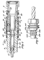
- Figure 1 shows an adaptor 1 which comprises a spindle member 3 and a tool member 5.
- the tool member may be in the form of a chuck or collet to grip a tool as shown in the drawing or indeed it may in fact be the tool itself.
- the tool member 5 has two conical surfaces 7 and 9 which are adapted to co-operate with corresponding conical surfaces 11 and 13 formed in a bore 15 of the spindle member 3 when the tool member 5 is inserted into the spindle member 3 as shown in the drawing, the interengaging surfaces 9, 13 and 7, 11 ensure that the tool member 5 is concentric with the spindle member 3.
- the spindle member 3 is itself connectible to a spindle of a rotary machine not shown.
- the spindle member 3 may be integral with the spindle of the machine. In the drawing however it is shown as a separate element connectible to the spindle of the machine by set screw 17.
- a sleeve 19 is disposed on, and surrounds, the spindle member 3 and is urged axially by a spring 21 towards a flange 23 formed on the spindle member 3.
- the sleeve 19 is provided with a coned surface 25 and a circular groove 27.
- a number of apertures 31 disposed equally around the circumference of the spindle member 3, house gripping elements 33 which in the present instance are in the form of balls.
- the balls 33 are acted upon by the conical surface 25 of the sleeve 19 and urged radially inwardly by the spring means 21.
- the gripping elements 33 act on a conical surface 35 formed on the tool member 5.
- the surface 35 is inclined such that the radially inward pressure of the gripping elements or balls 33 tends to draw the tool member 5 into the spindle member 3.
- the sleeve 19 is provided with a groove 41 facilitating the gripping thereof by an automatically controlled means.
- the groove 41 is gripped by said automatic means and the sleeve 19 is drawn to the right in the drawing.
- a spring 43 which acts upon a piston 45.
- the piston 45 is arranged so as to eject the tool member 5 when it is released by the gripping elements 33.
- the piston 45 pushes the tool member 5 out of the spindle member 3 and in so doing positions itself underneath the balls 33 thereby preventing them from returning towards their gripping position once the tool member 5 has been withdrawn.
- the sleeve 19 cannot return to the gripping position shown in the drawings.
- the sleeve 19 is located by the balls 33 co-operating with the circular groove 27.
- the tool member 5 is also provided with automatic handling facilities by the provision of a grooved ring 47 thereof.
- the ring 47 and the tool member 5 are each provided with a circumferential groove in which balls 49 are located enabling the ring to rotate around the tool member 5. This allows the tool member 5 to rotate about its axis slightly as may be necessary when it is being gripped via the gripping ring 47 and being inserted into the spindle member 3. Such rotation may be necessary to align the grooves 39 with the balls 37, and that such rotation will be brought about by the fact that the bottoms of the grooves 39 are radiused to engage the balls 37 when the tool member 5 is inserted.
- the sleeve 19 is provided at its ends with seals 51, 53 to prevent the ingress of dirt. Similarly the ring 47 is provided with a seal 55.
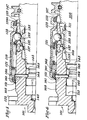
- the second embodiment of the adaptor 101 comprises a spindle member 103 and a tool-holder 105, the tool-holder 105 having axially spaced conical surfaces 107, 109 which co-operate with corresponding conical surfaces 111 and 113 formed in a bore 115 of the spindle member 103, the interengaging surfaces 109, 113 and 107, 111 ensuring that the tool-holder 105 is concentric with the spindle member 103.
- the spindle member 103 is itself connectible to a spindle of a rotary machine (not shown), as previously described.
- a sleeve 119 is disposed on, and surrounds, the spindle member 103 and is urged axially by a spring 121 towards a flange 123 formed on the spindle member 103.
- the sleeve 119 is provided with an internal coned surface 125.
- the gripping elements 133 act on a conical surface 135 formed on the tool-holder 105.
- the surface 135 is inclined such that the radially inward pressure of the gripping elements or balls 133 tends to draw the tool-holder 105 into the spindle member 103.
- the tool-holder 105 may also be provided with a circumferential bar code label, as at 170, for automated tool identification.
- splines or pins may replace the balls 137.
- the sleeve 119 is provided with a groove 141, corresponding in purpose with groove 41 of the first embodiment.
- the groove 141 is gripped and the sleeve 119 is drawn to the right, as seen in Figure 4.
- a spring 143 which acts upon a piston 145.
- the piston 145 is arranged so as to eject the tool-holder 105 when it is released by the gripping elements 133.
- the piston 145 pushes the tool-holder 105 out of the spindle member 103, as seen in Figure 5.
- a radially movable pin 160 is positioned in a bore 161 in the spindle member 103 and extends radially inwardly into a circumferential groove 163 formed in the piston 145 when the tool-holder 105 is fully inserted into the spindle member 103.
- a ramp surface 164 will engage the end of the pin to urge it outwardly as the piston 145 moves to the right, and further movement brings a land portion 165 into alignment with the pin 160 to retain it in its radially outwardly displaced position.
- the tool-holder 105 is also provided with automatic handling facilities by the provision of a grooved ring 147 thereof.
- the ring 147 and the tool-holder 105 are each provided with a circumferential groove in which balls 149 are located enabling the ring to rotate around the tool-holder 105. This allows the tool-holder 105 to rotate about its axis slightly during insertion into the spindle member 103, as previously described.
- the end face of the tool-holder will contact the piston 145 and urge it leftwards as seen in the drawings, against the spring 143.
- the radially inner end of the pin 160 is opposite the circumferential groove 163 in the piston 145.
- the conical surface 162 then forces the pin 160 inwardly and the sleeve moves to the left, urged by spring 121, and the gripping elements 133 engage the tool-holder 105 to retain it in the spindle member. It should be noted that the gripping elements engage after the aligning surfaces have mated, and thus engagement of the gripping elements cannot interfere with the alignment of the tool.
- Seals 151, 153 are provided to prevent the ingress of dirt into the mechanism.
Landscapes
- Engineering & Computer Science (AREA)
- Mechanical Engineering (AREA)
- Automatic Tool Replacement In Machine Tools (AREA)
- Gripping On Spindles (AREA)
Applications Claiming Priority (2)
| Application Number | Priority Date | Filing Date | Title |
|---|---|---|---|
| GB8514693 | 1985-06-11 | ||
| GB858514693A GB8514693D0 (en) | 1985-06-11 | 1985-06-11 | Tool-holder adaptor |
Publications (2)
| Publication Number | Publication Date |
|---|---|
| EP0206612A2 true EP0206612A2 (fr) | 1986-12-30 |
| EP0206612A3 EP0206612A3 (fr) | 1988-08-31 |
Family
ID=10580520
Family Applications (1)
| Application Number | Title | Priority Date | Filing Date |
|---|---|---|---|
| EP86304381A Withdrawn EP0206612A3 (fr) | 1985-06-11 | 1986-06-09 | Adapteur de porte-outil |
Country Status (2)
| Country | Link |
|---|---|
| EP (1) | EP0206612A3 (fr) |
| GB (1) | GB8514693D0 (fr) |
Cited By (3)
| Publication number | Priority date | Publication date | Assignee | Title |
|---|---|---|---|---|
| GB2199269A (en) * | 1986-12-29 | 1988-07-06 | Smith Tool Int Corp T M | Quick change spindle adapter for tool holder |
| JP2014210337A (ja) * | 2013-04-18 | 2014-11-13 | ビルツ ヴェルクツォイクファブリーク ゲゼルシャフト ミット ベシュレンクテル ハフツング ウント コンパニーコマンディートゲゼルシャフト | 用具保持器用の素早い交換システム |
| EP2937181A1 (fr) * | 2014-04-22 | 2015-10-28 | HILTI Aktiengesellschaft | Porte-outil |
Family Cites Families (4)
| Publication number | Priority date | Publication date | Assignee | Title |
|---|---|---|---|---|
| US3652099A (en) * | 1970-02-19 | 1972-03-28 | Otto Bilz | Drill chuck |
| US3788658A (en) * | 1972-08-14 | 1974-01-29 | Erickson Tool Co | Instant change tool holder |
| SE374288B (fr) * | 1973-06-04 | 1975-03-03 | Eminentverktyg Ab | |
| DE3326615A1 (de) * | 1983-07-23 | 1985-01-31 | Otto Bilz, Werkzeugfabrik, 7302 Ostfildern | Werkzeug oder werkzeughalter, insbesondere fuer die zerspanende bearbeitung auf numerisch gesteuerten bearbeitungszentren |
-
1985
- 1985-06-11 GB GB858514693A patent/GB8514693D0/en active Pending
-
1986
- 1986-06-09 EP EP86304381A patent/EP0206612A3/fr not_active Withdrawn
Cited By (8)
| Publication number | Priority date | Publication date | Assignee | Title |
|---|---|---|---|---|
| GB2199269A (en) * | 1986-12-29 | 1988-07-06 | Smith Tool Int Corp T M | Quick change spindle adapter for tool holder |
| GB2199269B (en) * | 1986-12-29 | 1990-12-19 | Smith T M Tool Int | Quick change spindle adapter for tool holder |
| JP2014210337A (ja) * | 2013-04-18 | 2014-11-13 | ビルツ ヴェルクツォイクファブリーク ゲゼルシャフト ミット ベシュレンクテル ハフツング ウント コンパニーコマンディートゲゼルシャフト | 用具保持器用の素早い交換システム |
| EP2792439A3 (fr) * | 2013-04-18 | 2015-07-01 | Bilz Werkzeugfabrik GmbH & Co. KG | Système de changement rapide pour un porte-outil |
| US9573195B2 (en) | 2013-04-18 | 2017-02-21 | Bilz Werkzeugfabrik Gmbh & Co. Kg | Quick-change system for a tool holder |
| EP2937181A1 (fr) * | 2014-04-22 | 2015-10-28 | HILTI Aktiengesellschaft | Porte-outil |
| WO2015162109A1 (fr) * | 2014-04-22 | 2015-10-29 | Hilti Aktiengesellschaft | Porte-outil |
| US10112239B2 (en) | 2014-04-22 | 2018-10-30 | Hilti Aktiengesellschaft | Tool holder |
Also Published As
| Publication number | Publication date |
|---|---|
| GB8514693D0 (en) | 1985-07-10 |
| EP0206612A3 (fr) | 1988-08-31 |
Similar Documents
| Publication | Publication Date | Title |
|---|---|---|
| KR100289138B1 (ko) | 공작기계의 자동공구교환장치 | |
| US5810366A (en) | Tool-less machine tool chuck | |
| US4436463A (en) | Quick change tooling system | |
| US11801561B2 (en) | Tool turret | |
| WO1997048513A9 (fr) | Mandrin pour machine-outil sans outil | |
| EP3546098B1 (fr) | Ensemble de serrage de collet à changement rapide | |
| US3999769A (en) | Tool holder for machine tools | |
| US5613929A (en) | Machine tool with bar-spindle and DIN standard toolholder changer | |
| JP2774161B2 (ja) | 工作機械主軸用工具アダプタ | |
| US4777714A (en) | Quick-change mount for chucks | |
| US4767246A (en) | Quick-release tool holding device | |
| US4550922A (en) | Workholder | |
| CN1185764A (zh) | 反离心力卡头及安装系统 | |
| EP0206612A2 (fr) | Adapteur de porte-outil | |
| EP0564296B1 (fr) | Appareil pour la broche principale d'une machine outil | |
| EP0807481B1 (fr) | Dispositif de fixation d'un outil | |
| US4812091A (en) | Exchange system on an irremovable machining center | |
| US4685687A (en) | Workholder | |
| US7347807B2 (en) | Machine tool and method for changing tools on this machine tool | |
| JPH0137850Y2 (fr) | ||
| US6953198B2 (en) | Short pull-back chuck | |
| CN111230147B (zh) | 保持架加工用车床 | |
| JPH0236648Y2 (fr) | ||
| EP0218756B1 (fr) | Porte-outil | |
| JPS5856111Y2 (ja) | クイツクチエンジホルダ |
Legal Events
| Date | Code | Title | Description |
|---|---|---|---|
| PUAI | Public reference made under article 153(3) epc to a published international application that has entered the european phase |
Free format text: ORIGINAL CODE: 0009012 |
|
| AK | Designated contracting states |
Kind code of ref document: A2 Designated state(s): BE DE FR GB IT SE |
|
| PUAL | Search report despatched |
Free format text: ORIGINAL CODE: 0009013 |
|
| RHK1 | Main classification (correction) |
Ipc: B23B 31/22 |
|
| AK | Designated contracting states |
Kind code of ref document: A3 Designated state(s): BE DE FR GB IT SE |
|
| STAA | Information on the status of an ep patent application or granted ep patent |
Free format text: STATUS: THE APPLICATION IS DEEMED TO BE WITHDRAWN |
|
| 18D | Application deemed to be withdrawn |
Effective date: 19890304 |
|
| RIN1 | Information on inventor provided before grant (corrected) |
Inventor name: PARRY, REGINALD SIDNEY |