EP0208109B1 - Machine agricole pour récolter - Google Patents
Machine agricole pour récolter Download PDFInfo
- Publication number
- EP0208109B1 EP0208109B1 EP86107152A EP86107152A EP0208109B1 EP 0208109 B1 EP0208109 B1 EP 0208109B1 EP 86107152 A EP86107152 A EP 86107152A EP 86107152 A EP86107152 A EP 86107152A EP 0208109 B1 EP0208109 B1 EP 0208109B1
- Authority
- EP
- European Patent Office
- Prior art keywords
- nozzle
- algorithm
- value
- control
- spout
- Prior art date
- Legal status (The legal status is an assumption and is not a legal conclusion. Google has not performed a legal analysis and makes no representation as to the accuracy of the status listed.)
- Expired - Lifetime
Links
- 238000003306 harvesting Methods 0.000 title claims description 20
- 239000004459 forage Substances 0.000 claims abstract description 10
- 238000012360 testing method Methods 0.000 claims description 15
- 239000000463 material Substances 0.000 claims description 2
- 230000006870 function Effects 0.000 abstract description 6
- 238000004422 calculation algorithm Methods 0.000 description 110
- 230000033001 locomotion Effects 0.000 description 32
- 239000011248 coating agent Substances 0.000 description 9
- 238000000576 coating method Methods 0.000 description 9
- 230000000694 effects Effects 0.000 description 7
- 238000000034 method Methods 0.000 description 6
- 230000004044 response Effects 0.000 description 6
- 238000010586 diagram Methods 0.000 description 5
- 230000008569 process Effects 0.000 description 5
- 230000001960 triggered effect Effects 0.000 description 5
- 230000037430 deletion Effects 0.000 description 3
- VLCYCQAOQCDTCN-UHFFFAOYSA-N eflornithine Chemical compound NCCCC(N)(C(F)F)C(O)=O VLCYCQAOQCDTCN-UHFFFAOYSA-N 0.000 description 3
- 238000012986 modification Methods 0.000 description 3
- 230000004048 modification Effects 0.000 description 3
- 230000004913 activation Effects 0.000 description 2
- 230000005540 biological transmission Effects 0.000 description 2
- 230000008859 change Effects 0.000 description 2
- 238000012937 correction Methods 0.000 description 2
- 238000012217 deletion Methods 0.000 description 2
- 239000012530 fluid Substances 0.000 description 2
- 230000007246 mechanism Effects 0.000 description 2
- 241000132536 Cirsium Species 0.000 description 1
- 238000013459 approach Methods 0.000 description 1
- 238000004364 calculation method Methods 0.000 description 1
- 239000003990 capacitor Substances 0.000 description 1
- 238000004590 computer program Methods 0.000 description 1
- 230000001934 delay Effects 0.000 description 1
- 230000003111 delayed effect Effects 0.000 description 1
- 238000011161 development Methods 0.000 description 1
- 230000002996 emotional effect Effects 0.000 description 1
- 230000001939 inductive effect Effects 0.000 description 1
- 230000003287 optical effect Effects 0.000 description 1
- 230000036316 preload Effects 0.000 description 1
- 238000012545 processing Methods 0.000 description 1
- 230000007480 spreading Effects 0.000 description 1
- 238000012546 transfer Methods 0.000 description 1
Images


Classifications
-
- A—HUMAN NECESSITIES
- A01—AGRICULTURE; FORESTRY; ANIMAL HUSBANDRY; HUNTING; TRAPPING; FISHING
- A01D—HARVESTING; MOWING
- A01D43/00—Mowers combined with apparatus performing additional operations while mowing
- A01D43/06—Mowers combined with apparatus performing additional operations while mowing with means for collecting, gathering or loading mown material
- A01D43/07—Mowers combined with apparatus performing additional operations while mowing with means for collecting, gathering or loading mown material in or into a trailer
Definitions
- the invention relates to a forage harvesting machine with a connection piece which ejects the crop onto a carriage which receives it and which can be pivoted relative to the harvesting machine and the carriage by means of a swivel drive and an electronic control system controlling the latter, and with the features of the preamble of claim 1.
- Such a forage harvesting machine is known from EP-A-0 070 340.
- separate hydraulic control valves are assigned to the electronic control system and the manual control system for the pivot drive of the nozzle.
- This arrangement is such that the electronic control system, which automatically controls the swivel drive of the nozzle, is interrupted in its effectiveness by the manual control by the electrical line connection between the electronic control system and the associated, electro-hydraulic valve when the manual control is actuated interrupted by manual control.
- the electrical line connection is closed again and the electronic control system is brought into effect.
- the known arrangement thus requires two separate electro-hydraulic control valves. It is designed so that the manual control simultaneously switches the effect of the electronic control system on and off.
- the swivel drive is controlled as a function of the signals from the sensor means via the mode means of the computer program.
- control means for manual control not the work of the computer but only the effect of its mode means interrupted, with the help of the test means provided in the program of the computer.
- test devices can independently determine the beginning and the end of manual control and thus automatically deactivate the mode devices.
- the computer Since the computer also continues to receive the signals from the sensor means during manual control and processes these signals in accordance with the program, the actual position of the nozzle can be determined when the manual control is ended and, depending on this, the swivel drive can be actuated so that the nozzle automatically returns to the swivel range can be moved, in which the mode means then automatically take over control of the nozzle again automatically within the predetermined swivel angle range and in a targeted orientation to the carriage.
- the operator of the forage harvesting machine can at any time bring the nozzle into any desired position by hand, which is also far outside the usual angular range. If the purpose of this manual intervention is fulfilled, the operator does not have to worry about the actual position of the nozzle nor about its further movement in order to load the carriage evenly. This makes operation much easier. Since the nozzle is immediately returned to the aligned position after this intervention, the automatic operation is restored much faster and more effectively. This significantly improves the effectiveness of the system.
- a harvesting machine 10 pulled by agricultural tractors or a self-propelled harvesting machine (not shown) is provided, which has a pull rod which is withdrawn from view through the rotatable crop discharge nozzle.
- the drawbar 16 of a carriage 18 is attached to the pull rod so that the carriage 18 receives the material expelled from the nozzle 14.
- a nozzle angle is defined as the relative angle between the nozzle 14 and the longitudinal axis of the harvesting machine 10.
- a drawbar angle is defined as the relative angle between the vehicle drawbar 16 and the longitudinal axis.
- a control system 22 is shown schematically in FIG. 2. This serves to control the position of the nozzle 14, either automatically or manually.
- the control takes place via an electro-hydraulic circuit 24.
- the circuit 24 comprises a conventional double-acting fluid motor 26 which moves the nozzle 14 either to the left or to the right Depends on the fluid that is supplied by a pilot operated directional control valve 28.
- This is connected to a pump pressure line 30 and a sump line 32.
- Solenoid controlled pilot valves 34 and 36 for left and right movement actuate directional control valve 28 in response to control signals provided via control lines 38 and 40 for left and right movement, respectively.
- circuit 24 includes a pilot operated bypass valve 42 which is controlled by a solenoid operated valve 44 which in turn receives control signals via a control line 46. It is noted that it is within the scope of the present invention to replace the hydraulic motor 26 with an electrically driven motor and the hydraulic circuit 24 with an electrical control circuit.
- a switching module 50 for manual direction control comprises a double-pole and double-path switch 51 which is currently in effect and in which one side of both poles is connected to the +12 volt connection of the vehicle battery or another power supply.
- Switch contacts 52, 54 for left-hand control and right-hand control are connected to the assigned inputs or control lines 38 and 40, respectively.
- open contacts 56, 58 can be connected to the control line 46 in the middle position, so that the valve 44 is actuated to close the bypass valve 42 whenever the switch 51 contacts the contact 52 or the contact 54.
- a sensor 60 for the nozzle angle and a sensor 62 for the drawbar angle preferably each consist of conventional rotary potentiometers which are connected that they generate voltages that are representative of the nozzle angle or drawbar angle.
- a wagon position signal is obtained by using an optical sensing system for the wagon position as described in the aforementioned GB-OS 20 73 914.
- the relevant voltage for the nozzle angle, which is generated by the sensor 60 can be understood as a feedback signal for the automatic control circuit 64.
- This circuit 64 generates control signals in the lines 66 and 68 and in the output line 70 depending on the position of the drawbar and the nozzle, for left-hand or right-hand control.
- the output lines 66 to 70 are connected to control lines 38, 40 and 46, respectively.
- the sensors 60 and 62 are connected to the inputs of a conventional multiplexor 72.
- the potentiometers 74, 76, 78 are coupled to the input pins 1, 5 and 2 of the multiplexor 72 and deliver adjustable calibration signals, which are explained in more detail below.
- the potentiometers for the nozzle and the drawbar have resistance ranges from zero to the end of the scale, which extend over 340 o with a blind spot range of 20 o .
- the resistance range is located so that half of the full resistance scale corresponds to a straight position of the nozzle or the drawbar.
- two points are provided within the full resistance scale range, one approximately 5 o from the zero resistance point and the other approximately 1 o from the full scale end point of the resistance. These are used to define limits for the electrical or working ranges of the potentiometers.
- the Stutzenpotentiometer 60 is preferably coupled via a gearbox with the connecting piece, so that an angular region of the connection position of approximately 143 o the full scale resistance range of the potentiometer or the work area 334 corresponds to o. That means, that the working range for the nozzle potentiometer 60 corresponds to a range of nozzle positions of 140 o .
- the drawbar potentiometer 62 is coupled directly to the drawbar 16, so that there is a 1: 1 relationship between the drawbar angle range and the angular range of the drawbar potentiometer 62.
- Upward and downward biasing resistors are connected to the sliding contacts of potentiometers 74, 76 and 78.
- the pre-tensioning resistors are selected so that in the case of an open circular state in the sliding contact line, the voltages applied to the multiplexor 72 correspond to a calibration setting in the middle.
- the preload resistors are selected so that the voltage at the sliding contact that occurs in an open circular state corresponds to the normal width of a typical carriage.
- the multiplexor 72 feeds the selected signals to the analog input ANO of a microprocessor 80.
- a microprocessor 80 This includes a central processor unit, a ROM program memory, a RAM data memory and entry and exit points.
- the microprocessor ROM stores instructions that include the encoded information that controls the activities of the central processor unit.
- the microprocessor RAM stores encoded data information by the central processor unit have been treated.
- the central processor unit reads each instruction from the program memory in accordance with a predetermined sequence in order to control the data processing activities.
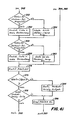
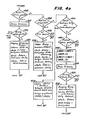
- the microprocessor program which is described below, is represented by the flow cards according to FIGS. 4a to 4p, 5, 7 and 8.
- the control signals generated by the microprocessor 80 are fed to the address inputs (not shown) of the multiplexor 72, the relay driver units 82 and 84 and the LED driver units 85, 86, 87 and 88.
- the latter driver units drive corresponding indicator lamps for left and right control 105 and 106, for left and right nozzle positions and indicator lamps 107 and 108 for left and right tiller positions.
- the lamps are preferably arranged on a board that can be observed by the driver.
- Relay drivers 82 and 84 drive relays 90 and 92 in response to control signals generated by microprocessor outputs P10 and P11 to actuate associated pilot valves 36 and 34 of circuit 24.
- Diodes D1 and D2 provide power to relays 94 and pilot valve 44 whenever relays 90 and 92 are turned on.
- Diode D3 provides a path for inductive feedback current from relay 94.
- drivers 82 and 84 can be assumed to include similar feedback diodes.
- the anodes of the diodes D1 and D2 are each connected to the relay sensor inputs PO4 and PO5 of the microprocessor 80 via identical voltage limiting and filter circuits 96 and 98.
- Circle 98 is shown in detail. It comprises resistors R1, R2 and R3, a Zener diode D4 (eg of the type IN 4735) and a capacitor C1, which is connected as shown.
- Circles 96 and 98 sense the microprocessor 80 when it is switched on of lines 66 and 88, which is caused either manually by actuation of switch 51 or automatically by the signals generated at microprocessor outputs P10 and P11.
- the circuits 96 and 98 protect the microprocessor 80 against excessive voltages and stray currents.
- Connection circuits 100 and 102 and a switch 104 can be connected to the microprocessor, so that the operation of the circuit 64 can be adapted to special situations by opening or short-circuiting different connection circuits. For example, a trim mode operation for the nozzle can be activated or deactivated by opening or closing the switch 104.
- the algorithm begins at step 202 depending on a hardware reset to an external interrupt or a timer interrupt.
- steps 204 through 208 external interruptions or timer interruptions are excluded and the random access memory RAM is flushed.
- a hardware timer (not shown) that is integral to microprocessor 80 is triggered. This hardware timer periodically generates a flag signal (e.g., every 80 milliseconds) which is used to generate a desired time interval for use with the software timers to be described later, which are described below.
- a software timer used for feedback and a software timer used to delay the deletion mode is started. After that the position or the angle of the nozzle is read out by the sensor 60 at step 214. At step 216, left and right understeer registers are triggered to values representing 3 o . This 3 o is the assumed value by which the nozzle overflows the actuated position.
- the main loop begins with a manually operated test routine 217. This, which is described in detail with reference to FIG. 8, sets or triggers manual identification signals depending on whether or not any signal is present at relay sensing inputs PO4 PO5, and due to manual actuation of the switching module 50.
- step 218 This leads him to stage 268 if a flag signal is not set on the hardware timer. Otherwise, the algorithm proceeds to steps 220 through 226.
- the deceleration timer for cornering and the deceleration timer for coating mode are switched down step by step, provided they have not already been switched down to the zero value.
- the delay timer namely the cornering timer 1
- the delay timer is used to keep the neck in a target position which is as close as possible to the center of the car and to prevent the stroking mode from being activated for a period of 15 seconds after the end of cornering through the harvester (see steps 378,384,386 and 406). This ensures that the wagon is fairly aligned with the longitudinal axis of the harvester before the nozzle is allowed to deviate from the center of the wagon over a larger angle.
- the coating mode time delay (timer 2) is used to hold the nozzle in each coating mode position for 15 seconds (see steps 508, 516, 528) and to prevent the coating mode from being operated until 15 seconds after Completion of a manual or automatic nozzle movement (see step 482), by means of which the nozzle is brought into the central 25% area of the window receiving the crop.
- a display timer (timer 3) is incrementally turned down (230) or turned on (232) as determined by step 228 to provide a bit of data that reciprocates at a rate of 1-2 Hz commutes. This data bit is used to trigger a flickering display device [not shown].
- Steps 243 through 236 gradually reset a delay timer (timer 4) for a relay for diagnostic purposes for the relay.
- Step 237 determines whether an error flag has been set for the nozzle potentiometer at step 312. If not, the algorithm proceeds to step 238. If it does, the algorithm is directed to step 237A. There, a timer for 4 seconds (timer 5) or a delay timer for the error of the nozzle potentiometer, which was started in step 312, is operated step by step. Thereafter, step 237B directs the algorithm to step 238 if the timer 5 has not expired. Otherwise, the algorithm proceeds to step 237C, which sets a delay flag for an error in the nozzle potentiometer. This flag is not set unless the error flag for the nozzle potentiometer in step 312 is continuous for the duration of 4 seconds remains.
- Step 238 leads the algorithm to step 240 if an understeer delay timer (timer 6) is running. Otherwise, the algorithm is directed to step 246.
- the timer 6 preferably has a duration of approximately one second and is started when the nozzle is commanded to stop moving (see step 508).
- the understeer time delay is used to delay the recalculation of the right and left understeer values UNDR and UNDL, respectively, in step 504 until the nozzle has had enough time to creep into the stop position after an automatic nozzle movement.
- Step 240 increments the understeer delay timer, and step 246 triggers the hardware timer. After step 246, the test routine for manual actuation of FIG. 8 is repeated at step 268.
- Step 270 removes the multiplexor error flag.
- Steps 272 through 278 then take effect to write a multiplexor error flag in step 278 if the input pin 4 of the multiplexor 72 is not properly grounded, if the voltage at the input pin 12 of the multiplexor and at the limit input Vth of the microprocessor 80 is not 2 volts or if the voltage at pin 13 of multiplexor 72 is not 5 volts. Otherwise, the algorithm proceeds to step 286.
- the grounded input (pin 4) of the multiplexor 72 and the 5 volt input (pin 13 of the multiplexor 72) are selected so that the addressing code is "all 1" and the address code of the others is equal to "all 0".
- step 294 directs the algorithm to step 302 where a drawbar potentiometer error value is set. From there, the amount o ends outside the region of 334 electrical Deichselpotentiometers 62 lies is indexed to 303 when the tongue position value corresponds TPTONG of step 292 with a value. Since the drawbar is normally physically prevented from moving beyond 90 o from the straight-ahead position, very low or very large potentiometer values on the drawbar scale can be interpreted as values due to a failure of the potentiometer.
- step 294 directs the algorithm to step 296.
- the potentiometer error signal for the drawbar is deleted.
- TCAL is the tongue calibration value from calibration potentiometer 76.
- the TPTONG value is then, if this value is larger than +55 or smaller than -55 o o, set equal to +55 o and -55 o. This prevents excessive nozzle rotation if the tiller can swing freely or is torn up.
- step 8 is repeated at step 303.
- step 304 the nozzle angle or position value TSPOU is obtained from the sensor 60.
- step 306 the algorithm is directed to step 338, if the difference between the current and the previous signal representing the nozzle angle is larger than a threshold value corresponding to a Stutzenwinkelgechwindtechnik of example 18 o per second. Since the nozzle is normally moved more slowly than this angular velocity, rapid changes in the values of the nozzle potentiometer indicate that the nozzle is unscrewed outside the electrical operating range of the nozzle potentiometer 60. Step 306 thus serves to determine whether the nozzle has been rotated beyond the electrical effective range of the potentiometer 60, which would lead to an abrupt change in the signal generated by the potentiometer 60.
- step 308 which directs the algorithm to step 314 if an error indicator for the nozzle potentiometer has been previously set at step 312. If not, the algorithm proceeds from step 308 to step 310. This directs the algorithm to step 320 if the signal from the potentiometer 60 is within the 334 o working range. Otherwise, the algorithm proceeds to step 312. This means that step 312 sets an error flag for the nozzle potentiometer and starts the delay timer for the potentiometer error if the signal from potentiometer 60 is outside the 334 o range. After step 312, the algorithm proceeds to step 328.
- Step 320 directs the algorithm to step 328 if a twist error flag has been set (step 324). Otherwise, it goes to step 322 where a PREHEM value is stored to indicate whether the potentiometer 60 was last in the high half of the resistance range or in the lower half. After step 322, the process continues to step 328.
- step 308 directs the algorithm to step 314, it determines whether the value on the nozzle potentiometer 60 is within the 334 o working range. If not, the process continues to step 328. If it is, it means that potentiometer 60 has been returned to a position within the working range so that the algorithm proceeds to step 316. Here it is determined whether the signal from the potentiometer 60 corresponds to the actual position of the nozzle potentiometer, within the same hemisphere in which the signal was previously. If not, it is indicated that the neck has been rotated continuously from one atmosphere of the working area of the potentiometer 60 and back into the other hemisphere without going through the central neck position. A corresponding error signal is then set in step 324.
- step 318 the error indicator for the nozzle potentiometer and the corresponding delay indicator for this error signal are deleted in step 326.
- the control system can determine when the operator has manually moved the nozzle 14 out of the normal 140 o work area and can move the nozzle 14 in the direction return to the cart in the required direction again.
- Step 328 determines whether error flags have been set regarding the twist error or the stub potentiometer error. If so, it means that the potentiometer 60 is either not within its working range, or has been rotated from one hemisphere to the other without going through the center point, and the algorithm is passed to step 330. This determines whether the nozzle was previously in the correct hemisphere. If this is the case, the nozzle 14 must now be 70 o to the right of the center and the step 336 sets a current nozzle position value TSPOU to a value which corresponds to a nozzle position at the end of the electrical range of the potentiometer 60 (the nozzle 14 is located 70 o to the right of the center).
- step 332 sets a current nozzle position value TSPOL to a value which corresponds to a nozzle position at the end of the electrical range of the nozzle potentiometer 40 (the nozzle 14 is located 70 o to the left of the center). This makes it clear that one of the nozzle position values set in steps 332 or 336 is used whenever the nozzle has been turned around and a corresponding error indicator has been written in step 328.
- step 306 determines that the potentiometer 60 changes faster than a certain speed due to the rotation of the nozzle outside the electrical range of the potentiometer 60 or due to an electrical error of this potentiometer, the algorithm is directed directly to step 338, where the position value for the nozzle is not brought up to date or set by steps 332, 334 or 336 and the rest of the algorithm continues to work with the previous position value.
- step 334 is switched where the perceived position value for the nozzle TSPOU is recalculated.
- step 338 determines whether the relay delay timer (described with reference to steps 234 and 236 above) is running. If so, it means that it has not been sufficient time for the signals to return to the relay sensor inputs PO4 and PO5 of the microprocessor 30, and the algorithm skips to step 344. If not, it means that the signals reflecting the relay status have been replaced by the Microprocessor inputs PO4 and PO5 have been recorded, whereupon the algorithm is directed to step 340.
- the relay delay timer described with reference to steps 234 and 236 above
- Steps 340 through 346 check the activation of relays 90 and 92 by comparing the signals on command outputs P10 and P11 on the microprocessor output with the signals on the sensing inputs for microprocessor relays PO4 and PO5, and by generating or clearing a relay fault flag according to the following rules.
- a relay error flag is only written in step 346 if one of the inputs P10 or P11 takes a low value and the corresponding input PO4 or PO5 is also low. Otherwise, the error flag for the relay is cleared in step 344. This provides an indication that a relay activation signal has been generated, i.e. the corresponding relay has not been switched on due to any errors. At the same time, a relay sense signal caused by manual movement of the nozzle is not interpreted as an error.
- step 348 determines whether an error flag for the multiplexor was written in step 278 or an error flag for the relay in step 346. If so, the algorithm proceeds to steps 362-366. These are used over successive routine cycles to Flickering indicator lamps 105 to 108 for the socket and drawbar. Lights 105 and 108 are turned on in response to the change in a bit controlled by timer 3 (see steps 228 through 232). After steps 364 or 366, the algorithm proceeds to step 374. If no error flags have been set for the relay or multiplexor, step 348 directs the algorithm to step 350.
- Step 350 determines whether an error flag for the nozzle potentiometer has been set by step 312. If so, the left and right neck lamps 105, 106 are turned on by step 354 to indicate this condition to the operator. If not, step 352 turns on one of the left or right neck position lights when the neck 14 is left or right of the center position. Step 352 turns off both lamps when the nozzle is in the centered position.
- Step 356 determines whether an error flag for the drawbar potentiometer has been written in the previous step 302. If so, both tiller lights 107, 108 are turned on by step 360 to indicate this condition to the operator. If not, step 358 turns on either the left or right tiller indicator lights when the tiller 16 is in the left or right position other than the center position. Step 358 turns off both tiller lights when the tiller is centered.
- a work value is set equal to the absolute value of the angle of the drawbar 16 with respect to the centered position.
- this work value is compared with a large limit value for the drawbar angle (WIDE of 12 o, for example). If the work value is greater than this wide value, it means that the harvester and the truck are on a turn and the algorithm is directed to step 384 which turns on the turn delay timer (timer 1). This timer is used to measure a predetermined period of time and is repeated started by step 384 while the vehicle is cornering so that the timer does not go off until a predetermined time after the vehicle came out of the curve.
- step 378 If the work value is not greater than the wide value, it means that the vehicles are not cornering and the algorithm proceeds to step 378. If the delay timer is still running, step 78 proceeds to step 386 which sets a hysteresis error flag . This is done in step 386, so step 406 causes the jump to continue to step 414. Here, the nozzle is held in a position more closely aligned with the drawbar until a predetermined time after the vehicles have come out of the curve.
- step 378 directs the algorithm to step 380. This determines whether the duty value is greater than a lower limit value for the drawbar angle (NARROW), for example of 9 o. If so, it means that the vehicles are still in the curve, so the algorithm jumps to step 387. If not, it means that the vehicles have come out of a curve, so that the hysteresis error flag is cleared and on Flag PWRUP is set at step 382, which will be needed later in step 496 to be described later.
- NARROW drawbar angle
- step 387 the test routine for the manual operation according to FIG. 8 is repeated.
- M1 is 0.805
- TPTONG the tiller position value (from Fuhler 62) and B1 equals 0.
- This SPOUTN value is continuously updated in step 388 and stored in a first register (not shown) for the desired nozzle position value.
- script 390 the test routine of FIG. 8 is repeated for the manual operation.
- the WORK value is then set again in step 400, namely the size of the distance between the actual tiller position TPTONG and the middle tiller position.
- the DLIMIT value is subtracted from or added to the desired nozzle position value in steps 418 and 420 to provide the upper and lower limits of a narrow target range of the permitted nozzle positions around the desired position.
- step 412 the value DLIMIT is set equal to the larger of the nozzle position limit value DLIMIT and the maximum width range value ALIMIT.
- steps 414 and 416 cause the DLIMIT value to decrease, by the DFMO value, when the nozzle is under manual control. Otherwise the algorithm proceeds from step 414 to step 418.
- This DLIMIT value from steps 402, 412 or 416 is supplied or subtracted from the desired or the nominal nozzle position value SPOUTN by high and low end position values for the nozzle position range LIMHI and LIMLO in the steps 418 or 420 available.
- These limit values LIMHI and LIMLO represent the edges of a nozzle position area which are determined by the wagon receiving the crop. Steps 388 to 420 thus establish a target area for the nozzle positions, around a nominal or desired position is centered. The width of this target area depends on the width of the car, whether the nozzle is under automatic or manual control, and whether the vehicle is cornering or has recently completed a cornering.
- the automatic nozzle position is not corrected until the nozzle position deviates from the drawbar by at least +22 o .
- This +22 o calculation is represented by the values LIMHI and LIMLO values in steps 418 and 420.
- the wide range ALIMIT value which was set in steps 408 and 410, is used unmodified by step 416.
- This +22 o value results from the B3 equal to 22 value in step 408.
- the nozzle is then returned to a desired position, which is represented by the TARGET value in steps 428 or 430, because of the method of operation steps 490 to 514.
- a nozzle position correction is carried out if the nozzle position only deviates from the drawbar by about 4 o .
- This narrower 4 o range is represented by the values LIMHI and LIMLO in steps 418 and 420, the DLIMIT value from step 402 being used, and without modification in steps 408 to 412.
- the 4 o value results from the fact that B2 is set to 4 in step 402. This is because step 406 bypasses steps 408 through 412 when the harvester is cornering.
- no correction of the automatic spout position is carried out after the socket has been moved manually unless the spout position of the drawbar 19 o deviates.
- step 418 and 420 which are obtained using the modified ALIMIT value of step 416, are possible if the nozzle is under manual control.
- the 19 o value results from the fact that B4 is 19 in step 404 of steps 440 to 482 the nozzle is only reset, it is currently within this 19 o range, instead of in the precisely aligned TARGET drawbar target position. This allows the operator to adjust the nozzle to one side or the other without the nozzle automatically being returned to the precisely aligned position represented by the TARGET value. This is useful, for example, during windy conditions or when working on side slopes.
- Step 422 determines whether the brush mode flag is set to indicate that the nozzle position brush mode is active (in which the nozzle is automatically moved through a series of positions in a predetermined sequence). If this is not the case, the algorithm proceeds to step 424. On the other hand, if this is the case, the algorithm switches to a routine represented by step 423 and shown in detail in FIG. Here the desired nozzle position value SPUT 9 is determined again, according to the next coating mode position.
- step 540 the content N of a module 5 - software deletion mode pedometer is checked in step 540, which is derived in step 504 from the main algorithm.
- the next desired nozzle position value SPOUT is then produced in one of the corresponding steps 55o to 554. For example, if N is 0, the algorithm proceeds to step 424 using the previously created SPOUTN value. If N is 1, 2, 3, or 4, then differential values d1 or d2 are added or subtracted to obtain the new desired size for the SPOUTN value.
- the SPOUTN value will assume one of five different values, one of which represents a nozzle position that is essentially centered with respect to the drawbar.
- the others represent two spaced positions located on either side of the centered position.
- the d1 and d2 values are chosen such that the coating mode positions for the nozzle are typically at a distance of approximately 7 and 15 o on both sides of the centered nozzle position. It should be noted that these example values are variable depending on the setting of the carriage width potentiometer 78 due to the operation in steps 410 and 412. It is further noted that the counter value N changes the sweep mode step by step, the nozzle positions alternating from the left to the right side of the centered position, as shown in Fig. 6.
- this step 424 determines whether the nozzle is automatically moved by the microprocessor 80. If so, the algorithm proceeds to step 425. This directs the algorithm to step 430 if the nozzle moves to the left, otherwise to step 428. If the answer in 424 is no, the algorithm is directed to step 426.
- the SPOUTN value is modified by an understeer factor which is chosen such that when the relays 90 or 92 moving the nozzle are switched off when the nozzle 14 reaches the positions calculated or reproduced by the TARGET value, the Inertia of the nozzle 14 is carried beyond the desired nozzle position, which is represented by the value SPOUTN.
- Step 432 determines whether any "fatal" error flag has been set in steps 302, 237C, or 278. If so, the algorithm proceeds to step 438. Otherwise, it is directed to step 440. Step 438 turns off relays 90 through 94 and returns the algorithm to the main starting point at step 217.
- step 432 prevents step 438 from releasing the relays.
- the display is immediately checked by the error indicator for the nozzle potentiometer.
- the relays are also controlled in steps 432 and 438 depending on the delayed indicator for the nozzle potentiometer error.
- Step 440 determines whether a flag has been manually set by any manual test routine in response to manual operation of switch 51. If not, the algorithm proceeds to steps 490 to 514. These define an automatic work strategy. Otherwise, the algorithm is directed to steps 442 through 486. These determine a manual work strategy.
- step 442 determines whether the nozzle is moved in response to manual actuation of switch 51 or whether the nozzle is moved in response to control signals generated at outputs P10 and P11 of microprocessor 80. If the microprocessor outputs P10 and P11 are not causing the nozzle movement, then the algorithm is directed to step 444 (Fig. 4n). This determines whether an "AUTO2" flag has been set, for example by step 460 immediately after the switch 51 has been switched on manually. If that "AUTO2" flag has not been set, the algorithm proceeds to step 446. This determines whether switch 51 is still engaged (which is reflected by the presence of a relay sense signal at relay sense input PO4 or PO5).
- step 446 routes the algorithm back to the main loop start point 217 so that the manual movement of the spigot can continue via switch 51. If not, it means that the operator has finished operating switch 51 and step 446 directs the algorithm to a "test limit" represented by step 448. This is described further below with reference to FIG. 7. In short, this routine generates a "stop" command when the nozzle is within a position range in which the wagon picks up the crop. Routine 448 also generates a "move left” or “move right” command depending on the direction in which the nozzle must be moved to return to this pickup area. If the nozzle is outside of this recording area, the command is "move left” or "move right".
- Step 450 then directs the algorithm to step 452 which clears a "MANTOU” flag and sets the "AUTO2" flag. If the signal generated by routine 458 is "Stop", it means that the nozzle has been moved manually but is not outside the crop collection area. In this case, the algorithm is passed through step 450 to step 460. This step sets the "AUTO2" flag and starts the understeer delay timer and the step mode delay timer.
- step 454 determines whether the nozzle is outside the crop receiving area by more than a certain distance.
- This particular distance is preferably defined as a distance represented by the sum of the distances which are in turn determined by the values LIMHI or LIMLO and the understeer values UNDR or UNDL. If the nozzle position is outside the acquisition area for more than this predetermined distance, then this is defined as a "long motion" situation and step 454 directs the algorithm to step 456. Here this situation is indicated by the "MANTOU" - Indicator is set. Otherwise, the algorithm is directed to step 548. This starts the relay delay timer, whereupon the algorithm returns to step 217. The relay delay timer is started so that step 338 prevents the relay from being checked by step 340 while the algorithm continues to run and while the nozzle begins to move.
- step 444 If the "AUTO2" flag has not been set (which occurs in step 460 after manual switch 51 is completed), the algorithm is directed to step 462. This determines whether the MANTOU indicator has been set (which indicates a "long movement” situation). If so, the algorithm proceeds to step 464 where the LIMHI and LIMLO limits are adjusted by their corresponding understeer values. Otherwise, the algorithm goes directly to step 466. This executes again the routine which was referred to in the description of step 448 and is described in detail below with reference to FIG. 7. After the appropriate nozzle movement commands have been generated in step 466, step 468 determines whether the nozzle is being moved. If so, the algorithm returns to step 217 while nozzle movement continues.
- step 470 determines whether the understeer time delay timer (started in step 460) has expired. If not, the algorithm returns to step 217.
- the understeer time delay timer prevents the understeer values from being redetermined until one second after an automatic nozzle movement ends and delays a new check of the nozzle position by the automatically operating strategy until the nozzle has time to come to a standstill after a manual movement. This allows the nozzle to be automatically returned to the crop receiving area of the window when the manual switch is released and when the nozzle is within that window but the moment of inertia moves the nozzle out of the window area. If so, the algorithm proceeds to step 472. This clears the "MANUAL, MANTOU and AUTO2" indicators to indicate that manual nozzle movement has ended and that a "long movement" situation is missing. After step 472, the algorithm returns to step 217.
- step 442 directs the algorithm to step 474. This determines whether a flag "MANTOU" is set has been. If so, it means that there is a long motion situation and the algorithm proceeds to step 476 where the LIMHI and LIMLO values are again set by the understeer values. Otherwise, step 474 directs the algorithm directly to step 478. This is identical to the routine illustrated in FIG. 7, except that step 710 (output commands) of this routine is eliminated from the routine performed in step 478.
- step 480 makes the same determination as determined above with respect to step 450, so that when commands such as "move right” or "move left” from step 478 occur, the algorithm returns to step 217. Otherwise, the algorithm proceeds to step 482.
- a command to end the movement is generated here.
- the relay time delay timer is started to prevent an erroneous determination of the manual operation in step 802.
- the understeer time delay timer is started to prevent an automatic nozzle movement from being triggered until the nozzle has stopped creeping.
- the sweep mode delay timer is started (to prevent operation under the sweep mode until a predetermined time has elapsed since manual nozzle movement has ended). After step 482, the algorithm returns to step 217.
- This manual control area of the algorithm ensures that the nozzle remains in the position area for the crop pick-up by the wagon or returns to it after a manual nozzle movement triggered by the switch 51 has ended.
- Step 490 leads the algorithm to step 492 if the AUTO flag has been set.
- Step 492 determines whether the "AUTO2" flag has been set (eg, in step 508). If so, the algorithm proceeds to step 494, otherwise to step 506.
- Step 494 determines whether the timer for understeering is running. If so, the algorithm is directed to step 496. This determines whether the PWRUP indicator is deleted.
- step 496 prevented automatic nozzle movement after the start of the start until the understeer delay timer expired (step 494) and the understeer values in step 504 have been brought up to date. If the PWRUP flag has been set in step 382, the algorithm proceeds to step 498. Here the LIMHI and LIMLO values are modified by the understeer values UNDR and UNDL.
- the test limit routine consisting of steps 700 to 708 according to FIG. 7, is then executed in step 499. Thereafter, if a "move stop" command has been generated in step 499, step 500 returns the algorithm to step 217.
- step 402. This step routes the generated movement command to the microprocessor output P10 or P11 so that the desired automatic nozzle movement is carried out.
- Step 502 also clears the "AUTO2" flag, clears the understeer delay timer (so a new delay value is not calculated until the nozzle movement is completed), and starts the relay delay timer to prevent relay sensor inputs PO4 and PO5 from being checked until a short time after the start of the nozzle movement. After 502, the algorithm goes back to step 217.
- step 494 If the understeer delay timer has expired, the algorithm is directed to step 504.
- the "AUTO” and "AUTO2" indicators are deleted there.
- the SPOUTN values are stored in a second register for the desired nozzle position.
- step 504 the understeer values in step 504 are not updated until step 494 has determined that the understeer delay timer (1 second) has expired. After step 504, the algorithm returns to 217.
- step 508 the algorithm returns to step 217.
- step 512 directs the algorithm to steps 516 to 526 (FIG. 4p). These steps determine whether the sweep mode time delay timer is running, whether the hysteresis flag is set (to prevent actuation after the sweep mode when cornering), whether the sweep mode switch 104 is open, and whether the sweep mode flag is set (e.g. in 526). If the result of any of these determinations of steps 516 to 520 is positive, the algorithm is directed to step 217 and no nozzle movement is triggered.
- Step 524 prevents the indicator for the spreading mode from being set in step 526, provided that the nozzle is not within the central 25% range of the position range for receiving the crop by the wagon. This prevents the nozzle from advancing if the operator moves the nozzle out of this central 25% range to fill a cart while compensating for the side slope or cross wind. If the condition of step 524 is met, the deletion mode flag is set in step 526 and the next time step 522 will direct the algorithm to step 528. This causes the nozzle to slide towards its next target position in the stroke mode, as determined by steps 423, 428 and 430. Step 528 restarts the sweep mode time delay timer and sets the automatic movement flag. After steps 526 and 528, the algorithm returns to step 517.
- the test limit and command generation routine begins at step 700. This determines whether the felt nozzle position value TSPOU is greater than the end point value LIMHI of the nozzle position area. If so, the routine proceeds to steps 704 and 710. These cause the generation and transmission of a "right move" command signal which activates relay 90 and moves port 14 to the right. If not, the routine proceeds to step 702. This determines whether the sensed neck position value TSPOU is less than the end point value LIMLO of the neck position area. If so, the routine proceeds to steps 706 and 710. Here, a command signal "move to the left” is generated and passed on, which activates relay 92 and connecting piece 14 to the left emotional. If not, the routine is directed to steps 708 and 710. Here, the generation and transmission of "stop” command signals is initiated, which switch off both relays 90 and 92 and thus cause the nozzle movement 14 to come to a standstill.
- the routine generates command signals which move the nozzle 14 towards the region of the nozzle positions in which the wagon picks up the crop and which is determined by the limit values LIMHI and LIMLO after the operator has manually moved the nozzle 14 outside has ended this area by using the switch 51.
- the switch 51 can pivot the nozzle outside the position area by using the switch 51, by which the cart normally picks up the crop.
- the switch 51 is turned off again, the nozzle 14 returns to the edge of the crop receiving area, depending on the command signals generated in steps 448 or 466.
- the manual test routine begins at 802.
- the signals at the microprocessor relay sensor inputs PO4 and PO5 are compared to the signals at the control outputs P10 and P11 to determine if a signal is at the Lines 66 or 68 are present without an actuation signal being present at the corresponding control output. If so, it is interpreted as manual actuation via switch module 50 and step 804 directs the routine to step 806. If not, it means that manual actuation has not been performed and step 804 switches the routine back to Main algorithm. It is noted that if relay 90 or 92 has recently been turned off (which is indicated by the relay delay timer still running), then the corresponding left or right signal that may be present is not treated as a manual input.
- control outputs P10 and P11 are turned off to prevent nozzle 14 from moving automatically; a flag for manual operation is set; a flag for automatic operation and a flag for the coating mode are deleted; the sweep mode delay timer is reset; the delay timer for cornering is cleared; the understeer time delay timer is cleared; the routine then returns to the main algorithm so that manual control of the nozzle can continue without interference.
- control system described could also be adapted to control the delivery port of any agricultural machine in connection with a hitched collection vehicle or in connection with an unhitched collection vehicle using a non-mechanical position sensor for the collection vehicle.
- the invention is intended to encompass all of these alternatives, modifications and variations that fall within the spirit and scope of the appended claims.
Landscapes
- Life Sciences & Earth Sciences (AREA)
- Environmental Sciences (AREA)
- Catching Or Destruction (AREA)
- Guiding Agricultural Machines (AREA)
- Fertilizing (AREA)
- Threshing Machine Elements (AREA)
- Harvesting Machines For Specific Crops (AREA)
- Centrifugal Separators (AREA)
- Cyclones (AREA)
- Harvester Elements (AREA)
- Glass Compositions (AREA)
- Electrical Discharge Machining, Electrochemical Machining, And Combined Machining (AREA)
- Transition And Organic Metals Composition Catalysts For Addition Polymerization (AREA)
- Hydroponics (AREA)
- Combines (AREA)
- Lifting Devices For Agricultural Implements (AREA)
- Loading Or Unloading Of Vehicles (AREA)
- Outside Dividers And Delivering Mechanisms For Harvesters (AREA)
- Soil Working Implements (AREA)
- Control Of Position, Course, Altitude, Or Attitude Of Moving Bodies (AREA)
Claims (3)
- Moissonneuse (10) comportant une tubulure (14), qui éjecte, d'une manière voulue, la récolte sur un chariot (18) la recevant et peut être amenée dans une position pivotée par rapport à la moissonneuse et au chariot, au moyen d'un dispositif de pivotement (24) et d'un système de commande électronique (22), qui exécute cette commande, et dans lequel le système de commande (22)- comporte des moyens de détection (60,62) pour détecter la position pivotée relative de la tubulure (14) et l'alignement relatif de la moissonneuse (10) et du chariot (18), et des moyens pour commander le dispositif de pivotement (24) en fonction des signaux des dispositifs de détection (60,62) de manière que la tubulure (14) soit maintenue automatiquement dans une position alignée recherchée avec le chariot (18), dans une plage angulaire de pivotement prédéterminée; et- comporte des moyens de commande (50) pour la commande manuelle du dispositif de pivotement (24) de manière que la tubulure puisse être déplacée à partir de la plage angulaire de pivotement associée aux moyens de commandecaractérisée par le fait que les moyens de pivotement comprennent un ordinateur (80), dont le programme inclut des pas d'exécution (408,422 à 430 ainsi que 374,376,384,378, 386,406,414,418,420), qui commandent le dispositif de pivotement (24), le programme de l'ordinateur comportant des pas d'essai (802 à 806) pour déterminer une opération manuelle de commande, qui, lors de l'actionnement des moyens de commande (50), interrompent l'action des pas d'exécution (408,422 à 430,374,376,384,378,386,406,414,418,420) et des pas d'essai (440 à 446) servant à déterminer la fin d'une opération manuelle de commande et qui, lors de l'actionnement de la commande manuelle, déclenche des pas de contrôle (448 à 454) pour déterminer, en fonction des signaux des dispositifs de détection (60,62), la position réelle de la tubulure (14) par rapport à la plage angulaire de pivotement prédéterminée, et commander le dispositif de pivotement (24) de telle sorte que cette tubulure (14) revient automatiquement, depuis une position située à l'extérieur de cette plage angulaire de pivotement, dans cette plage, et pour activer à nouveau, après ce retour, les pas d'exécution (408,422 à 430 ainsi que 374,376,384,378,386, 406,414,418,420).
- Moissonneuse suivant la revendication 1, caractérisée en ce que le système de commande (22) comprend des circuits d'exploration (96,98) pour explorer l'état de branchement de conducteurs de commande (66,68) du dispositif de pivotement (24) et que le programme de l'ordinateur (80) comporte des sections de programme (802,440 à 446), pour comparer l'état des circuits d'exploration (96,98) à l'état des signaux des sorties (P10,P11) de l'ordinateur pour le dispositif de pivotement (24) et débrancher les sorties (P10,P11) de l'ordinateur, lorsqu'un signal d'actionnement est appliqué aux conducteurs de commande (66,68), sans qu'un signal d'actionnement ne soit appliqué aux sorties (P10 et P11) de l'ordinateur.
- Moissonneuse suivant l'une des revendications 1 ou 2, caractérisée par le fait que l'ordinateur (80) possède une minuterie de retardement ainsi que des sections de programme (482) pour déclencher cette minuterie de raccordement lors de la détermination de la fin d'une opération manuelle de commande, pour réaliser la mise en oeuvre automatique des pas d'exécution (408,422 à 430 ainsi que 374, 376,384,378,386,406,414,418,420) uniquement au bout d'un intervalle de temps prédéterminé après la fin de l'opération manuelle de commande.
Priority Applications (1)
| Application Number | Priority Date | Filing Date | Title |
|---|---|---|---|
| AT86107152T ATE66336T1 (de) | 1983-04-06 | 1984-04-05 | Landwirtschaftliche erntemaschine. |
Applications Claiming Priority (2)
| Application Number | Priority Date | Filing Date | Title |
|---|---|---|---|
| US06/482,691 US4529348A (en) | 1983-04-06 | 1983-04-06 | Spout aimer |
| US482691 | 1983-04-06 |
Related Parent Applications (1)
| Application Number | Title | Priority Date | Filing Date |
|---|---|---|---|
| EP84103764.1 Division | 1984-04-05 |
Publications (2)
| Publication Number | Publication Date |
|---|---|
| EP0208109A1 EP0208109A1 (fr) | 1987-01-14 |
| EP0208109B1 true EP0208109B1 (fr) | 1991-08-21 |
Family
ID=23917047
Family Applications (6)
| Application Number | Title | Priority Date | Filing Date |
|---|---|---|---|
| EP86107151A Expired - Lifetime EP0208108B1 (fr) | 1983-04-06 | 1984-04-05 | Machine agricole pour récolter |
| EP90100296A Withdrawn EP0369988A3 (fr) | 1983-04-06 | 1984-04-05 | Récolteuse de fourrage |
| EP90100298A Withdrawn EP0368841A3 (fr) | 1983-04-06 | 1984-04-05 | Récolteuse de fourrage |
| EP86107152A Expired - Lifetime EP0208109B1 (fr) | 1983-04-06 | 1984-04-05 | Machine agricole pour récolter |
| EP90100297A Withdrawn EP0368840A3 (fr) | 1983-04-06 | 1984-04-05 | Récolteuse de fourrage |
| EP84103764A Expired - Lifetime EP0131693B1 (fr) | 1983-04-06 | 1984-04-05 | Récolteuse avec une goulette mobile à commande automatique |
Family Applications Before (3)
| Application Number | Title | Priority Date | Filing Date |
|---|---|---|---|
| EP86107151A Expired - Lifetime EP0208108B1 (fr) | 1983-04-06 | 1984-04-05 | Machine agricole pour récolter |
| EP90100296A Withdrawn EP0369988A3 (fr) | 1983-04-06 | 1984-04-05 | Récolteuse de fourrage |
| EP90100298A Withdrawn EP0368841A3 (fr) | 1983-04-06 | 1984-04-05 | Récolteuse de fourrage |
Family Applications After (2)
| Application Number | Title | Priority Date | Filing Date |
|---|---|---|---|
| EP90100297A Withdrawn EP0368840A3 (fr) | 1983-04-06 | 1984-04-05 | Récolteuse de fourrage |
| EP84103764A Expired - Lifetime EP0131693B1 (fr) | 1983-04-06 | 1984-04-05 | Récolteuse avec une goulette mobile à commande automatique |
Country Status (11)
| Country | Link |
|---|---|
| US (1) | US4529348A (fr) |
| EP (6) | EP0208108B1 (fr) |
| JP (1) | JPS59198915A (fr) |
| AT (3) | ATE79716T1 (fr) |
| AU (1) | AU561209B2 (fr) |
| BR (1) | BR8401585A (fr) |
| CA (1) | CA1207066A (fr) |
| DE (3) | DE3485890D1 (fr) |
| DK (1) | DK81684A (fr) |
| ES (9) | ES531305A0 (fr) |
| ZA (2) | ZA842584B (fr) |
Families Citing this family (33)
| Publication number | Priority date | Publication date | Assignee | Title |
|---|---|---|---|---|
| DE4403893A1 (de) * | 1994-02-08 | 1995-08-10 | Claas Ohg | Vorrichtung zur automatischen Befüllung von Ladebehältern mit einem Gutstrom |
| DE69531799T2 (de) * | 1994-03-16 | 2004-04-01 | Cnh Belgium N.V. | Entladungsmittelkontrolle für Feldhäcksler |
| US5636703A (en) * | 1995-06-12 | 1997-06-10 | Deere & Company | Rotary axle-mounted feedback transducer |
| DE19807916C2 (de) | 1998-02-25 | 2001-10-18 | Voss Paul Gmbh & Co | Markise mit größenverstellbarer Wickelrolle |
| DE19848127A1 (de) * | 1998-10-19 | 2000-04-20 | Claas Selbstfahr Erntemasch | Vorrichtung zur Steuerung einer Überladeeinrichtung |
| DE10021664B4 (de) * | 2000-05-04 | 2004-05-06 | Maschinenfabrik Bernard Krone Gmbh | Erntemaschine, insbesondere selbstfahrender Feldhäcksler |
| DE10064861A1 (de) * | 2000-12-23 | 2002-06-27 | Claas Selbstfahr Erntemasch | Vorrichtung und Verfahren zur automatischen Steuerung einer Überladeeinrichtung an landwirtschaftlichen Erntemaschinen |
| US6943824B2 (en) † | 2002-03-13 | 2005-09-13 | Deere & Company | Image processing spout control system |
| WO2004112610A2 (fr) * | 2003-06-09 | 2004-12-29 | Vitruvian Orthopaedics, Llc | Dispositif et procede d'orientation chirurgicale |
| US7559931B2 (en) * | 2003-06-09 | 2009-07-14 | OrthAlign, Inc. | Surgical orientation system and method |
| DE102004052298A1 (de) * | 2004-10-06 | 2006-06-08 | Claas Selbstfahrende Erntemaschinen Gmbh | Überladeassistenzsystem |
| GB2449119B (en) * | 2007-05-11 | 2012-02-29 | Converteam Technology Ltd | Power converters |
| DE102008014001A1 (de) * | 2008-03-13 | 2009-09-17 | Claas Selbstfahrende Erntemaschinen Gmbh | Landwirtschaftliche Erntemaschine mit einer Überladeeinrichtung |
| US8998910B2 (en) | 2008-07-24 | 2015-04-07 | OrthAlign, Inc. | Systems and methods for joint replacement |
| EP2358310B1 (fr) | 2008-09-10 | 2019-07-31 | OrthAlign, Inc. | Systèmes de chirurgie de la hanche |
| US8126620B2 (en) * | 2009-04-28 | 2012-02-28 | Cnh America Llc | Grain transfer control system and method |
| US10869771B2 (en) | 2009-07-24 | 2020-12-22 | OrthAlign, Inc. | Systems and methods for joint replacement |
| US8118815B2 (en) | 2009-07-24 | 2012-02-21 | OrthAlign, Inc. | Systems and methods for joint replacement |
| AU2011341678B2 (en) | 2010-01-21 | 2014-12-11 | OrthAlign, Inc. | Systems and methods for joint replacement |
| US9002591B2 (en) | 2011-02-18 | 2015-04-07 | Cnh Industrial America Llc | Harvester spout control system and method |
| US8868304B2 (en) * | 2012-02-10 | 2014-10-21 | Deere & Company | Method and stereo vision system for facilitating the unloading of agricultural material from a vehicle |
| EP2849683A4 (fr) | 2012-05-18 | 2015-11-25 | Orthalign Inc | Dispositifs et méthodes pour arthroplastie du genou |
| US9649160B2 (en) | 2012-08-14 | 2017-05-16 | OrthAlign, Inc. | Hip replacement navigation system and method |
| US9992932B2 (en) | 2013-04-02 | 2018-06-12 | Deere & Company | Control arrangement and method for controlling a position of a transfer device of a harvesting machine |
| US10129528B2 (en) | 2013-04-02 | 2018-11-13 | Deere & Company | Control arrangement and method for controlling a position of a transfer device of a harvesting machine |
| US9313951B2 (en) | 2013-04-02 | 2016-04-19 | Deere & Company | Optical image capture for controlling a position of a harvester transfer device |
| US9529364B2 (en) | 2014-03-24 | 2016-12-27 | Cnh Industrial America Llc | System for coordinating agricultural vehicle control for loading a truck |
| US10363149B2 (en) | 2015-02-20 | 2019-07-30 | OrthAlign, Inc. | Hip replacement navigation system and method |
| EP3150052B1 (fr) * | 2015-09-30 | 2018-06-13 | CLAAS E-Systems KGaA mbH & Co KG | Machine de récolte de culture |
| EP3595554A4 (fr) | 2017-03-14 | 2021-01-06 | OrthAlign, Inc. | Systèmes et procédés de guidage pour un remplacement de hanche |
| WO2018169980A1 (fr) | 2017-03-14 | 2018-09-20 | OrthAlign, Inc. | Systèmes et procédés de mesure & d'équilibrage de tissu mou |
| US11930738B2 (en) | 2021-06-28 | 2024-03-19 | Deere & Company | Closed loop control of filling mechanisms |
| US20230031013A1 (en) * | 2021-07-28 | 2023-02-02 | Deere & Company | System for dynamically detecting alert conditions and optimization criteria |
Family Cites Families (10)
| Publication number | Priority date | Publication date | Assignee | Title |
|---|---|---|---|---|
| US3166204A (en) * | 1962-12-03 | 1965-01-19 | Deere & Co | Bale handling apparatus |
| US3791536A (en) * | 1971-06-07 | 1974-02-12 | Conco Inc | Warehousing system using a stacker crane with an improved brake mechanism |
| US3726945A (en) | 1972-02-11 | 1973-04-10 | Bayer Ag | Homogeneous mixtures of polyamides and hydroxyl-containing polyolefines |
| US3786945A (en) * | 1973-01-15 | 1974-01-22 | Deere & Co | Spout control system |
| US4042132A (en) * | 1976-06-01 | 1977-08-16 | Sperry Rand Corporation | Spout control apparatus for agricultural machines |
| US4172518A (en) * | 1976-09-10 | 1979-10-30 | Leonard Grayson | Stacking control for a radial stacker |
| US4376609A (en) * | 1980-03-31 | 1983-03-15 | Sperry Corporation | Automatic spout control for agricultural machines |
| US4401403A (en) * | 1981-07-13 | 1983-08-30 | Deere & Company | Spout control system |
| ATE16145T1 (de) * | 1981-07-16 | 1985-11-15 | Deere & Co | Steuerung des auswurfrohrs fuer feldhaecksler. |
| US4441846A (en) * | 1982-02-09 | 1984-04-10 | Deere & Company | Auto spout aimer with delay |
-
1983
- 1983-04-06 US US06/482,691 patent/US4529348A/en not_active Expired - Fee Related
-
1984
- 1984-02-21 DK DK81684A patent/DK81684A/da not_active Application Discontinuation
- 1984-03-09 CA CA000449324A patent/CA1207066A/fr not_active Expired
- 1984-04-02 AU AU26335/84A patent/AU561209B2/en not_active Ceased
- 1984-04-05 EP EP86107151A patent/EP0208108B1/fr not_active Expired - Lifetime
- 1984-04-05 EP EP90100296A patent/EP0369988A3/fr not_active Withdrawn
- 1984-04-05 ZA ZA842584A patent/ZA842584B/xx unknown
- 1984-04-05 EP EP90100298A patent/EP0368841A3/fr not_active Withdrawn
- 1984-04-05 EP EP86107152A patent/EP0208109B1/fr not_active Expired - Lifetime
- 1984-04-05 ES ES531305A patent/ES531305A0/es active Granted
- 1984-04-05 DE DE8484103764T patent/DE3485890D1/de not_active Expired - Lifetime
- 1984-04-05 BR BR8401585A patent/BR8401585A/pt unknown
- 1984-04-05 ZA ZA847062A patent/ZA847062B/xx unknown
- 1984-04-05 EP EP90100297A patent/EP0368840A3/fr not_active Withdrawn
- 1984-04-05 DE DE8686107152T patent/DE3484961D1/de not_active Expired - Lifetime
- 1984-04-05 EP EP84103764A patent/EP0131693B1/fr not_active Expired - Lifetime
- 1984-04-05 AT AT84103764T patent/ATE79716T1/de not_active IP Right Cessation
- 1984-04-05 DE DE8686107151T patent/DE3481801D1/de not_active Expired - Lifetime
- 1984-04-05 AT AT86107152T patent/ATE66336T1/de not_active IP Right Cessation
- 1984-04-05 AT AT86107151T patent/ATE51488T1/de not_active IP Right Cessation
- 1984-04-06 JP JP59068965A patent/JPS59198915A/ja active Pending
- 1984-08-28 ES ES535454A patent/ES8600843A1/es not_active Expired
-
1985
- 1985-02-28 ES ES540787A patent/ES8607684A1/es not_active Expired
- 1985-02-28 ES ES540788A patent/ES8607685A1/es not_active Expired
- 1985-02-28 ES ES540790A patent/ES8607687A1/es not_active Expired
- 1985-02-28 ES ES540786A patent/ES8607683A1/es not_active Expired
- 1985-02-28 ES ES540791A patent/ES8607688A1/es not_active Expired
- 1985-02-28 ES ES540789A patent/ES8607686A1/es not_active Expired
- 1985-04-01 ES ES541824A patent/ES8608781A1/es not_active Expired
Also Published As
Similar Documents
| Publication | Publication Date | Title |
|---|---|---|
| EP0208109B1 (fr) | Machine agricole pour récolter | |
| DE102010029379B4 (de) | Fahrtrichtungsanzeige-Beleuchtungssteuergerät | |
| DE3244828C2 (fr) | ||
| DE602005000714T2 (de) | Elektrische Servolenkung | |
| DE3212002C2 (fr) | ||
| DE3878020T2 (de) | Verfahren und geraet zur ermittlung der mittelstellung des lenkungssystems eines fahrzeugs. | |
| DE3313803C2 (fr) | ||
| EP0590692B1 (fr) | Système de commande pour le réglage de position de dispositifs d'attelage | |
| DE19502484C2 (de) | Vorrichtung für ein Kraftfahrzeug zum Ändern eines Lenkwinkels der Hinterräder | |
| DE19508944A1 (de) | Selbstlenkvorrichtung | |
| DE3831932C2 (de) | Kraftfahrzeug | |
| EP2130423A2 (fr) | Véhicule agricole et procédé de fonctionnement correspondant | |
| DE2902683A1 (de) | Steuerschaltung fuer fahrzeugfenster- betaetigungsvorrichtungen | |
| DE4015618C2 (de) | Lenkradneutralstellungs-Bestimmungseinrichtung für ein Kraftfahrzeug | |
| DE4015616C2 (de) | Lenkradneutralstellungs-Bestimmungseinrichtung für ein Kraftfahrzeug | |
| EP0662052B1 (fr) | Procede et dispositif de commande pour le systeme de commande d'une transmission d'automobile | |
| DE3889496T2 (de) | Elektrohydraulische Servo-Antriebe. | |
| DE60305089T2 (de) | Automatisches Lenkregelsystem und -verfahren | |
| DE4015617C2 (de) | Lenkbetätigungsabhängige Steuerungseinrichtung für dynamische Kenngrößen eines Kraftfahrzeuges | |
| DE69212242T2 (de) | Radgeschwindigkeitseichung mit Unterdrückung im Falle von Radschlupf | |
| DE2354789B2 (fr) | ||
| DE102018208216A1 (de) | Lenksystem-Überwachung für ein Kraftfahrzeug | |
| DE69028559T2 (de) | Gerät zur automatischen Führung für ein Fahrzeug | |
| EP1031263B2 (fr) | Dispositif et procédé pour entrer des paramètres opérationnels à des machines agricoles | |
| DE69117817T2 (de) | Gerät zur Dosierung von Material |
Legal Events
| Date | Code | Title | Description |
|---|---|---|---|
| PUAI | Public reference made under article 153(3) epc to a published international application that has entered the european phase |
Free format text: ORIGINAL CODE: 0009012 |
|
| 17P | Request for examination filed |
Effective date: 19860527 |
|
| AC | Divisional application: reference to earlier application |
Ref document number: 131693 Country of ref document: EP |
|
| AK | Designated contracting states |
Kind code of ref document: A1 Designated state(s): AT BE CH DE FR GB IT LI NL SE |
|
| 17Q | First examination report despatched |
Effective date: 19881018 |
|
| RIN1 | Information on inventor provided before grant (corrected) |
Inventor name: GOLD, GARY LEE Inventor name: JOHNSON, STANLEY JEROME |
|
| GRAA | (expected) grant |
Free format text: ORIGINAL CODE: 0009210 |
|
| AC | Divisional application: reference to earlier application |
Ref document number: 131693 Country of ref document: EP |
|
| AK | Designated contracting states |
Kind code of ref document: B1 Designated state(s): AT BE CH DE FR GB IT LI NL SE |
|
| PG25 | Lapsed in a contracting state [announced via postgrant information from national office to epo] |
Ref country code: IT Free format text: LAPSE BECAUSE OF FAILURE TO SUBMIT A TRANSLATION OF THE DESCRIPTION OR TO PAY THE FEE WITHIN THE PRE;WARNING: LAPSES OF ITALIAN PATENTS WITH EFFECTIVE DATE BEFORE 2007 MAY HAVE OCCURRED AT ANY TIME BEFORE 2007. THE CORRECT EFFECTIVE DATE MAY BE DIFFERENT FROM THE ONE RECORDED.SCRIBED TIME-LIMIT Effective date: 19910821 Ref country code: SE Effective date: 19910821 Ref country code: BE Effective date: 19910821 |
|
| REF | Corresponds to: |
Ref document number: 66336 Country of ref document: AT Date of ref document: 19910915 Kind code of ref document: T |
|
| REF | Corresponds to: |
Ref document number: 3484961 Country of ref document: DE Date of ref document: 19910926 |
|
| GBT | Gb: translation of ep patent filed (gb section 77(6)(a)/1977) | ||
| ET | Fr: translation filed | ||
| PG25 | Lapsed in a contracting state [announced via postgrant information from national office to epo] |
Ref country code: AT Effective date: 19920405 |
|
| PG25 | Lapsed in a contracting state [announced via postgrant information from national office to epo] |
Ref country code: CH Effective date: 19920430 Ref country code: LI Effective date: 19920430 |
|
| PGFP | Annual fee paid to national office [announced via postgrant information from national office to epo] |
Ref country code: NL Payment date: 19920430 Year of fee payment: 9 |
|
| PLBE | No opposition filed within time limit |
Free format text: ORIGINAL CODE: 0009261 |
|
| STAA | Information on the status of an ep patent application or granted ep patent |
Free format text: STATUS: NO OPPOSITION FILED WITHIN TIME LIMIT |
|
| 26N | No opposition filed | ||
| REG | Reference to a national code |
Ref country code: CH Ref legal event code: PL |
|
| PG25 | Lapsed in a contracting state [announced via postgrant information from national office to epo] |
Ref country code: NL Effective date: 19931101 |
|
| NLV4 | Nl: lapsed or anulled due to non-payment of the annual fee | ||
| PGFP | Annual fee paid to national office [announced via postgrant information from national office to epo] |
Ref country code: GB Payment date: 20010322 Year of fee payment: 18 |
|
| PGFP | Annual fee paid to national office [announced via postgrant information from national office to epo] |
Ref country code: FR Payment date: 20010405 Year of fee payment: 18 |
|
| PGFP | Annual fee paid to national office [announced via postgrant information from national office to epo] |
Ref country code: DE Payment date: 20010620 Year of fee payment: 18 |
|
| REG | Reference to a national code |
Ref country code: GB Ref legal event code: IF02 |
|
| PG25 | Lapsed in a contracting state [announced via postgrant information from national office to epo] |
Ref country code: GB Free format text: LAPSE BECAUSE OF NON-PAYMENT OF DUE FEES Effective date: 20020405 |
|
| PG25 | Lapsed in a contracting state [announced via postgrant information from national office to epo] |
Ref country code: DE Free format text: LAPSE BECAUSE OF NON-PAYMENT OF DUE FEES Effective date: 20021101 |
|
| GBPC | Gb: european patent ceased through non-payment of renewal fee |
Effective date: 20020405 |
|
| PG25 | Lapsed in a contracting state [announced via postgrant information from national office to epo] |
Ref country code: FR Free format text: LAPSE BECAUSE OF NON-PAYMENT OF DUE FEES Effective date: 20021231 |
|
| REG | Reference to a national code |
Ref country code: FR Ref legal event code: ST |