EP0209475A1 - Mehrfachrollbaum zum Aufwickeln eines Bootsegels - Google Patents
Mehrfachrollbaum zum Aufwickeln eines Bootsegels Download PDFInfo
- Publication number
- EP0209475A1 EP0209475A1 EP86420190A EP86420190A EP0209475A1 EP 0209475 A1 EP0209475 A1 EP 0209475A1 EP 86420190 A EP86420190 A EP 86420190A EP 86420190 A EP86420190 A EP 86420190A EP 0209475 A1 EP0209475 A1 EP 0209475A1
- Authority
- EP
- European Patent Office
- Prior art keywords
- boom
- winding
- ring
- sail
- composite winding
- Prior art date
- Legal status (The legal status is an assumption and is not a legal conclusion. Google has not performed a legal analysis and makes no representation as to the accuracy of the status listed.)
- Withdrawn
Links
- 239000002131 composite material Substances 0.000 title claims description 19
- 238000004873 anchoring Methods 0.000 claims abstract description 5
- 238000004804 winding Methods 0.000 claims description 41
- 238000000465 moulding Methods 0.000 claims description 8
- 230000007246 mechanism Effects 0.000 claims description 5
- 238000005452 bending Methods 0.000 claims description 4
- 238000006073 displacement reaction Methods 0.000 claims description 4
- 210000003128 head Anatomy 0.000 claims description 2
- 239000000725 suspension Substances 0.000 description 6
- 239000000463 material Substances 0.000 description 4
- 230000009471 action Effects 0.000 description 3
- 239000000470 constituent Substances 0.000 description 2
- 230000018109 developmental process Effects 0.000 description 2
- 238000010079 rubber tapping Methods 0.000 description 2
- 239000004593 Epoxy Substances 0.000 description 1
- 241001502129 Mullus Species 0.000 description 1
- 239000004952 Polyamide Substances 0.000 description 1
- 230000006978 adaptation Effects 0.000 description 1
- 230000004323 axial length Effects 0.000 description 1
- 238000006243 chemical reaction Methods 0.000 description 1
- 239000011248 coating agent Substances 0.000 description 1
- 238000000576 coating method Methods 0.000 description 1
- 230000001447 compensatory effect Effects 0.000 description 1
- 150000001875 compounds Chemical class 0.000 description 1
- 238000010276 construction Methods 0.000 description 1
- 230000006866 deterioration Effects 0.000 description 1
- 238000010586 diagram Methods 0.000 description 1
- 238000005553 drilling Methods 0.000 description 1
- 230000000694 effects Effects 0.000 description 1
- 230000004048 modification Effects 0.000 description 1
- 238000012986 modification Methods 0.000 description 1
- 230000007935 neutral effect Effects 0.000 description 1
- 230000002093 peripheral effect Effects 0.000 description 1
- 229920002647 polyamide Polymers 0.000 description 1
- -1 polytetrafluoroethylene Polymers 0.000 description 1
- 229920001343 polytetrafluoroethylene Polymers 0.000 description 1
- 239000004810 polytetrafluoroethylene Substances 0.000 description 1
- 238000004080 punching Methods 0.000 description 1
- 230000009467 reduction Effects 0.000 description 1
- 230000000717 retained effect Effects 0.000 description 1
Images


Classifications
-
- B—PERFORMING OPERATIONS; TRANSPORTING
- B63—SHIPS OR OTHER WATERBORNE VESSELS; RELATED EQUIPMENT
- B63H—MARINE PROPULSION OR STEERING
- B63H9/00—Marine propulsion provided directly by wind power
- B63H9/04—Marine propulsion provided directly by wind power using sails or like wind-catching surfaces
- B63H9/08—Connections of sails to masts, spars, or the like
- B63H9/10—Running rigging, e.g. reefing equipment
- B63H9/1021—Reefing
- B63H9/1042—Reefing by furling around or inside the boom
Definitions
- the present invention relates to the technical field of the establishment, adjustment and winding-storage of a boat sail.
- a boat sail such as 1, illustrated in FIG. 1 representing the prior art, is maintained by its luff on a mast 2 and by its edge on a boom 3 carried at the front on the mast by a joint 4 and suspended at the rear from a swing 5 struck at the head of mast.
- Boom 3 is subjected to two types of stress which can be described as general vertical trends.
- One of these stresses shown diagrammatically by the arrows F 1, is directed upwards and is, substantially, distributed uniformly along the boom. This stress is due to the action of the wind on the sail.
- the second, directed downwards and shown diagrammatically by the arrows F 2 corresponds to the compensatory pull of low taut stretched between boom 3 and the bridge.
- the forces in the direction of the arrows F 2 are applied to anchor points 6 which are carried by the boom 3.
- the number and position of the anchor points 6 make it possible to compensate for the forces according to the arrows F and to balance the bending stresses applied to the boom.
- the prior art proposed to replace a boom, such as 3 according to fig. l, by a winding boom 3a, shown in FIG. 2.
- a boom such as 3 according to fig. l
- Such a boom is associated with a mechanism 7 for driving the boom 3a in rotation, which is thus capable of winding all or part of the sail 1 on itself.
- the boom 3a serves as a winding mandrel for the sail 1, it becomes impossible to make it also carry the anchoring points 6 according to FIG. 1.
- the force or forces F 2 can only be applied by a sheet hoist 9 attached to the collar 8 adapted to the end of the boom 3a to ensure its suspension by means of the swing 5 This has, however, two important consequences.
- the first is that the boom 3a is no longer connected to the bridge by intermediate reaction points between its ends and then undergoes an upward bending, as shown in dashed lines, under the stress of the sail 1 in the direction of the arrows F 1 (fig. 2).
- the second which is certainly more prejudicial, is that it is no longer possible to choose the positions of the listening and haul-down points according to the specific architecture of the boat.
- the prior art recommends threading on the boom 3a an open ring or crescent 10, defining an internal diameter greater than that of the boom alone, to allow winding on the latter of the sail 1
- a crescent or ring illustrated in fig. 3 is generally retained on the collar 8 by a flexible connection, possibly of adjustable length.
- the crescent carries a means of hooking a low-rise thus making it possible to apply to an intermediate position of the boom, lying between its two ends and depending on the adjustment of the flexible connection, a traction force F 2 directed towards bottom, either adapted to the configuration of the boat, or corresponding to the upward pulling force exerted on the boom by the sail 1.
- holes are provided in the sheath of deformable material to allow the passage of anchor points fixed on the ballast in the form of a beam.
- Lowers can be fixed on such anchors, so that the pulling force, directed downwards and applied to the ballast in the form of a beam, is distributed over the sheath of deformable material responsible for transmitting this force to blades or slats bordering the slit of the sheath and which transmit this effort to the boom by pressing on the top of the latter.
- the ballast in the form of a beam does not represent a functionally resistant member, since it constitutes a member for distributing the force exerted by the anchoring points on the sheath which retransmits it by distributing it more uniformly over the blades or slats limiting the sail passage slot.
- the prior art does not provide any solution for solving the problem posed, from the moment when it is desired to be able to apply and distribute traction forces directed downwards on a traditional winding boom.
- the present invention aims to solve the problem thus posed, by proposing a composite winding boom, constituted so as to be able to assume the function of a traditional winding boom, while offering the possibility of allowing the choice of the anchoring points on the hoists. -based depending on the architecture of the boat.
- Another object of the invention is to propose means that are simple to implement in order to multiply by two, or even three, the length limit of the composite winding boom.
- the composite winding boom further comprises a tubular box beam, of constant and polygonal cross section, chosen so as to maintain a transverse moment of inertia which. is not less than 1/6 of the vertical moment of inertia and suspended by its two ends to extend at a distance and under the winding boom, said box beam comprising, projecting from its lower longitudinal face, at least one anchor point for a traction device.
- Figs. 1 to 3 are two elevations and a schematic section illustrating structures according to the prior art.
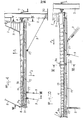
- Fig. 4 is a side elevation, on a larger scale, of a composite winding boom according to the invention.
- Fig. 5 is a transverse view, partly in section, taken on a larger scale substantially along the line V-V of FIG. 4.
- Fig. 6 is a partial elevation illustrating an alternative embodiment of one of the constituent elements of the composite winding boom.
- Fig. 7 is a sectional elevation showing, on a larger scale, another detail of embodiment of the composite winding boom.
- Fig. 8 is a cross section taken, on a larger scale, along the line VIII-VIII of FIG. 4.
- Fig. 9 is a cross section similar to FIG. 8 but showing, on a smaller scale, an alternative embodiment.
- Fig. 10 is an elevation, similar to FIG. 4, but illustrating a development of the invention.
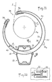
- Fig. It is a cross section taken, substantially, along the line XI-XI of FIG. 10.
- Fig. 12 is a cross section taken, on a larger scale, along the line XII-XII of FIG. He.
- FIG. 13 and 14 are schematic views showing two particular phases of implementation of the realization of the object of the invention according to FIG. 10.
- Fig. 15 is a diagram illustrating certain advantages of implementing the object of the invention.
- FIGS. 16 and 17 are schematic transverse views, similar to FIGS. 13 and 14 showing by comparison two other particular states of implementation of the subject of the invention.
- Fig. 18 is a schematic top view illustrating an alternative embodiment of one of the constituent elements of the object of the invention.
- Fig. 4 shows a winding boom 3a mounted, as recalled by the prior art illustrated in FIG. 2, on a mast 2 by its front end, by means of a gimbal 4 associated with a mechanism 7 for driving in rotation.
- the boom 3a is carried, at its rear end, by a bearing of the collar 8 suspended from the swing 5.
- the boom 3a is used for the establishment, the adjustment and the winding of a sail 1 shown in its fully rolled state, showing a helical winding formed by the fall 11 of the sail 1.
- the composite winding terminal according to the invention comprises, in addition to the boom 3a described above, a beam 12 in tubular box which is suspended by its two ends.
- the beam 12 extends at a distance and under the winding boom 3a, reserving, relative to the latter, an interval 13 sufficient to allow the complete winding of the sail 1 on the boom 3a.
- the suspension of the beam 12 is provided at the front, for example, by means of a stirrup 14 (fig. 5) which is mounted in a groove 15 presented by the half-shaft of the gimbal or of the mullet .
- the stirrup 14 is associated with a plate 16 through which passes a fixing member 17 cooperating with the corresponding end of the beam 12.
- FIG. 6 An alternative embodiment is illustrated in FIG. 6 according to which the suspension of the front end of the beam 12 is ensured by a ring or a shackle 18 engaged in two eyes 19 and 20, respectively carried by the mast 2 and by the corresponding end of the beam 12.
- the tubular box beam 12 is suspended, by its rear end (fig. 7) on the collar 8 which comprises an extension 20 extending downwards, traversed by a fixing member 21 engaged in the corresponding end of the beam 12.
- the suspension means described above make it possible to maintain the beam 12 under the boom 3, whatever the position occupied by the latter, both in the vertical plane and in horizontal offset.
- the beam 12 must have a sufficient moment of inertia so that it can withstand, without excessive deflection, the tensile forces F 2 exerted by the verges. To achieve this result while limiting both its weight and its vertical dimensions, the beam 12 is produced according to the invention so that its cross section is defined (FIG. 8) by two trapezoids joined by their large fictitious bases and thus has two thick bases 22 and 23 connected by two thin lateral walls 24.
- This shape was chosen to have a maximum vertical moment of inertia Iv while retaining a transverse moment of inertia It sufficient to avoid twisting of the beam stressed by forces which in practice are not always oriented in the same plane due to roll, pitch, gusts, swerves, etc.
- the transverse moment is chosen not to be less than 1/6 of the vertical moment and, preferably, the ratio E is chosen equal to 3.5.
- the beam 12 advantageously also includes an internal molding 25 projecting from the internal face of the lower thick base 23 and extends, after suspension under the boom 3a, so that its thick base 22 is located opposite and substantially parallel to the boom.
- This molding 25 allows easy drilling as well as the tapping of holes 26 of transverse direction for mounting traction eyes 27.
- the beam 12 may also include a molding 28 projecting from the internal face of the upper thick base 22.
- This molding 28 may have a longitudinal channel 29 at the ends of which it is easy to execute tappings for mounting the members 17 and 21 then constituted by screws as shown in FIGS. 7 and 8.
- the beam 12 has a base 22 devoid of the molding 28.
- the suspension of the beam can be ensured by providing at each end a plug 30 having an internal molding 30a for execution threads for receiving screws 17 and 21 (fig. 9).
- a development of the invention illustrated by fig. 10 and 11, consists in practicing, in the side walls 24, windows 33 occupying a median transverse plane perpendicular to the axis of the beam 12.
- the windows 33 are made to allow the free engagement of an open ring 34 which can be put on boom 3a, reserving with it a gap 35 compatible with the maximum thickness of complete winding of sail 1.
- the ring 34 is made so that, in the absence of stress applied to the boom 3a and to the beam 12, it is placed substantially coaxially with the boom, without having local contact with the periphery of the latter .
- the ring 34 can be produced in several different ways, in the form of a crescent, from a tubular piece or, again, from a profile, for example in "H" shape, as illustrated in FIG. 12.
- the core 36 connects two wings 37 which extend substantially parallel to the periphery of the winding boom 3a.
- the end portions of the ring 34 define between them a slot 38 and are provided with two removable pads 39 whose function appears in the following.
- the adaptation of the ring 34 through the windows 33 is completed by the interposition of an elastic member 40 placed under tensile tension between the ring 34 and the beam 12.
- the elastic member 40 biases the ring in the direction of the arrow f I (fig. 11), in relative angular displacement, to bring the slot 38 in alignment with a plane tangent to the boom 3a substantially vertical.
- This stable reference position is, for example, determined by a stop 41 carried by the ring 34 to cooperate with the corresponding lateral face 24 of the beam 12.
- the ring 34 is of preferably lined with a coating of a material with a low coefficient of friction, such as polyamide, epoxy, polytetrafluoroethylene.
- the ring 34 occupies the position according to FIG. 11, without peripheral contact with the boom and the sail, given that no upward tensile stress is imposed on the boom 3a and that no downward tensile stress is applied to the beam 12.
- the mechanism 7 When it is necessary to unroll the sail 1, the mechanism 7 is controlled to rotate the boom 3a in the direction of the arrow f 2 .
- the part of the fall 11 progressively unwound moves in the direction of the arrow f 3 , from the position according to FIG. 11 and can freely engage in the slot 38 which occupies, by the action of the spring 40, the corresponding tangent plane.
- the sail can thus be easily unrolled or rolled up, without risk of jamming or tearing.
- the structural connection between the beam 12 and the boom 3a is established by means of the ring and, more particularly, of at least one of the pads 39 which makes it possible to distribute the application pressure and thus avoid the deterioration of the sail, still possibly partially rolled.
- Figs. 13 and 14 illustrate a use case corresponding to a complete unfolding of the sail.
- the sail normally occupies the vertical median plane of the boom at the exit from the groove of the latter and, consequently, biases the ring 34 in angular pivoting against the elastic member 40 to maintain the slot 38 in the plane of the sail 1.
- Figs. 16 and 17 show the same use case with the sail 1 partially rolled on the boom and the ring 34 placed in its stable position by the action of the spring 40.
- Fig. 18 illustrates an alternative embodiment according to which the ring 34 is mounted free to pivot angularly relative to the beam 12, without being connected to the latter by the elastic member 40.
- one of the pads 39 to carry an engagement ramp 42, shaped of helical segment, extending forwards over an axial length greater than the pitch of helical winding of the chute 11.
- the ramp 42 is carried by the pad 39 which is the first encountered by the sail 1 in the direction of winding imposed on the boom 3a by the mechanism 7.
- the ring 34 then comprises two stops 41, 41a (fig. 11) limiting the amplitude of angular displacement relative to the beam 12.
Landscapes
- Engineering & Computer Science (AREA)
- Life Sciences & Earth Sciences (AREA)
- Sustainable Development (AREA)
- Sustainable Energy (AREA)
- Chemical & Material Sciences (AREA)
- Combustion & Propulsion (AREA)
- Mechanical Engineering (AREA)
- Ocean & Marine Engineering (AREA)
- Jib Cranes (AREA)
Applications Claiming Priority (2)
| Application Number | Priority Date | Filing Date | Title |
|---|---|---|---|
| FR8511044 | 1985-07-16 | ||
| FR8511044A FR2584994B1 (fr) | 1985-07-16 | 1985-07-16 | Bome enrouleuse composite pour l'enroulement d'une voile de bateau |
Publications (1)
| Publication Number | Publication Date |
|---|---|
| EP0209475A1 true EP0209475A1 (de) | 1987-01-21 |
Family
ID=9321437
Family Applications (1)
| Application Number | Title | Priority Date | Filing Date |
|---|---|---|---|
| EP86420190A Withdrawn EP0209475A1 (de) | 1985-07-16 | 1986-07-15 | Mehrfachrollbaum zum Aufwickeln eines Bootsegels |
Country Status (3)
| Country | Link |
|---|---|
| EP (1) | EP0209475A1 (de) |
| AU (1) | AU6020686A (de) |
| FR (1) | FR2584994B1 (de) |
Cited By (1)
| Publication number | Priority date | Publication date | Assignee | Title |
|---|---|---|---|---|
| EP3466258A1 (de) * | 2017-10-04 | 2019-04-10 | Deere & Company | System von integrierten durchgängen in einem kohlefaserausleger und verfahren dafür |
Families Citing this family (2)
| Publication number | Priority date | Publication date | Assignee | Title |
|---|---|---|---|---|
| FR2586997B1 (fr) * | 1985-09-11 | 1990-10-19 | Plastimo | Dispositif d'enroulement d'une voile d'un navire sur une bome |
| FR3123311B1 (fr) * | 2021-05-28 | 2024-01-12 | Sparcraft | Système de gréement d’une voile d’un voilier et voilier comprenant un tel système de gréement |
Citations (3)
| Publication number | Priority date | Publication date | Assignee | Title |
|---|---|---|---|---|
| GB1308588A (en) * | 1972-01-04 | 1973-02-21 | Randell Clark M | Reefing claw and reefing assemblies |
| EP0078230A1 (de) * | 1981-10-23 | 1983-05-04 | LEISYSTEM Société anonyme | Einrichtung zum Aufrollen und Aufbewahren von Segeln |
| US4449468A (en) * | 1983-05-19 | 1984-05-22 | Schulz Marine Systems, Inc. | Adjustable roller furling spar |
-
1985
- 1985-07-16 FR FR8511044A patent/FR2584994B1/fr not_active Expired
-
1986
- 1986-07-15 EP EP86420190A patent/EP0209475A1/de not_active Withdrawn
- 1986-07-16 AU AU60206/86A patent/AU6020686A/en not_active Abandoned
Patent Citations (3)
| Publication number | Priority date | Publication date | Assignee | Title |
|---|---|---|---|---|
| GB1308588A (en) * | 1972-01-04 | 1973-02-21 | Randell Clark M | Reefing claw and reefing assemblies |
| EP0078230A1 (de) * | 1981-10-23 | 1983-05-04 | LEISYSTEM Société anonyme | Einrichtung zum Aufrollen und Aufbewahren von Segeln |
| US4449468A (en) * | 1983-05-19 | 1984-05-22 | Schulz Marine Systems, Inc. | Adjustable roller furling spar |
Cited By (4)
| Publication number | Priority date | Publication date | Assignee | Title |
|---|---|---|---|---|
| EP3466258A1 (de) * | 2017-10-04 | 2019-04-10 | Deere & Company | System von integrierten durchgängen in einem kohlefaserausleger und verfahren dafür |
| US10806105B2 (en) | 2017-10-04 | 2020-10-20 | Deere & Company | System of integrated passageways in a carbon fiber boom and method thereof |
| EP3871500A1 (de) * | 2017-10-04 | 2021-09-01 | Deere & Company | System von integrierten durchgängen in einem kohlefaserausleger und verfahren dafür |
| US11903349B2 (en) | 2017-10-04 | 2024-02-20 | Deere & Company | System of integrated passageways in a carbon fiber boom and method thereof |
Also Published As
| Publication number | Publication date |
|---|---|
| FR2584994A1 (fr) | 1987-01-23 |
| FR2584994B1 (fr) | 1988-02-19 |
| AU6020686A (en) | 1987-01-22 |
Similar Documents
| Publication | Publication Date | Title |
|---|---|---|
| EP0008560B1 (de) | Vorsegelroller mit Reffeinrichtung | |
| EP0078230B1 (de) | Einrichtung zum Aufrollen und Aufbewahren von Segeln | |
| EP0434819B1 (de) | Hebe- und aufrichtanker, insbesondere für betonplatten | |
| CA2498729C (fr) | Aile a diedre negatif de traction d'une charge | |
| WO2021148734A1 (fr) | Dispositif cambreur pour voile profilee | |
| EP0011582A1 (de) | Verbesserung an Systemen zum Aufrollen eines Segels | |
| EP0209475A1 (de) | Mehrfachrollbaum zum Aufwickeln eines Bootsegels | |
| WO2009136113A1 (fr) | Ecran de projection équipé de moyens d'exercice de forces de traction verticales et horizontales | |
| FR2886332A1 (fr) | Dispositif d'ecran muni de rails lateraux | |
| EP0330547A1 (de) | Schlingentraggurt | |
| CA1265958A (fr) | Greement, notamment pour planche a voile | |
| FR2492764A1 (fr) | Greement pour planche a voile | |
| EP0141766B1 (de) | Sicherungseinrichtung zum Einhaken des Segelkopfes an der Mastspitze | |
| EP1500755A1 (de) | Anker ausgerüstet mit mindestens einem Dämpfungselement und Ankervorrichtung mit solchen Ankern | |
| EP0325074B1 (de) | Rollsegeleinrichtung mit parallel zum Mast angeordnetem Segelroller | |
| EP0115977B1 (de) | Aufwickelrohr für ein Segel und Vorrichtung zum Aufwickeln von Segeln versehen mit solch einem Rohr | |
| EP0052044A1 (de) | Tauklemmer | |
| EP0225233A1 (de) | Auf einem Mast mit Liekführung montierte Befestigungs- und Führungsvorrichtung für ein Segel mit Liek | |
| EP0310529A1 (de) | Automatische Arretierungsvorrichtung im hochgezogenen Stand eines Segels auf einem Segelbootmast | |
| EP1213220B1 (de) | Führungsvorrichtung für ein Segel | |
| FR2562145A1 (fr) | Dispositif pour le maintien en place d'un rouleau de store et comprenant une butee mobile | |
| FR2577517A1 (fr) | Dispositif pour maitriser la forme des bords d'attaque a fleche positive des voilures de planeurs ultra-legers | |
| FR2645112A1 (fr) | Dispositif de manoeuvre d'une voile epaisse sur un bateau muni d'un mat | |
| WO2023139264A1 (fr) | Mât haubané par un hauban écarté transversalement du mât par une barre de flèche | |
| FR3123311A1 (fr) | Système de gréement d’une voile d’un voilier et voilier comprenant un tel système de gréement |
Legal Events
| Date | Code | Title | Description |
|---|---|---|---|
| PUAI | Public reference made under article 153(3) epc to a published international application that has entered the european phase |
Free format text: ORIGINAL CODE: 0009012 |
|
| AK | Designated contracting states |
Kind code of ref document: A1 Designated state(s): DE GB IT SE |
|
| 17P | Request for examination filed |
Effective date: 19870206 |
|
| 17Q | First examination report despatched |
Effective date: 19871111 |
|
| 18D | Application deemed to be withdrawn |
Effective date: 19880624 |
|
| D18D | Application deemed to be withdrawn (deleted) | ||
| STAA | Information on the status of an ep patent application or granted ep patent |
Free format text: STATUS: THE APPLICATION IS DEEMED TO BE WITHDRAWN |
|
| R18D | Application deemed to be withdrawn (corrected) |
Effective date: 19910201 |
|
| RIN1 | Information on inventor provided before grant (corrected) |
Inventor name: BERNARD, BERNARD |