EP0212570A2 - Rollkolbenverdichter - Google Patents
Rollkolbenverdichter Download PDFInfo
- Publication number
- EP0212570A2 EP0212570A2 EP86111223A EP86111223A EP0212570A2 EP 0212570 A2 EP0212570 A2 EP 0212570A2 EP 86111223 A EP86111223 A EP 86111223A EP 86111223 A EP86111223 A EP 86111223A EP 0212570 A2 EP0212570 A2 EP 0212570A2
- Authority
- EP
- European Patent Office
- Prior art keywords
- compressor according
- piston compressor
- shell
- rotary piston
- ring
- Prior art date
- Legal status (The legal status is an assumption and is not a legal conclusion. Google has not performed a legal analysis and makes no representation as to the accuracy of the status listed.)
- Granted
Links
Images

Classifications
-
- F—MECHANICAL ENGINEERING; LIGHTING; HEATING; WEAPONS; BLASTING
- F04—POSITIVE - DISPLACEMENT MACHINES FOR LIQUIDS; PUMPS FOR LIQUIDS OR ELASTIC FLUIDS
- F04C—ROTARY-PISTON, OR OSCILLATING-PISTON, POSITIVE-DISPLACEMENT MACHINES FOR LIQUIDS; ROTARY-PISTON, OR OSCILLATING-PISTON, POSITIVE-DISPLACEMENT PUMPS
- F04C15/00—Component parts, details or accessories of machines, pumps or pumping installations, not provided for in groups F04C2/00 - F04C14/00
-
- F—MECHANICAL ENGINEERING; LIGHTING; HEATING; WEAPONS; BLASTING
- F04—POSITIVE - DISPLACEMENT MACHINES FOR LIQUIDS; PUMPS FOR LIQUIDS OR ELASTIC FLUIDS
- F04C—ROTARY-PISTON, OR OSCILLATING-PISTON, POSITIVE-DISPLACEMENT MACHINES FOR LIQUIDS; ROTARY-PISTON, OR OSCILLATING-PISTON, POSITIVE-DISPLACEMENT PUMPS
- F04C29/00—Component parts, details or accessories of pumps or pumping installations, not provided for in groups F04C18/00 - F04C28/00
- F04C29/12—Arrangements for admission or discharge of the working fluid, e.g. constructional features of the inlet or outlet
- F04C29/124—Arrangements for admission or discharge of the working fluid, e.g. constructional features of the inlet or outlet with inlet and outlet valves specially adapted for rotary or oscillating piston pumps
-
- F—MECHANICAL ENGINEERING; LIGHTING; HEATING; WEAPONS; BLASTING
- F01—MACHINES OR ENGINES IN GENERAL; ENGINE PLANTS IN GENERAL; STEAM ENGINES
- F01C—ROTARY-PISTON OR OSCILLATING-PISTON MACHINES OR ENGINES
- F01C21/00—Component parts, details or accessories not provided for in groups F01C1/00 - F01C20/00
- F01C21/08—Rotary pistons
- F01C21/0809—Construction of vanes or vane holders
- F01C21/0818—Vane tracking; control therefor
- F01C21/0827—Vane tracking; control therefor by mechanical means
-
- F—MECHANICAL ENGINEERING; LIGHTING; HEATING; WEAPONS; BLASTING
- F04—POSITIVE - DISPLACEMENT MACHINES FOR LIQUIDS; PUMPS FOR LIQUIDS OR ELASTIC FLUIDS
- F04C—ROTARY-PISTON, OR OSCILLATING-PISTON, POSITIVE-DISPLACEMENT MACHINES FOR LIQUIDS; ROTARY-PISTON, OR OSCILLATING-PISTON, POSITIVE-DISPLACEMENT PUMPS
- F04C18/00—Rotary-piston pumps specially adapted for elastic fluids
- F04C18/30—Rotary-piston pumps specially adapted for elastic fluids having the characteristics covered by two or more of groups F04C18/02, F04C18/08, F04C18/22, F04C18/24, F04C18/48, or having the characteristics covered by one of these groups together with some other type of movement between co-operating members
- F04C18/34—Rotary-piston pumps specially adapted for elastic fluids having the characteristics covered by two or more of groups F04C18/02, F04C18/08, F04C18/22, F04C18/24, F04C18/48, or having the characteristics covered by one of these groups together with some other type of movement between co-operating members having the movement defined in group F04C18/08 or F04C18/22 and relative reciprocation between the co-operating members
- F04C18/356—Rotary-piston pumps specially adapted for elastic fluids having the characteristics covered by two or more of groups F04C18/02, F04C18/08, F04C18/22, F04C18/24, F04C18/48, or having the characteristics covered by one of these groups together with some other type of movement between co-operating members having the movement defined in group F04C18/08 or F04C18/22 and relative reciprocation between the co-operating members with vanes reciprocating with respect to the outer member
- F04C18/3562—Rotary-piston pumps specially adapted for elastic fluids having the characteristics covered by two or more of groups F04C18/02, F04C18/08, F04C18/22, F04C18/24, F04C18/48, or having the characteristics covered by one of these groups together with some other type of movement between co-operating members having the movement defined in group F04C18/08 or F04C18/22 and relative reciprocation between the co-operating members with vanes reciprocating with respect to the outer member the inner and outer member being in contact along one line or continuous surfaces substantially parallel to the axis of rotation
- F04C18/3564—Rotary-piston pumps specially adapted for elastic fluids having the characteristics covered by two or more of groups F04C18/02, F04C18/08, F04C18/22, F04C18/24, F04C18/48, or having the characteristics covered by one of these groups together with some other type of movement between co-operating members having the movement defined in group F04C18/08 or F04C18/22 and relative reciprocation between the co-operating members with vanes reciprocating with respect to the outer member the inner and outer member being in contact along one line or continuous surfaces substantially parallel to the axis of rotation the surfaces of the inner and outer member, forming the working space, being surfaces of revolution
-
- F—MECHANICAL ENGINEERING; LIGHTING; HEATING; WEAPONS; BLASTING
- F04—POSITIVE - DISPLACEMENT MACHINES FOR LIQUIDS; PUMPS FOR LIQUIDS OR ELASTIC FLUIDS
- F04C—ROTARY-PISTON, OR OSCILLATING-PISTON, POSITIVE-DISPLACEMENT MACHINES FOR LIQUIDS; ROTARY-PISTON, OR OSCILLATING-PISTON, POSITIVE-DISPLACEMENT PUMPS
- F04C28/00—Control of, monitoring of, or safety arrangements for, pumps or pumping installations specially adapted for elastic fluids
- F04C28/10—Control of, monitoring of, or safety arrangements for, pumps or pumping installations specially adapted for elastic fluids characterised by changing the positions of the inlet or outlet openings with respect to the working chamber
- F04C28/12—Control of, monitoring of, or safety arrangements for, pumps or pumping installations specially adapted for elastic fluids characterised by changing the positions of the inlet or outlet openings with respect to the working chamber using sliding valves
- F04C28/125—Control of, monitoring of, or safety arrangements for, pumps or pumping installations specially adapted for elastic fluids characterised by changing the positions of the inlet or outlet openings with respect to the working chamber using sliding valves with sliding valves controlled by the use of fluid other than the working fluid
-
- F—MECHANICAL ENGINEERING; LIGHTING; HEATING; WEAPONS; BLASTING
- F04—POSITIVE - DISPLACEMENT MACHINES FOR LIQUIDS; PUMPS FOR LIQUIDS OR ELASTIC FLUIDS
- F04C—ROTARY-PISTON, OR OSCILLATING-PISTON, POSITIVE-DISPLACEMENT MACHINES FOR LIQUIDS; ROTARY-PISTON, OR OSCILLATING-PISTON, POSITIVE-DISPLACEMENT PUMPS
- F04C28/00—Control of, monitoring of, or safety arrangements for, pumps or pumping installations specially adapted for elastic fluids
- F04C28/10—Control of, monitoring of, or safety arrangements for, pumps or pumping installations specially adapted for elastic fluids characterised by changing the positions of the inlet or outlet openings with respect to the working chamber
- F04C28/14—Control of, monitoring of, or safety arrangements for, pumps or pumping installations specially adapted for elastic fluids characterised by changing the positions of the inlet or outlet openings with respect to the working chamber using rotating valves
-
- F—MECHANICAL ENGINEERING; LIGHTING; HEATING; WEAPONS; BLASTING
- F04—POSITIVE - DISPLACEMENT MACHINES FOR LIQUIDS; PUMPS FOR LIQUIDS OR ELASTIC FLUIDS
- F04C—ROTARY-PISTON, OR OSCILLATING-PISTON, POSITIVE-DISPLACEMENT MACHINES FOR LIQUIDS; ROTARY-PISTON, OR OSCILLATING-PISTON, POSITIVE-DISPLACEMENT PUMPS
- F04C29/00—Component parts, details or accessories of pumps or pumping installations, not provided for in groups F04C18/00 - F04C28/00
- F04C29/0042—Driving elements, brakes, couplings, transmissions specially adapted for pumps
- F04C29/005—Means for transmitting movement from the prime mover to driven parts of the pump, e.g. clutches, couplings, transmissions
- F04C29/0057—Means for transmitting movement from the prime mover to driven parts of the pump, e.g. clutches, couplings, transmissions for eccentric movement
Definitions
- the invention relates to a rotary piston compressor with a cylinder in which a thin-walled, radially resilient piston with a circular cross section is moved eccentrically with a radial support from a drive shaft, the eccentricity being greater than half the difference in the diameter of the cylinder and the piston.
- the support comprises a rotationally symmetrical, thin-walled shell made of permanently elastic material, in particular stainless steel, one end of which is connected to the piston and the other end of which is held by an externally circular body on which the drive shaft engages.
- the invention creates a support that is flexible in the radial direction, so-called elastic bedding, which, despite its local flexibility, enables a large force transmission overall. Compared to the Known people can significantly reduce the number of rolling bearings required. In addition, there is the advantage of an even distribution of the radial force transmission from the pressure shell to the rolling piston.
- the externally circular body which ensures the "normal shape" of the shell desired for the contact pressure, can be a radially inwardly extending collar of the shell, so that a one-piece component is present. But you can also connect several parts that are favorable in terms of production technology.
- the shell is advantageously a hollow straight cylinder or cone with an opening angle of less than 20 ° because such shapes are easy to manufacture.
- other shapes are also conceivable that meet special requirements.
- the shell can also have a U-shaped cross section in order to enable the transverse force to be transmitted to a roller bearing without bending moment.
- the cup can be connected to the piston by a ring with lubricating properties. This sets a distance between the piston and the bowl, which allows independent deformation over a wide range. At the same time, the lubricating property of the ring reduces wear at the point of power transmission from the shell to the piston.
- a plastic ring, a ring made of carbon or graphite or a sintered metal ring can be used as the ring with lubricating properties.
- the ring can protrude beyond the free end of the shell, so that it runs along the end wall of the cylinder as a sealing edge.
- the piston and / or the shell can be provided at its free end with a recess and / or an elevation to which the ring is attached.
- the ring can also advantageously be composed of two parts that are resiliently movable relative to one another in order to achieve a certain contact pressure with which the part that is in the axial direction lies against the end wall of the cylinder as a piston ring.
- a particularly advantageous embodiment of the invention consists in that two shells with opposite free ends are combined by a common holding body. It has the advantage of a symmetrical introduction of force with which undesired bending moments can be avoided.
- the free ends should be about one and four fifths of the axial length of the piston.
- An eccentric bushing can be rotatably arranged between the collar and the drive shaft.
- the eccentricity can thus be adjusted precisely so that the manufacturing tolerances can be rough. It is also possible to compensate for wear that could occur during extended operation.
- the shell can advantageously have recesses which allow a cooling air flow to the inside of the piston.
- the recesses are preferably round, in particular circular. Their clear width should not exceed one tenth of the diameter of the shell in order not to impair the desired uniform elasticity.
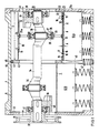
- the rotary piston compressor according to FIG. 1 is provided for charging automotive engines, in particular diesel engines. It has an aluminum housing 1, which forms the cylinder 2 for a rolling piston 3 with two piston parts 4 and 5 offset from one another. The piston parts 4 and 5 are of the same design.
- the cylinder 2 has an inner diameter of 166 mm.
- Each piston part 4, 5 comprises a cylindrical tube 8 made of work hardened stainless steel with a wall thickness of 1.2 mm and a diameter of 145 mm.
- a support in the form of a rotationally symmetrical thin-walled shell 9 also a cylindrical tube section 10 with a wall thickness of 0.3 mm made of the same material.
- the pipe section 10 has a diameter smaller by a distance A than the pipe 8.
- the distance A is, for example, 2 mm. It is set by two-part symmetrical plastic rings 12 and 13, which sit at the free ends 11 of the shell 9.
- the free ends 11, which transmit the supporting force to the piston parts 4, 5, are symmetrical about these at about 20 and 80% of their length L.
- the rings 12, 13 consist of fiber-reinforced plastic and have the cross section shown in FIG. 1. It forms a spacer 15, which lies directly between the shell 9 and the tube 8, and a slotted area 16, in the slot 17 of which a metal spring clip 18 is inserted. With the spring clip 18, an extension 19 extending beyond the tube 8 is placed under axial spring pressure, which, as a piston ring, bears against the end wall 21 of the cylinder 2 with a sealing surface 20. There, the aluminum end wall 21a of the housing 1 is armored with wear-resistant steel rings 22.
- an externally circular wheel body 25 is inserted, which e.g. made of aluminum.
- the wheel body 25 can be glued to the shell 9 in order to obtain a connection that is fixed in the axial direction. However, it can also simply slide against the inside of the shell 9 without play or with little play.
- the wheel body 25 can be provided on the outer circumference with a hard or soft wear protection layer, or else can have an annular wear-resistant intermediate ring 25A made of coated steel or of fiber-reinforced plastic.
- the shell 9 can also be locally reinforced at the force transmission point, for example to a wall thickness of 2 mm.
- An encapsulated ball bearing 26 with a snap ring 27 is fastened in a recess 28 in the wheel body 25.
- the ball bearing 26 sits on a cranked part 30 of a drive shaft 31 made of steel, which carries a V-belt pulley 32 outside the housing 1.
- the drive shaft 31 comprises a central straight shaft piece 34, that connects the cranked shaft part 30 to a shaft part 35 which is symmetrical to it and which is oppositely offset, ie cranked by 180 °, but otherwise of the same design.
- the eccentricity is 10 mm.
- On this shaft piece 35 sits a wheel body which is the same as the wheel body 25 and which carries a further shell 9 in the form of a tube piece 10 for supporting the rolling piston part 5, as is not shown further.
- Fig. 1 shows that the drive shaft 31 is supported at both ends with ball bearings 38 in the end walls 21 of the housing 1.
- two balance weights 39 and 40 are fastened on the drive shaft 31, with which the mass moments on the drive shaft 31 caused by the different transverse forces are compensated.
- the counterweights 39, 40 have bevelled end faces in order to produce a propeller effect with which a cooling air flow is guided in the direction of the arrows 41 through the cylinder 2 and the interior of the piston parts 4, 5.
- a partition 42 is inserted into the cylinder 2 between the two rolling piston parts 4 and 5.
- the partition 42 is made of steel. It has a groove 43 on its circumference with parallel-flanked walls, into which a snap ring 44 is inserted.
- the snap ring 44 engages in a groove 45 in the wall of the cylinder 2. This has the advantage that the cylinder 2 before inserting the partition 42 in one operation for the two halves assigned to the piston parts 4 and 5 can be processed.
- the snap ring 44 is secured with a flat bar 46, which is pressed from one side under the action of a spring 47 into a recess.
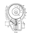
- FIG. 2 shows a separating slide 52 which is guided in the housing 1 and separates the suction chamber 54 connected to an intake connection 53 from the pressure chamber 55, which is connected to the pressure connection 57 of the rotary piston compressor via a group of reed valves 56. Cooling fins 1a improve the heat dissipation from the housing 1, especially in the area of the pressure chamber 55.
- a steel strip 52a can be used, which runs through the entire housing 1 in length.
- the wear of the separating slide 52 on the rolling piston parts 4, 5, in turn, can be reduced by a rotatable sliding shoe 52b.
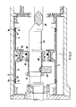
- two shells 9 'with oppositely directed free ends 11' are combined to form a symmetrical component 58 which is made in one piece with a radially inwardly extending collar 25 ', for example as a turned part.
- the ball bearing 26 ' is fastened with an eccentric bush 60 on the drive shaft 31', which can be adjusted with a flange 61.
- the eccentric bush 60 allows an additional Eccentricity of ⁇ 1 mm, an exact setting of the support of the rolling piston 3, with which a conceivable wear can be compensated.
- a counterweight 40 ′ is connected to the eccentric bushing 60 and can be clamped with a nut 64.
- the drive shaft 31 ' here has a lenticular cross section, as indicated at 65.
- Plastic intermediate rings 15 ' are snapped into a 0.4 mm deep groove 8a of the tube 8 which is screwed in from the inside. They are chambered there by the shells 9 'so that they are axially fixed.
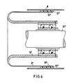
- the shell body 9 ′′ has a U-shaped cross section. Therefore, the free end 11 ′′ of the shell body 9 ′′, which is provided with a ring 12 ′, lies in the same radial plane as the other end 67, which is thickened into a collar and is fastened to the drive shaft 31 ′′ with a double ball bearing.
- FIG. 5 shows that two separating slide parts 52A and 52B of a rotary piston compressor with a tandem arrangement can be controlled via an inherently resilient rocker 70, which is mounted centrally in a rocker bearing 71 and acts on humps 72 and 73 of the two separating slide parts 52A, 52B.
- the rocker 70 can also be under the action of a spring.
- An adjustment facility 74 in the form of an adjustment screw can also be provided, with which the rocker bearing 71, which is provided on a one-armed lever 75, can be adjusted in the direction of the separating slide parts 52A and 52B.
- a stainless steel insert 80 is provided in the aluminum housing 1 of the rotary piston compressor.
- the insert 80 once forms the guide for the slide valve 52 with a groove 81.
- a suction channel is created with a further groove 82.
- a check valve 56 ' is fastened on the opposite side of the insert 80, which can also have several passage cross sections with separate valve members.
- the insert 80 is fixed with a screw 85 which engages in a threaded bore 86.
- the screw 86 can also serve to fix the rocker 70, which is brought with the adjusting device 74 to a suitable distance from the separating slide 52.
Landscapes
- Engineering & Computer Science (AREA)
- Mechanical Engineering (AREA)
- General Engineering & Computer Science (AREA)
- Compressor (AREA)
- Compressors, Vaccum Pumps And Other Relevant Systems (AREA)
- Applications Or Details Of Rotary Compressors (AREA)
- Supercharger (AREA)
Abstract
Description
- Die Erfindung betrifft einen Rollkolbenverdichter mit einem Zylinder, in dem ein dünnwandiger, radial federnder Kolben mit Kreisquerschnitt mit einer radialen Abstützung von einer Antriebswelle exzentrisch bewegt wird, wobei die Exzentrität größer als die halbe Differenz der Durchmesser des Zylinders und des Kolbens ist.
- Bei dem aus der DE-OS 33 43 908 bekannten Rollkolbenverdichter der obengenannten Art wird die zylindrische Kolbenwand von mehreren, an ihrem Umfang verteilten Rollen relativ kleineren Durchmessers geführt. Diese Konstruktion ist fertigungstechnisch aufwendig. Daraus ergibt sich die Aufgabe der Erfindung, eine weniger aufwendige, darüber hinaus auch möglichst verschleißfreie Abstützung zu schaffen, die radiale Verformungen, sogenannte Ovalisierungen, des Kolbens ermöglicht, um durch die dabei entstehende Anpreßkraft eine große innere Dichtigkeit zwischen Zylinder und Kolben zu erhalten.
- Erfindungsgemäß ist vorgesehen, daß die Abstützung eine rotationssymmetrische, dünnwandige Schale aus dauerelastischem Material, insbesondere nichtrostendem Stahl, umfaßt, deren eines Ende mit dem Kolben verbunden ist und deren anderes Ende mit einem außen kreisrunden Körper gehalten ist, an dem die Antriebswelle angreift.
- Mit der Erfindung entsteht eine in radialer Richtung nachgiebige Halterung, sogenannte elastische Bettung, die trotz ihrer lokalen Nachgiebigkeit insgesamt eine große Kraftübertragung ermöglicht. Gegenüber dem Bekannten kann die Zahl der notwendigen Wälzlager ganz wesentlich verringert werden. Zusätzlich ergibt sich der Vorteil einer gleichmäßigen Verteilung der Radialkraftübertragung von der Druckschale auf den Rollkolben.
- Der außen kreisrunde Körper, der die für die Anpreßkraft gewünschte "Normalform" der Schale gewährleistet, kann ein radial nach innen verlaufender Bund der Schale sein, so daß ein einstückiger Bauteil vorliegt. Man kann aber auch mehrere, fertigungstechnisch günstige Teile miteinander verbinden.
- Die Schale ist vorteilhaft ein hohler gerader Zylinder oder ein Konus mit einem Öffnungswinkel von weniger als 20°, weil solche Formen einfach herzustellen sind. Darüber hinaus sind aber auch andere Formen denkbar, die besonderen Ansprüchen genügen. Zum Beispiel kann die Schale auch einen U-förmigen Querschnitt aufweisen, um eine biegemomentfreie Übertragung der Querkraft auf ein Wälzlager zu ermöglichen.
- Die Schale kann mit dem Kolben durch einen Ring mit Schmiereigenschaft verbunden sein. Damit wird ein Abstand zwischen Kolben und Schale eingestellt, der eine in weiten Bereichen unabhängige Verformung zuläßt. Gleichzeitig verringert die Schmiereigenschaft des Ringes den Verschleiß an der Stelle der Kraftübertragung von der Schale auf den Kolben. Als Ring mit Schmiereigenschaft kann ein Kunststoffring, ein Ring aus Kohle oder Graphit oder auch ein Sintermetallring eingesetzt werden.
- Der Ring kann über das freie Ende der Schale hinausragen, so daß er als Dichtkante an der Stirnwand des Zylinders entlang läuft. Dabei kann der Kolben und/oder die Schale an ihrem freien Ende mit einer Vertiefung und/oder einer Erhöhung versehen sein, an der der Ring befestigt ist. Man kann den Ring auch vorteilhaft aus zwei federnd gegeneinander beweglichen Teilen zusammensetzen, um eine gewisse Anpreßkraft zu erreichen, mit der der in axialer Richtung äußere Teil als Kolbenring an der Stirnwand des Zylinders anliegt.
- Eine besonders vorteilhafte Ausführungsform der Erfindung besteht darin, daß zwei Schalen mit entgegengesetzt gerichteten freien Enden durch einen gemeinsamen Haltekörper zusammengefaßt sind. Sie hat den Vorteil einer symmetrischen Krafteinleitung, mit der unerwünschten Biegemomente vermieden werden könne. Die freien Enden sollen dabei bei etwa ein und vier Fünftel der axialen Länge des Kolbens liegen.
- Zwischen dem Bund und der Antriebswelle kann eine Exzenterbüchse verdrehbar angeordnet sein. Damit kann die Exzentrizität genau justiert werden, so daß die Fertigungstoleranzen grob sein können. Es ist ferner möglich damit Verschleiß auszugleichen, der bei längerem Betrieb auftreten könnte.
- Die Schale kann vorteilhaft Ausnehmungen aufweisen, die eine Kühlluftströmung zur Kolbeninnenseite ermöglichen. Vorzugsweise sind die Ausnehmungen rund, insbesondere kreisrund. Ihre lichte Weite sollte höchstens ein Zehntel des Durchmessers der Schale betragen, um die gewünschte gleichmäßige Elastizität nicht zu beeinträchtigen.
- Zur näheren Erläuterung der Erfindung werden anhand der Zeichnung Ausführungsbeispiele beschrieben. Es zeigt:
- Fig. 1 einen Schnitt durch einen Rollkolbenverdichter in Tandembauweise längs der Antriebswelle,
- Fig. 2 einen Querschnitt zur Fig. 1,
- Fig. 3 eine geänderte Ausführungsform in einem Teilschnitt längs der Antriebswelle,
- Fig. 4 eine weitere Ausführungsform in einem Teilschnitt längs der Antriebswelle,
- Fig. 5 eine Einzelheit der Steuerung des Rollkolbenverdichters und
- Fig. 6 einen Einschub für die Steuerung des Rollkolbenverdichters nach der Erfindung.
- Der Rollkolbenverdichter nach Fig. 1 ist zur Aufladung von Kfz-Motoren, insbesondere von Dieselmotoren vorgesehen. Er besitzt ein Aluminiumgehäuse 1, das den Zylinder 2 für einen Rollkolben 3 mit zwei gegeneinander versetzten Kolbenteilen 4 und 5 bildet. Die Kolbenteile 4 und 5 sind gleich ausgebildet. Der Zylinder 2 hat einen Innendurchmesser von 166 mm.
- Jeder Kolbenteil 4, 5 umfaßt ein zylindrisches Rohr 8 aus kaltverfestigtem nichtrostendem Stahl mit einer Wandstärke von 1,2 mm und einem Durchmesser von 145 mm. Innerhalb des Rohres 8 sitzt als Abstützung in Form einer rotationssymmetrischen dünnwandigen Schale 9 ein ebenfalls zylindrisches Rohrstück 10 mit einer Wanddicke von 0,3 mm aus dem gleichen Material. Das Rohrstück 10 hat einen um den Abstand A kleineren Druchmessers als das Rohr 8. Der Abstand A beträgt zum Beispiel 2 mm. Er wird durch zweiteilige symmetrische Kunststoffringe 12 und 13 eingestellt, die an den freien Enden 11 der Schale 9 sitzen. Die freien Enden 11, die die Stützkraft auf die Kolbenteile 4, 5 übertragen, liegen symmetrisch zu diesen bei etwa 20 und 80 % von deren Länge L.
- Die Ringe 12, 13 bestehen aus faserverstärktem Kunststoff und haben den aus der Fig. 1 ersicchtlichen Querschnitt. Er bildet ein Distanzstück 15, das unmittelbar zwischen der Schale 9 und dem Rohr 8 liegt, und einen geschlitzten Bereich 16, in dessen Schlitz 17 eine metallische Federklammer 18 eingesetzt ist. Mit der Federklammer 18 ist eine über das Rohr 8 hinausgreifende Verlängerung 19 unter axialen Federdruck gesetzt, die als Kolbenring mit einer Dichtfläche 20 an der Stirnwand 21 des Zylinders 2 anliegt. Dort ist die Aluminium-Stirnwand 21a des Gehäuses 1 mit verschleißbeständigen Stahlringen 22 gepanzert.
- In der Mitte des Rohrstückes 10, die hier das den freien Enden 11 abgekehrte Ende 24 der Schale 9 bildet, ist ein außen kreisrunder Radkörper 25 eingesetzt, der z.B. aus Aluminium besteht. Der Radkörper 25 kann mit der Schale 9 verklebt sein, um eine in axiale Richtung feste Verbindung zu erhalten. Er kann aber auch einfach auf der Innenseite der Schale 9 ohne Spiel oder mit geringem Spiel gleitend anliegen. Der Radkörper 25 kann am Außenumfang mit einer harten oder weichen Verschleißschutzschicht versehen sein, oder aber einen ringförmigen verschleißbeständigen Zwischenring 25A aus beschichtetem Stahl oder aus faserverstärktem Kunststoff aufweisen. Die Schale 9 kann an der Kraftübertragungsstelle auch örtlich verstärkt sein auf zum Beispiel 2 mm Wanddicke.
- In einer Ausnehmung 28 des Radkörpers 25 ist ein gekapseltes Kugellager 26 mit einem Sprengring 27 befestigt. Das Kugellager 26 sitzt auf einem gekröpften Teil 30 einer Antriebswelle 31 aus Stahl, die außerhalb des Gehäuses 1 eine Keilriemenscheibe 32 trägt. Die Antriebswelle 31 umfaßt ein zentrales geradliniges Wellenstück 34, das den gekröpften Wellenteil 30 mit einem symmetrisch dazu liegenden und entgegengesetzt, d.h. um 180° versetzt gekröpften, sonst aber gleich ausgebildeten Wellenteil 35 verbindet. Die Exzentrizität beträgt 10 mm. Auf diesem Wellenstück 35 sitzt ein dem Radkörper 25 gleicher Radkörper, der eine weitere Schale 9 in Form eines Rohrstückes 10 zur Abstützung für den Rollkolbenteil 5 trägt, wie nicht weiter dargestellt ist.
- Die Fig. 1 zeigt, daß die Antriebswelle 31 an ihren beiden Enden mit Kugellagern 38 in den Stirnwänden 21 des Gehäuses 1 gelagert ist. Unmittelbar benachbart zu den Kugellagern 38 sind zwei Ausgleichsgewichte 39 und 40 auf der Antriebswelle 31 befestigt, mit denen die durch die unterschiedlichen Querkräfte entstehenden Massenmomente an der Antriebswelle 31 ausgeglichen werden. Die Ausgleichsgewichte 39, 40 haben abgeschrägte Stirnseiten, um eine Propellerwirkung zu erzeugen, mit der eine Kühlluftströmung in Richtung der Pfeile 41 durch den Zylinder 2 und das Innere der Kolbenteile 4, 5 geführt wird. Durch Ausnehmungen in den Schalen 9 kann diese Kühlluftströmung direkt an die Innenseite des Kolbens 8 geführt werden, sodaß die Verdichtungswärme nach innen ebenso wie nach außen abgeführt wird und auf diese Weise eine Annäherung der Verdichtungs-Polytrope an eine Isotherme bewirkt wird. Dies spart erheblich an mechanischer Antriebsleistung für den Verdichter.
- Zwischen den beiden Rollkolbenteilen 4 und 5 ist eine Trennwand 42 in den Zylinder 2 eingefügt. Die Trennwand 42 besteht aus Stahl. Sie hat an ihrem Umfang eine Nut 43 mit parallelflankigen Wänden, in die ein Sprengring 44 eingesetzt ist. Der Sprengring 44 greift in eine Nut 45 in der Wand des Zylinders 2. Dies hat den Vorteil, daß der Zylinder 2 vor dem Einsetzen der Trennwand 42 in einem Arbeitsgang für die beiden, den Kolbenteilen 4 und 5 zugeordneten Hälften bearbeitet werden kann. Der Sprengring 44 ist mit einem Flachkantstab 46 gesichert, der von einer Seite her unter der Wirkung einer Feder 47 in eine Ausnehmung gedrückt wird.
- In Fig. 2 ist zu sehen, daß der Radkörper 25 mit Ausnehmungen 50 versehen ist, die die Kühlmittelströmung ermöglichen sowie eine Gewichtsersparnis bedeuten und zugleich die beim Anfahren in Bewegung zu setzenden Massen verringert. Ferner zeigt die Fig. 2 einen Trennschieber 52, der in dem Gehäuse 1 geführt ist und den an einen Ansaugstutzen 53 angeschlossenen Saugraum 54 von dem Druckraum 55 trennt, der über eine Gruppe von Zungenventilen 56 mit dem Druckstutzen 57 des Rollkolbenverdichters verbunden ist. Kühlrippen 1a verbessern die Wärmeabfuhr aus dem Gehäuse 1 vor allem im Bereich des Druckraumes 55.
- Um den Verschleiß des aus Kunststoff bestehenden Trennschiebers 52 gegen das Aluminiumgehäuse 1 zu mindern, kann eine stählerne Leiste 52a eingesetzt werden, die in der Länge über das ganze Gehäuse 1 durchläuft. Den Verschleiß des Trennschiebers 52 an den Rollkolbenteilen 4, 5 wiederum kann ein drehbeweglich aufgesteckter Gleitschuh 52b mindern helfen.
- Bei dem Ausführungsbeispiel nach Fig. 3 sind zwei Schalen 9' mit entgegengesetzt gerichteten freien Enden 11' zu einem symmetrischen Bauteil 58 zusammengefaßt, der mit einem radial nach innen verlaufenden Bund 25' in einem Stück hergestellt ist, zum Beispiel als Drehteil. Hierbei ist das Kugellager 26' mit einer Exzenterbüchse 60 auf der Antriebswelle 31' befestigt, die mit einem Flansch 61 verstellt werden kann. Die Exzenterbüchse 60 gestattet mit einer zusätzlichen Exzentrizität von ± 1 mm eine genaue Einstellung der Abstützung des Rollkolbens 3, mit der auch ein denkbarer Verschleiß ausgeglichen werden kann. Mit der Exzenterbüchse 60 steht ein Gegengewicht 40' in Verbindung, das mit einer Mutter 64 festgeklemmt werden kann. Die Antriebswelle 31' hat hier einen linsenförmigen Querschnitt, wie bei 65 angedeutet ist. Zwischenringe 15' aus Kunststoff sind in eine von innen her eingedrehte 0,4 mm tiefe Nut 8a des Rohres 8 eingeschnappt. Sie werden dort durch die Schalen 9' eingekammert, sodaß sie axial festgelegt sind.
- Bei dem Ausführungsbeispiel nach Fig. 4 hat der Schalenkörper 9'' einen U-förmigen Querschnitt. Deshalb liegt das mit einem Ring 12' versehene freie Ende 11'' des Schalenkörpers 9'' in derselben Radialebene wie das zu einem Bund verdickte andere Ende 67, das mit einem Doppelkugellager auf der Antriebswelle 31'' befestigt ist.
- Die Fig. 5 zeigt, daß zwei Trennschieberteilen 52A und 52B eines Rollkolbenverdichters mit Tandemanordnung über eine in sich federnde Wippe 70 gesteuert werden können, die zentrisch in einem Wippenlager 71 gelagert ist und auf Höcker 72 und 73 der beiden Trennschieberteile 52A, 52B wirkt. Die Wippe 70 kann zusätzlich unter der Wirkung einer Feder stehen. Man kann ferner eine Nachstellmöglichkeit 74 in Form einer Nachstellschraube vorsehen, mit der das Wippenlager 71, das an einem einarmigen Hebel 75 vorgesehen ist, in Richtung auf die Trennschieberteile 52A und 52B verstellt werden kann.
- In Fig. 6 ist dargestellt, daß in dem aus Aluminium bestehenden Gehäuse 1 des Rollkolbenverdichters ein aus nichtrostendem Stahl bestehender Einschub 80 vorgesehen ist. Der Einschub 80 bildet einmal die Führung für den Trennschieber 52 mit einer Nut 81. Ferner ist mit einer weiteren Nut 82 ein Ansaugkanal geschaffen. Schließlich ist auf der gegenüberliegenden Seite des Einschubs 80 ein Rückschlagventil 56' befestigt, das auch mehrere Durchlaßquerschnitte mit getrennten Ventilgliedern haben kann. Der Einschub 80 ist mit einer Schraube 85 festgelegt, die in eine Gewindebohrung 86 greift. Die Schraube 86 kann auch zur Festlegung der Wippe 70 dienen, die mit der Justiereinrichtung 74 auf eine geeignete Distanz gegenüber dem Trennschieber 52 gebracht wird.
- Nicht dargestellt ist die Möglichkeit, die Schale 9 beidseitig in Trompetenform geringfügig konisch (Öffnungswinkel 3° zur Wellenmitte hin) aufzuweiten, zum Beispiel vom Außendurchmesser 138 auf 142 mm, um die Enden 11 im Durchmesser an den Innendurchmesser des Kolbens 3 (142 mm) anzugleichen. Zu diesem Fall entfällt ein Kunststoff-Zwischenring 12, 13. Dafür empfiehlt sich eine verschleißbeständige Panzerung zum Beispiel durch eine Detonationsbeschichtung mit Chromcarbid in einer Cr-Ni-Matrix.
Claims (14)
dadurch gekennzeichnet,
daß die Abstützung eine rotationssymmetrische, dünnwandige Schale (9) aus dauerelastischem Material, insbesondere nichtrostendem Stahl, umfaßt, deren eines Ende (11) mit dem Kolben (3) verbunden ist und deren anderes Ende (24) mit einem außen kreisrunden Körper (25) gehalten ist, an dem die Antriebswelle (31) angreift.
dadurch gekennzeichnet,
daß der Körper ein radial nach innen verlaufender Bund (25') der Schale (9') ist. (Fig. 3)
dadurch gekennzeichnet,
daß die Schale (9) als hohler gerader Zylinder oder Konus mit einem Öffnungswinkel von weniger als 20° ausgebildet ist.
dadurch gekennzeichnet,
daß die Schale (9) mit dem Kolben (3) durch einen Ring (12, 13) mit Schmiereigenschaft verbunden ist.
dadurch gekennzeichnet,
daß der Ring (12, 13) über das freie Ende (11) der Schale (90) hinausragt.
dadurch gekennzeichnet,
daß der Kolben (3) und/oder die Schale (9) mit einer Vertiefung (8a) und/oder Erhöhung versehen ist, an der der Ring (12, 13) befestigt ist.
dadurch gekennzeichnet,
daß der Ring (12, 13) zwei federnd gegeneinander bewegliche Teile (15, 19) umfaßt, von denen der in axialer Richtung äußere Teil (19) als Kolbenring an der Stirnwand (21) des Zylinders (2) anliegt und abdichtet.
dadurch gekennzeichnet,
daß zwei Schalen (9') mit entgegengesetzt gerichteten freien Enden (11') durch einen gemeinsamen Bund (25') zusammengefaßt sind. (Fig. 3)
dadurch gekennzeichnet,
daß die freien Enden (11) bei etwa ein und vier Fünftel der axialen Länge (L) des Kolbens liegen.
dadurch gekennzeichnet,
daß zwischen dem Bund (25') und der Antriebswelle (31') eine Exzenterbüchse (6) verdehbar angeordnet ist. (Fig.3)
dadurch gekennzeichnet,
daß die Schale (9) Ausnehmungen aufweist.
dadurch gekennzeichnet,
daß die Ausnehmungen rund, insbesondere kreisrund sind und eine lichte Weite haben, die höchstens ein Zehntel des Durchmessers der Schale (9) beträgt.
dadurch gekennzeichnet,
daß der außenkreisrunde Körper ein Radkörper (25) mit einer Verschleißschutzschicht (25a) am Außenumfang ist.
dadurch gekennzeichnet,
daß die Schale (9) im Bereich des kreisrunden Körpers (25) verstärkt ist.
Priority Applications (1)
| Application Number | Priority Date | Filing Date | Title |
|---|---|---|---|
| AT86111223T ATE53636T1 (de) | 1985-08-26 | 1986-08-13 | Rollkolbenverdichter. |
Applications Claiming Priority (2)
| Application Number | Priority Date | Filing Date | Title |
|---|---|---|---|
| DE3530436 | 1985-08-26 | ||
| DE19853530436 DE3530436A1 (de) | 1985-08-26 | 1985-08-26 | Rollkolbenverdichter |
Publications (3)
| Publication Number | Publication Date |
|---|---|
| EP0212570A2 true EP0212570A2 (de) | 1987-03-04 |
| EP0212570A3 EP0212570A3 (en) | 1988-08-10 |
| EP0212570B1 EP0212570B1 (de) | 1990-06-13 |
Family
ID=6279372
Family Applications (1)
| Application Number | Title | Priority Date | Filing Date |
|---|---|---|---|
| EP86111223A Expired - Lifetime EP0212570B1 (de) | 1985-08-26 | 1986-08-13 | Rollkolbenverdichter |
Country Status (9)
| Country | Link |
|---|---|
| US (1) | US4743182A (de) |
| EP (1) | EP0212570B1 (de) |
| JP (1) | JPS6251786A (de) |
| KR (1) | KR870002379A (de) |
| AT (1) | ATE53636T1 (de) |
| BR (1) | BR8604041A (de) |
| DD (1) | DD249310A5 (de) |
| DE (2) | DE3530436A1 (de) |
| ZA (1) | ZA866417B (de) |
Cited By (1)
| Publication number | Priority date | Publication date | Assignee | Title |
|---|---|---|---|---|
| EP0240823A3 (en) * | 1986-04-04 | 1988-09-28 | Siemens Aktiengesellschaft | Rolling piston compressor |
Families Citing this family (5)
| Publication number | Priority date | Publication date | Assignee | Title |
|---|---|---|---|---|
| DE3727697A1 (de) * | 1987-03-23 | 1989-03-02 | Siemens Ag | Rollkolbenverdichter |
| DE3823027A1 (de) * | 1988-07-07 | 1990-01-11 | Kurt G Dipl Ing Fickelscher | Maschine mit einem duennwandigen rollkolben |
| US4975031A (en) * | 1989-01-09 | 1990-12-04 | General Electric Company | Rotary compressor with compliant impact surfaces |
| JP5743019B1 (ja) * | 2013-12-13 | 2015-07-01 | ダイキン工業株式会社 | 圧縮機 |
| JP2015158144A (ja) * | 2014-02-21 | 2015-09-03 | 大豊工業株式会社 | ローリングピストンおよびロータリー型流体機械 |
Family Cites Families (9)
| Publication number | Priority date | Publication date | Assignee | Title |
|---|---|---|---|---|
| DE590394C (de) * | 1931-01-30 | 1933-12-30 | Const Mecaniques L Aster Atel | Pumpe mit zylindrischem Gehaeuse |
| US3193192A (en) * | 1962-08-22 | 1965-07-06 | Firewel Company Inc | Internally cooled gas pump |
| SU370367A1 (ru) * | 1971-01-04 | 1973-02-15 | Авторы изобретени витель | Вакуумный пластинчато-статорный насос |
| US3767333A (en) * | 1971-09-03 | 1973-10-23 | B Ashikian | Energy converters with crankpin concentric pistons |
| US3806977A (en) * | 1972-11-06 | 1974-04-30 | C Anderson | Gas supply mechanism for erasing machines |
| US4139336A (en) * | 1977-07-18 | 1979-02-13 | Hopkins Walter M | Expansible chamber apparatus with pairs of cylindrical rollers |
| DE2832568A1 (de) * | 1978-07-25 | 1980-02-07 | Alfmeier Walter Gmbh & Co | Drehkolbenpumpe |
| US4507064A (en) * | 1982-06-01 | 1985-03-26 | Vilter Manufacturing Corporation | Rotary gas compressor having rolling pistons |
| DE3343908A1 (de) * | 1983-12-05 | 1984-06-28 | Kurt G. Ing.(grad.) 6710 Frankenthal Fickelscher | Maschine, insbesondere arbeitsmaschine zum verdichten und foerdern von fluiden aller art |
-
1985
- 1985-08-26 DE DE19853530436 patent/DE3530436A1/de not_active Withdrawn
-
1986
- 1986-08-13 EP EP86111223A patent/EP0212570B1/de not_active Expired - Lifetime
- 1986-08-13 DE DE8686111223T patent/DE3671942D1/de not_active Expired - Lifetime
- 1986-08-13 AT AT86111223T patent/ATE53636T1/de not_active IP Right Cessation
- 1986-08-21 US US06/898,696 patent/US4743182A/en not_active Expired - Fee Related
- 1986-08-22 JP JP61196998A patent/JPS6251786A/ja active Pending
- 1986-08-22 DD DD86293797A patent/DD249310A5/de not_active IP Right Cessation
- 1986-08-25 KR KR1019860007031A patent/KR870002379A/ko not_active Withdrawn
- 1986-08-25 BR BR8604041A patent/BR8604041A/pt unknown
- 1986-08-25 ZA ZA866417A patent/ZA866417B/xx unknown
Cited By (1)
| Publication number | Priority date | Publication date | Assignee | Title |
|---|---|---|---|---|
| EP0240823A3 (en) * | 1986-04-04 | 1988-09-28 | Siemens Aktiengesellschaft | Rolling piston compressor |
Also Published As
| Publication number | Publication date |
|---|---|
| EP0212570A3 (en) | 1988-08-10 |
| DE3671942D1 (de) | 1990-07-19 |
| EP0212570B1 (de) | 1990-06-13 |
| KR870002379A (ko) | 1987-03-31 |
| US4743182A (en) | 1988-05-10 |
| DD249310A5 (de) | 1987-09-02 |
| ATE53636T1 (de) | 1990-06-15 |
| JPS6251786A (ja) | 1987-03-06 |
| ZA866417B (en) | 1987-04-29 |
| BR8604041A (pt) | 1987-06-30 |
| DE3530436A1 (de) | 1987-02-26 |
Similar Documents
| Publication | Publication Date | Title |
|---|---|---|
| DE69605462T2 (de) | Spiralvakuumpumpe | |
| DE2061063C3 (de) | Kraftschlüssige Verbindung eines Antriebskopfs mit einer Kolbenstange | |
| DE2905867C2 (de) | Dichtungsvorrichtung | |
| DE4314892B4 (de) | Kolbenbaugruppe | |
| DE19611004A1 (de) | Taumelscheibenkompressor | |
| WO1997033108A1 (de) | Dichtung für einen ringkolben einer hydraulischen kupplungs-ausrückvorrichtung | |
| EP0147654B1 (de) | Maschine, insbesondere Arbeitsmaschine zum Verdichten und Fördern von Fluiden | |
| DE19544287C2 (de) | Taumelscheibenverdichter | |
| DE69714935T2 (de) | Abgedichtete exzentergetriebene welle für eine verdrängerpumpe | |
| EP0212570B1 (de) | Rollkolbenverdichter | |
| CH661318A5 (de) | Rotationskolbenmaschine. | |
| DE3222982C2 (de) | Drehkolbenzylinder | |
| DE19947677B4 (de) | Axialkolbenverdichter | |
| DE2509536A1 (de) | Kompressor mit einem zu seiner antriebswelle exzentrischen rollkolben | |
| DE2454956A1 (de) | Mehrstufiger hubkolbenkompressor | |
| EP1588051B1 (de) | Kolbenmaschine mit welle und wälzlager | |
| DE10052895B4 (de) | Kompressor | |
| DE4224075A1 (de) | Hydraulisches Antriebs- und Bremssystem | |
| DE4326366A1 (de) | Kompressor der Taumelscheibenbauart | |
| DE3530432A1 (de) | Rollkolbenverdichter | |
| DE10255680B4 (de) | Axialkolbenverdichter, insbesondere CO 2-Verdichter für Fahrzeug-Klimaanlagen mit geteiltem Zylinderkopf | |
| EP0283867B1 (de) | Rollkolbenverdichter | |
| DE10051420A1 (de) | Zylinderblock eines Axialkolbenverdichters mit verlängerter Zylinderlauffläche | |
| DE2313059C3 (de) | ||
| DE102007048741B4 (de) | Hubkolbenmaschine mit Doppelkolben und Exzenteran- oder Exzenterabtrieb |
Legal Events
| Date | Code | Title | Description |
|---|---|---|---|
| PUAI | Public reference made under article 153(3) epc to a published international application that has entered the european phase |
Free format text: ORIGINAL CODE: 0009012 |
|
| AK | Designated contracting states |
Kind code of ref document: A2 Designated state(s): AT CH DE FR GB IT LI SE |
|
| RAP1 | Party data changed (applicant data changed or rights of an application transferred) |
Owner name: SIEMENS AKTIENGESELLSCHAFT |
|
| PUAL | Search report despatched |
Free format text: ORIGINAL CODE: 0009013 |
|
| AK | Designated contracting states |
Kind code of ref document: A3 Designated state(s): AT CH DE FR GB IT LI SE |
|
| 17P | Request for examination filed |
Effective date: 19880830 |
|
| 17Q | First examination report despatched |
Effective date: 19890309 |
|
| GRAA | (expected) grant |
Free format text: ORIGINAL CODE: 0009210 |
|
| AK | Designated contracting states |
Kind code of ref document: B1 Designated state(s): AT CH DE FR GB IT LI SE |
|
| PG25 | Lapsed in a contracting state [announced via postgrant information from national office to epo] |
Ref country code: SE Effective date: 19900613 |
|
| REF | Corresponds to: |
Ref document number: 53636 Country of ref document: AT Date of ref document: 19900615 Kind code of ref document: T |
|
| REF | Corresponds to: |
Ref document number: 3671942 Country of ref document: DE Date of ref document: 19900719 |
|
| ET | Fr: translation filed | ||
| ITF | It: translation for a ep patent filed | ||
| GBT | Gb: translation of ep patent filed (gb section 77(6)(a)/1977) | ||
| PLBE | No opposition filed within time limit |
Free format text: ORIGINAL CODE: 0009261 |
|
| STAA | Information on the status of an ep patent application or granted ep patent |
Free format text: STATUS: NO OPPOSITION FILED WITHIN TIME LIMIT |
|
| 26N | No opposition filed | ||
| PGFP | Annual fee paid to national office [announced via postgrant information from national office to epo] |
Ref country code: GB Payment date: 19910718 Year of fee payment: 6 |
|
| PGFP | Annual fee paid to national office [announced via postgrant information from national office to epo] |
Ref country code: AT Payment date: 19910726 Year of fee payment: 6 |
|
| PGFP | Annual fee paid to national office [announced via postgrant information from national office to epo] |
Ref country code: FR Payment date: 19910823 Year of fee payment: 6 |
|
| ITTA | It: last paid annual fee | ||
| PGFP | Annual fee paid to national office [announced via postgrant information from national office to epo] |
Ref country code: DE Payment date: 19911029 Year of fee payment: 6 |
|
| PGFP | Annual fee paid to national office [announced via postgrant information from national office to epo] |
Ref country code: CH Payment date: 19911122 Year of fee payment: 6 |
|
| PG25 | Lapsed in a contracting state [announced via postgrant information from national office to epo] |
Ref country code: GB Effective date: 19920813 Ref country code: AT Effective date: 19920813 |
|
| PG25 | Lapsed in a contracting state [announced via postgrant information from national office to epo] |
Ref country code: LI Effective date: 19920831 Ref country code: CH Effective date: 19920831 |
|
| GBPC | Gb: european patent ceased through non-payment of renewal fee |
Effective date: 19920813 |
|
| PG25 | Lapsed in a contracting state [announced via postgrant information from national office to epo] |
Ref country code: FR Effective date: 19930430 |
|
| REG | Reference to a national code |
Ref country code: CH Ref legal event code: PL |
|
| PG25 | Lapsed in a contracting state [announced via postgrant information from national office to epo] |
Ref country code: DE Effective date: 19930501 |
|
| REG | Reference to a national code |
Ref country code: FR Ref legal event code: ST |
|
| PG25 | Lapsed in a contracting state [announced via postgrant information from national office to epo] |
Ref country code: IT Free format text: LAPSE BECAUSE OF NON-PAYMENT OF DUE FEES;WARNING: LAPSES OF ITALIAN PATENTS WITH EFFECTIVE DATE BEFORE 2007 MAY HAVE OCCURRED AT ANY TIME BEFORE 2007. THE CORRECT EFFECTIVE DATE MAY BE DIFFERENT FROM THE ONE RECORDED. Effective date: 20050813 |