EP0212661A2 - Current limiter - Google Patents
Current limiter Download PDFInfo
- Publication number
- EP0212661A2 EP0212661A2 EP86111815A EP86111815A EP0212661A2 EP 0212661 A2 EP0212661 A2 EP 0212661A2 EP 86111815 A EP86111815 A EP 86111815A EP 86111815 A EP86111815 A EP 86111815A EP 0212661 A2 EP0212661 A2 EP 0212661A2
- Authority
- EP
- European Patent Office
- Prior art keywords
- current limiter
- rails
- arc
- runner
- current
- Prior art date
- Legal status (The legal status is an assumption and is not a legal conclusion. Google has not performed a legal analysis and makes no representation as to the accuracy of the status listed.)
- Granted
Links
- 239000004020 conductor Substances 0.000 claims abstract description 6
- 239000011810 insulating material Substances 0.000 claims abstract description 5
- 239000007787 solid Substances 0.000 claims abstract description 4
- 238000012546 transfer Methods 0.000 claims description 2
- 230000003014 reinforcing effect Effects 0.000 claims 1
- 238000013461 design Methods 0.000 description 5
- 239000000463 material Substances 0.000 description 3
- RYGMFSIKBFXOCR-UHFFFAOYSA-N Copper Chemical compound [Cu] RYGMFSIKBFXOCR-UHFFFAOYSA-N 0.000 description 2
- 238000010521 absorption reaction Methods 0.000 description 2
- 230000008901 benefit Effects 0.000 description 2
- 239000010949 copper Substances 0.000 description 2
- 229910052802 copper Inorganic materials 0.000 description 2
- 238000003780 insertion Methods 0.000 description 2
- 230000037431 insertion Effects 0.000 description 2
- 238000013508 migration Methods 0.000 description 2
- 230000005012 migration Effects 0.000 description 2
- TWNQGVIAIRXVLR-UHFFFAOYSA-N oxo(oxoalumanyloxy)alumane Chemical compound O=[Al]O[Al]=O TWNQGVIAIRXVLR-UHFFFAOYSA-N 0.000 description 2
- 229910001369 Brass Inorganic materials 0.000 description 1
- 230000009471 action Effects 0.000 description 1
- 238000013459 approach Methods 0.000 description 1
- 239000010951 brass Substances 0.000 description 1
- 238000001816 cooling Methods 0.000 description 1
- 238000011161 development Methods 0.000 description 1
- 230000018109 developmental process Effects 0.000 description 1
- 238000006073 displacement reaction Methods 0.000 description 1
- 239000011521 glass Substances 0.000 description 1
- 238000009413 insulation Methods 0.000 description 1
- 238000004519 manufacturing process Methods 0.000 description 1
- 238000000034 method Methods 0.000 description 1
- 239000010445 mica Substances 0.000 description 1
- 229910052618 mica group Inorganic materials 0.000 description 1
- 230000008569 process Effects 0.000 description 1
- 230000009467 reduction Effects 0.000 description 1
- 230000002787 reinforcement Effects 0.000 description 1
Images


Classifications
-
- H—ELECTRICITY
- H01—ELECTRIC ELEMENTS
- H01H—ELECTRIC SWITCHES; RELAYS; SELECTORS; EMERGENCY PROTECTIVE DEVICES
- H01H9/00—Details of switching devices, not covered by groups H01H1/00 - H01H7/00
- H01H9/30—Means for extinguishing or preventing arc between current-carrying parts
- H01H9/42—Impedances connected with contacts
-
- H—ELECTRICITY
- H01—ELECTRIC ELEMENTS
- H01H—ELECTRIC SWITCHES; RELAYS; SELECTORS; EMERGENCY PROTECTIVE DEVICES
- H01H9/00—Details of switching devices, not covered by groups H01H1/00 - H01H7/00
- H01H9/30—Means for extinguishing or preventing arc between current-carrying parts
- H01H9/44—Means for extinguishing or preventing arc between current-carrying parts using blow-out magnet
-
- H—ELECTRICITY
- H01—ELECTRIC ELEMENTS
- H01H—ELECTRIC SWITCHES; RELAYS; SELECTORS; EMERGENCY PROTECTIVE DEVICES
- H01H9/00—Details of switching devices, not covered by groups H01H1/00 - H01H7/00
- H01H9/30—Means for extinguishing or preventing arc between current-carrying parts
- H01H9/46—Means for extinguishing or preventing arc between current-carrying parts using arcing horns
- H01H9/465—Shunt circuit closed by transferring the arc onto an auxiliary electrode
Definitions
- the invention relates to a current limiter according to the precharacterising part of claim 1.
- the present invention aims to provide a current limiter of the above-mentioned kind, which is designed for intermediate and high voltages and which, at the same time, fulfills the demands for a high energy absorption capacity and sufficient resistance per unit of length of the runner rails.
- the runner rails By making the runner rails of an insulated metallic tape, which is folded and packed together into a solid resistance package, several advantages are obtained. Since the tape is thin in relation to its width and since antiparallel current paths are formed, the inductance will be extremely low, which enables a fast travelling of the arc. By the choice of thickness and width of the tape as well as the length of folding, an arbitrary resistance per unit of length can be easily obtained for a given amount of energy to be absorbed.
- the current limiter according to the invention is primarily intended for the intermediate and high voltage ranges (i. e. voltages exceeding 1 kV), but in principle it may be employed for low voltages as well.
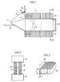
- the current limiter shown in Figures 1 and 2 comprises a contact means 1 with a fixed contact 11 and a contact 12 which is rotatable about an axis.
- the contacts 11 and 12 are each connected to a connection member 15 and 16, respectively, for connecting the current limiter into a circuit.
- the connection between the movable contact 12 and the connection member 16 takes place via a flexible conductor 14.
- each rail is fixedly connected to one of the connection members 15 and 16. At their other end, the rails are fixedly interconnected by means of a rail 23.
- the runner rails 21, 22 are manufactured from an insulated tape 24 ( Figure 3) of electrically conductive material, for example copper, brass or the like, which has been folded and packed into a solid package of rectangular cross-section.
- the thickness t and width b of the tape as well as the length of folding s are chosen in view of the system voltage and the material of the tape so, that a desired resistance per unit of length of the rails is achieved.
- the thickness t of the tape may, for example, lie between 0,1 and 2 mm, the width b between 15 and 100 mm and the length of folding s between 30 and 200 mm.
- these values are stated as examples only and do not at all constitute any limiting minimum or maximum values.
- a resistance of, for example 4 mP-/cm may be suitable, which can be attained by using a copper tape with a thickness of about 0,3 mm, a width of about 20 mm and a length of folding of about 50 mmm.
- the length of the rails may be of the order of magnitude of 1 m.
- the runner rails may, for example, be oriented in such a way that confronting surfaces of the two rails are formed by the curved portions of the tape, as shown in Figure 1. The insulation on these surfaces is then removed at least along the mid-portion of these surfaces so as to form running paths for the foot points of the arc.
- two parallel walls 31,32 of insulating material extend, which form between them a gap 33 for the arc, as will be clear from Figure 2.
- a considerable amount of energy will be transferred from the arc to the wall while at the same time the velocity of the arc is increased.
- material in the walls different inorganic insulating materials, such as mica glass or aluminum oxide, are feasible.
- the good thermal conductivity of aluminum oxide is advantageous in this connection.
- the inwardly-facing surfaces of the walls can be made rough or be enlarged, for example by providing them with grooves or the like. Also certain organic insulating materials, which may possibly give off gas when being heated, may come into question as materials in the walls 31,32.
- the contact means 1 When a short-circuit occurs in the circuit equipped with the current limiter, the contact means 1 is immediately opened by the action of an automatically acting operating device (not shown).
- the arc 4 which is struck between the contacts 11 and 12, is moved under the influence 4 the magnetic field generated by the current, into the gap 33 where the foot points of the arc are rapidly moved along the runner rails 21,22, the resistance of the rails thereby being successively connected into the circuit. Since the tape 24 is thin in relation to the width and forms antiparallel current paths, as shown by arrows in Figure 1, the inductance of the rails 21,22 will be very low, which contributes to a rapid arc travelling.
- the arc 4 approaches the outer ends of the guide rails, which ends are short-circuited by the connecting rail 23 , and extinguishes.
- the total resistance of the runner rails will then be inserted into the circuit, thus achieving a considerable limitation of the short-circuit current and a reduction of the phase displacement between current and voltage.
- the short-circuit current thus limited can then easily be broken by a circuit-breaker arranged in series with the current limiter.
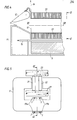
- a magnetic core 5 can be arranged around one of the runner rails, as shown in Figure 4 and 5.
- the current conductor 17 between the connection members 15 and 16 is wound two turns around the magnetic core 5 in this embodiment. These turns 17a, 17b are wound in such a direction that the magnetic field generated by the current therethrough cooperates with the field generated by the current through the runner rails.
- the runner rails are oriented in such a way that the confronting surfaces of the rails are formed of one of the longitudinal edge surfaces of the folded tape.
- This embodiment is simpler to manufacture than the embodiment according to Figure 1, since it is easier to achieve even running surfaces if these are formed of the unbroken longitudinal edge surface 25 ( Figure 3) of the folded tape.
- FIG. 7 shows as an example an embodiment having two and Figure 8 an embodiment having six series-connected runner rail pairs 2a-2f.
- the runner rail pairs extend from a common contact means comprising a rotatable contact 12 and two fixed contacts 11,13 cooperating with contact 12 and being connected to the connection means 15 and 16, respectively.
- the three runner rail pairs on either side of the contact means in Figure 8 need not necessarily be arranged perpendicular to each other, as shown in the figure, but may also be arranged, for example, in parallel with each other, which considerably reduces the space requirement.
Landscapes
- Arc-Extinguishing Devices That Are Switches (AREA)
- Emergency Protection Circuit Devices (AREA)
Abstract
Description
- The invention relates to a current limiter according to the precharacterising part of claim 1.
- Proposals have been made in the past to utilize the high migration velocity of an arc to rapidly insert resistance in the form of resistive runner rails into a circuit exposed to short-circuit currents. Designs of this kind, in which the runner rails consist of straight or helically formed stiff bars, are disclosed in DE-C-26 13 378 and DE-C-27 34 395.
- In order to achieve an efficient current limitation upon a short-circuit in an a.c. circuit with designs operating according to the above-mentioned principle, a considerable resistance must be inserted into the circuit even during the first milliseconds of the short-circuit period. Since the migration velocity of the arc admittedly is high but limited (500-1000 m/s), this rapid resistance insertion is only possible if the runner rails have a sufficiently high resistance per unit of length. At the same time the rails must have a high energy-absorption capacity, since no essential thermal dissipation by cooling is possible because of the rapid process. The designs described in the above-mentioned patent specifications do not fulfill the demands which - in these respects - are placed on current limiters for intermediate and high voltage.
- Proposals have also been made to design a current limiter with two meander-shaped resistors made of insulated metallic tape and located opposite to each other, said resistors being inserted into the circuit with the aid of a current collector, being displaceable in the gap between the resistors (SE-B-192 481). With such a design it is difficult to achieve a sufficiently rapid insertion of the resistors to obtain efficient current limitation.
- The present invention aims to provide a current limiter of the above-mentioned kind, which is designed for intermediate and high voltages and which, at the same time, fulfills the demands for a high energy absorption capacity and sufficient resistance per unit of length of the runner rails.
- To achieve this aim the invention suggests a current limiter according to the introductory part of Claim 1, which is characterized by the features of the characterizing part of Claim 1.
- Further developments of the invention are characterized by the features of the additional claims.
- By making the runner rails of an insulated metallic tape, which is folded and packed together into a solid resistance package, several advantages are obtained. Since the tape is thin in relation to its width and since antiparallel current paths are formed, the inductance will be extremely low, which enables a fast travelling of the arc. By the choice of thickness and width of the tape as well as the length of folding, an arbitrary resistance per unit of length can be easily obtained for a given amount of energy to be absorbed. The current limiter according to the invention is primarily intended for the intermediate and high voltage ranges (i. e. voltages exceeding 1 kV), but in principle it may be employed for low voltages as well.
- The invention will now be described in greater detail with reference to the accompanying drawings showing - by way of example - in
- Figure 1 a schematic side view of a first embodiment of a current limiter according to the invention,
- Figure 2 a section taken along the line II-II of Figure 1,
- Figure 3 a schematic perspective view of a runner rail included in the current limiter,
- Figure 4 a schematic side view of the central part of a second embodiment of a current limiter according to the invention,
- Figure 5 a section taken along the line V-V of Figure 4,
- Figure 6 a section taken along the line VI-VI of Figure 4,
- Figure 7 a schematic side view of an embodiment of a current limiter according to the invention with two series-connected runner rail pairs,
- Figure 8 in a similar view as in Figure 7 a current limiter according to the invention having six series-connected runner rail pairs.
- The current limiter shown in Figures 1 and 2 comprises a contact means 1 with a
fixed contact 11 and acontact 12 which is rotatable about an axis. Thecontacts connection member movable contact 12 and theconnection member 16 takes place via aflexible conductor 14. - From the contact means 1 there extends a
pair 2 of runner rails consisting of two elongatedparallel runner rails connection members rail 23. - The
runner rails - The runner rails may, for example, be oriented in such a way that confronting surfaces of the two rails are formed by the curved portions of the tape, as shown in Figure 1. The insulation on these surfaces is then removed at least along the mid-portion of these surfaces so as to form running paths for the foot points of the arc.
- Between the two
rails parallel walls gap 33 for the arc, as will be clear from Figure 2. By making thegap 33 relatively narrow, a considerable amount of energy will be transferred from the arc to the wall while at the same time the velocity of the arc is increased. As material in the walls, different inorganic insulating materials, such as mica glass or aluminum oxide, are feasible. The good thermal conductivity of aluminum oxide is advantageous in this connection. To improve the coefficient of heat transfer between the arc plasma and the walls, the inwardly-facing surfaces of the walls can be made rough or be enlarged, for example by providing them with grooves or the like. Also certain organic insulating materials, which may possibly give off gas when being heated, may come into question as materials in thewalls - When a short-circuit occurs in the circuit equipped with the current limiter, the contact means 1 is immediately opened by the action of an automatically acting operating device (not shown). The
arc 4 which is struck between thecontacts influence 4 the magnetic field generated by the current, into thegap 33 where the foot points of the arc are rapidly moved along therunner rails tape 24 is thin in relation to the width and forms antiparallel current paths, as shown by arrows in Figure 1, the inductance of therails arc 4 approaches the outer ends of the guide rails, which ends are short-circuited by the connectingrail 23 , and extinguishes. The total resistance of the runner rails will then be inserted into the circuit, thus achieving a considerable limitation of the short-circuit current and a reduction of the phase displacement between current and voltage. The short-circuit current thus limited can then easily be broken by a circuit-breaker arranged in series with the current limiter. - To increase the magnetic field generated by the current in the
gap 33 in order to achieve a more rapid arc travelling, amagnetic core 5 can be arranged around one of the runner rails, as shown in Figure 4 and 5. In order further to reinforce the magnetic field, thecurrent conductor 17 between theconnection members magnetic core 5 in this embodiment. These turns 17a, 17b are wound in such a direction that the magnetic field generated by the current therethrough cooperates with the field generated by the current through the runner rails. This is clear from Figure 5, in which the current direction in the magnetizing turns and the runner rails have been indicated by dots and crosses in the conventional manner. - It is also possible to bring about a reinforcement of the magnetic field without the use of a magnetic core by moving the current conductor in a number of turns along the
insulating walls - In the embodiment according to Figures 4-6, in contrast to the embodiment according to Figure 1, the runner rails are oriented in such a way that the confronting surfaces of the rails are formed of one of the longitudinal edge surfaces of the folded tape. This embodiment is simpler to manufacture than the embodiment according to Figure 1, since it is easier to achieve even running surfaces if these are formed of the unbroken longitudinal edge surface 25 (Figure 3) of the folded tape.
- Current limiters for higher system voltages are suitably made with several series-connected runner rails. Figure 7 shows as an example an embodiment having two and Figure 8 an embodiment having six series-connected
runner rail pairs 2a-2f. The runner rail pairs extend from a common contact means comprising arotatable contact 12 and twofixed contacts contact 12 and being connected to the connection means 15 and 16, respectively. - The three runner rail pairs on either side of the contact means in Figure 8 need not necessarily be arranged perpendicular to each other, as shown in the figure, but may also be arranged, for example, in parallel with each other, which considerably reduces the space requirement.
Claims (10)
Applications Claiming Priority (2)
| Application Number | Priority Date | Filing Date | Title |
|---|---|---|---|
| SE8504041 | 1985-08-30 | ||
| SE8504041A SE449275B (en) | 1985-08-30 | 1985-08-30 | STROMBEGRENSARE |
Publications (3)
| Publication Number | Publication Date |
|---|---|
| EP0212661A2 true EP0212661A2 (en) | 1987-03-04 |
| EP0212661A3 EP0212661A3 (en) | 1989-06-14 |
| EP0212661B1 EP0212661B1 (en) | 1992-03-04 |
Family
ID=20361243
Family Applications (1)
| Application Number | Title | Priority Date | Filing Date |
|---|---|---|---|
| EP86111815A Expired EP0212661B1 (en) | 1985-08-30 | 1986-08-26 | Current limiter |
Country Status (4)
| Country | Link |
|---|---|
| US (1) | US4714974A (en) |
| EP (1) | EP0212661B1 (en) |
| DE (1) | DE3684060D1 (en) |
| SE (1) | SE449275B (en) |
Cited By (3)
| Publication number | Priority date | Publication date | Assignee | Title |
|---|---|---|---|---|
| EP0268194A1 (en) * | 1986-11-18 | 1988-05-25 | Asea Ab | Electrical switching device |
| GB2255233A (en) * | 1991-03-15 | 1992-10-28 | British Tech Group | Arc extinguishing in switches. |
| WO1999014776A1 (en) * | 1997-09-18 | 1999-03-25 | General Electric Company | Current limiting circuit breaker with current commutation |
Families Citing this family (5)
| Publication number | Priority date | Publication date | Assignee | Title |
|---|---|---|---|---|
| SE457032B (en) * | 1987-03-25 | 1988-11-21 | Asea Ab | ELECTRICAL CONNECTOR |
| SE461884B (en) * | 1988-09-14 | 1990-04-02 | Asea Brown Boveri | STROEMBEGRAENSARE |
| JP3470809B2 (en) * | 1992-12-02 | 2003-11-25 | イーエムシー コーポレイション | Inrush current limiter |
| US6599406B1 (en) | 1997-07-22 | 2003-07-29 | Kyoto Daiichi Kagaku Co., Ltd. | Concentration measuring apparatus, test strip for the concentration measuring apparatus, biosensor system and method for forming terminal on the test strip |
| WO2009095930A1 (en) | 2008-02-12 | 2009-08-06 | Deo Prafulla | An electromagnetic current limiter device |
Family Cites Families (12)
| Publication number | Priority date | Publication date | Assignee | Title |
|---|---|---|---|---|
| US1224150A (en) * | 1914-06-09 | 1917-05-01 | Westinghouse Electric & Mfg Co | Arc-suppressing device. |
| US1177336A (en) * | 1915-07-14 | 1916-03-28 | Westinghouse Electric & Mfg Co | Lightning-arrester. |
| BE385654A (en) * | 1931-02-09 | |||
| FR800004A (en) * | 1935-04-01 | 1936-06-25 | Advanced surge arrester | |
| BE427571A (en) * | 1938-04-14 | 1938-05-31 | Acec | Circuit breaker with arc blowing by a pressurized fluid and comprising electrodes having an appreciable ohmic resistance |
| GB548810A (en) * | 1941-04-22 | 1942-10-26 | Reyrolle A & Co Ltd | Improvements in electric circuit-breakers having arc-extinguishing arrangements |
| CH365775A (en) * | 1957-02-25 | 1962-11-30 | Siemens Ag | Gas pressure switch |
| FR1335771A (en) * | 1961-10-09 | 1963-08-23 | Bbc Brown Boveri & Cie | Magnetic blow-off switch |
| US3495056A (en) * | 1965-07-22 | 1970-02-10 | Ite Imperial Corp | Current limiting interrupter with arc-inserted non-linear resistors |
| US3728505A (en) * | 1971-07-26 | 1973-04-17 | Ite Imperial Corp | Resistor and means for gradually inserting resistor in parallel with interrupter contacts |
| NL159524B (en) * | 1975-04-02 | 1979-02-15 | Hazemeijer Bv | ELECTRICAL SWITCH, SPARK GAP OR THE LIKE FITTED WITH AN ARC EXTINGUISHING DEVICE WITH SPIRAL OR SCREW-CURVED ARC FOOT GUIDES. |
| NL163662C (en) * | 1976-07-30 | 1980-09-15 | Hazemeijer Bv | APPARATUS FOR CONNECTING ELECTRIC CURRENT IN A CIRCUIT. |
-
1985
- 1985-08-30 SE SE8504041A patent/SE449275B/en not_active IP Right Cessation
-
1986
- 1986-08-26 DE DE8686111815T patent/DE3684060D1/en not_active Expired - Fee Related
- 1986-08-26 EP EP86111815A patent/EP0212661B1/en not_active Expired
- 1986-12-22 US US06/944,528 patent/US4714974A/en not_active Expired - Lifetime
Cited By (3)
| Publication number | Priority date | Publication date | Assignee | Title |
|---|---|---|---|---|
| EP0268194A1 (en) * | 1986-11-18 | 1988-05-25 | Asea Ab | Electrical switching device |
| GB2255233A (en) * | 1991-03-15 | 1992-10-28 | British Tech Group | Arc extinguishing in switches. |
| WO1999014776A1 (en) * | 1997-09-18 | 1999-03-25 | General Electric Company | Current limiting circuit breaker with current commutation |
Also Published As
| Publication number | Publication date |
|---|---|
| EP0212661B1 (en) | 1992-03-04 |
| DE3684060D1 (en) | 1992-04-09 |
| SE449275B (en) | 1987-04-13 |
| EP0212661A3 (en) | 1989-06-14 |
| SE8504041L (en) | 1987-03-01 |
| US4714974A (en) | 1987-12-22 |
| SE8504041D0 (en) | 1985-08-30 |
Similar Documents
| Publication | Publication Date | Title |
|---|---|---|
| CA1156298A (en) | Rapid electric-arc extinguishing assembly in circuit- breaking devices such as electric circuit breakers | |
| EP0212661B1 (en) | Current limiter | |
| EP0363746B1 (en) | Overcurrent protection device for electrical networks and apparatuses | |
| EP0473313B1 (en) | Induction heater | |
| EP0514136A1 (en) | An improved transformer | |
| US1927904A (en) | Circuit breaker | |
| EP0038892A1 (en) | Insulated strand brushes for a dynamoelectric machine | |
| CA1267210A (en) | Current limiter | |
| EP1548773A1 (en) | Arc extinguishing installation for a circuit breaker with a double break | |
| EP2393093B1 (en) | Arc chute, circuit breaker for a medium voltage circuit, and use of a polymer plate | |
| CA1196942A (en) | Fusible element for a current-limiting fuse having groups of spaced holes or notches therein | |
| US4254299A (en) | Electrical superconductor | |
| US5917404A (en) | Power resistor | |
| US4258345A (en) | Circuit interrupter with magnetic arc stretcher | |
| US4638285A (en) | Surge suppressing resistor for a disconnect switch | |
| US6667863B1 (en) | Method and apparatus for interrupting current through deionization of arc plasma | |
| US3495056A (en) | Current limiting interrupter with arc-inserted non-linear resistors | |
| US4338501A (en) | Extinguishing chamber for an electric arc of the magnetic blow-out type | |
| US6631058B1 (en) | Method and apparatus for reducing arc retrogression in a circuit interrupter | |
| EP1120799B1 (en) | An electrical device comprising a PTC polymer element for overcurrent fault and short-circuit current fault protection | |
| US4692734A (en) | Interrupting device with improved current-limiting arrangement | |
| US3575635A (en) | Magnetic arc blowout device | |
| HK72889A (en) | Current limiting high voltage fuse assembly | |
| SU1746408A1 (en) | Resistor | |
| US6594126B1 (en) | Method and apparatus for extinguishing an arc through material surface ablation |
Legal Events
| Date | Code | Title | Description |
|---|---|---|---|
| PUAI | Public reference made under article 153(3) epc to a published international application that has entered the european phase |
Free format text: ORIGINAL CODE: 0009012 |
|
| AK | Designated contracting states |
Kind code of ref document: A2 Designated state(s): CH DE FR GB IT LI NL |
|
| PUAL | Search report despatched |
Free format text: ORIGINAL CODE: 0009013 |
|
| AK | Designated contracting states |
Kind code of ref document: A3 Designated state(s): CH DE FR GB IT LI NL |
|
| 17P | Request for examination filed |
Effective date: 19890909 |
|
| 17Q | First examination report despatched |
Effective date: 19900905 |
|
| GRAA | (expected) grant |
Free format text: ORIGINAL CODE: 0009210 |
|
| AK | Designated contracting states |
Kind code of ref document: B1 Designated state(s): CH DE FR GB IT LI NL |
|
| REF | Corresponds to: |
Ref document number: 3684060 Country of ref document: DE Date of ref document: 19920409 |
|
| ET | Fr: translation filed | ||
| ITF | It: translation for a ep patent filed | ||
| PLBE | No opposition filed within time limit |
Free format text: ORIGINAL CODE: 0009261 |
|
| STAA | Information on the status of an ep patent application or granted ep patent |
Free format text: STATUS: NO OPPOSITION FILED WITHIN TIME LIMIT |
|
| 26N | No opposition filed | ||
| REG | Reference to a national code |
Ref country code: GB Ref legal event code: IF02 |
|
| PGFP | Annual fee paid to national office [announced via postgrant information from national office to epo] |
Ref country code: GB Payment date: 20040825 Year of fee payment: 19 |
|
| PGFP | Annual fee paid to national office [announced via postgrant information from national office to epo] |
Ref country code: CH Payment date: 20040827 Year of fee payment: 19 |
|
| PGFP | Annual fee paid to national office [announced via postgrant information from national office to epo] |
Ref country code: DE Payment date: 20040902 Year of fee payment: 19 |
|
| PGFP | Annual fee paid to national office [announced via postgrant information from national office to epo] |
Ref country code: NL Payment date: 20050803 Year of fee payment: 20 |
|
| PGFP | Annual fee paid to national office [announced via postgrant information from national office to epo] |
Ref country code: FR Payment date: 20050809 Year of fee payment: 20 |
|
| PG25 | Lapsed in a contracting state [announced via postgrant information from national office to epo] |
Ref country code: GB Free format text: LAPSE BECAUSE OF NON-PAYMENT OF DUE FEES Effective date: 20050826 |
|
| PGFP | Annual fee paid to national office [announced via postgrant information from national office to epo] |
Ref country code: IT Payment date: 20050829 Year of fee payment: 20 |
|
| PG25 | Lapsed in a contracting state [announced via postgrant information from national office to epo] |
Ref country code: LI Free format text: LAPSE BECAUSE OF NON-PAYMENT OF DUE FEES Effective date: 20050831 Ref country code: CH Free format text: LAPSE BECAUSE OF NON-PAYMENT OF DUE FEES Effective date: 20050831 |
|
| PG25 | Lapsed in a contracting state [announced via postgrant information from national office to epo] |
Ref country code: DE Free format text: LAPSE BECAUSE OF NON-PAYMENT OF DUE FEES Effective date: 20060301 |
|
| REG | Reference to a national code |
Ref country code: CH Ref legal event code: PL |
|
| GBPC | Gb: european patent ceased through non-payment of renewal fee |
Effective date: 20050826 |
|
| PG25 | Lapsed in a contracting state [announced via postgrant information from national office to epo] |
Ref country code: NL Free format text: LAPSE BECAUSE OF EXPIRATION OF PROTECTION Effective date: 20060826 |
|
| NLV7 | Nl: ceased due to reaching the maximum lifetime of a patent |
Effective date: 20060826 |