EP0213603B1 - Antriebsspindel für ein Videoaufzeichnungs-/-wiedergabegerät - Google Patents
Antriebsspindel für ein Videoaufzeichnungs-/-wiedergabegerät Download PDFInfo
- Publication number
- EP0213603B1 EP0213603B1 EP86111858A EP86111858A EP0213603B1 EP 0213603 B1 EP0213603 B1 EP 0213603B1 EP 86111858 A EP86111858 A EP 86111858A EP 86111858 A EP86111858 A EP 86111858A EP 0213603 B1 EP0213603 B1 EP 0213603B1
- Authority
- EP
- European Patent Office
- Prior art keywords
- spindle
- housing
- passage means
- presented
- journal
- Prior art date
- Legal status (The legal status is an assumption and is not a legal conclusion. Google has not performed a legal analysis and makes no representation as to the accuracy of the status listed.)
- Expired - Lifetime
Links
- 230000020347 spindle assembly Effects 0.000 title claims abstract description 41
- 230000013011 mating Effects 0.000 claims description 2
- 230000000295 complement effect Effects 0.000 abstract 1
- 230000003287 optical effect Effects 0.000 description 17
- 239000011248 coating agent Substances 0.000 description 3
- 238000000576 coating method Methods 0.000 description 3
- 239000002131 composite material Substances 0.000 description 3
- 230000005540 biological transmission Effects 0.000 description 2
- 230000008878 coupling Effects 0.000 description 2
- 238000010168 coupling process Methods 0.000 description 2
- 238000005859 coupling reaction Methods 0.000 description 2
- 230000002441 reversible effect Effects 0.000 description 2
- 230000004075 alteration Effects 0.000 description 1
- XKRFYHLGVUSROY-UHFFFAOYSA-N argon Substances [Ar] XKRFYHLGVUSROY-UHFFFAOYSA-N 0.000 description 1
- 229910052786 argon Inorganic materials 0.000 description 1
- 230000006866 deterioration Effects 0.000 description 1
- CPBQJMYROZQQJC-UHFFFAOYSA-N helium neon Chemical compound [He].[Ne] CPBQJMYROZQQJC-UHFFFAOYSA-N 0.000 description 1
- 230000006872 improvement Effects 0.000 description 1
- 239000000463 material Substances 0.000 description 1
- 239000002184 metal Substances 0.000 description 1
- 229920002120 photoresistant polymer Polymers 0.000 description 1
- 230000004044 response Effects 0.000 description 1
- 230000005236 sound signal Effects 0.000 description 1
- 229910001220 stainless steel Inorganic materials 0.000 description 1
- 239000010935 stainless steel Substances 0.000 description 1
- 230000003319 supportive effect Effects 0.000 description 1
Images


Classifications
-
- G—PHYSICS
- G11—INFORMATION STORAGE
- G11B—INFORMATION STORAGE BASED ON RELATIVE MOVEMENT BETWEEN RECORD CARRIER AND TRANSDUCER
- G11B19/00—Driving, starting, stopping record carriers not specifically of filamentary or web form, or of supports therefor; Control thereof; Control of operating function ; Driving both disc and head
- G11B19/20—Driving; Starting; Stopping; Control thereof
- G11B19/2009—Turntables, hubs and motors for disk drives; Mounting of motors in the drive
Definitions
- This invention relates generally to a spindle assembly for supporting a disc for rotation in accordance with the generic clause of claim 1.
- Video recorder-playback machines in general are known in the art and include appropriate means for recording and/or playing back a video information signal utilizing a selected medium for storage of the signal.
- the video signal is recorded magnetically for storage and/or retrieval upon a length of so-called video tape.
- the video signal is recorded upon an information disc for retrieval by means of a stylus, in a manner generally analogous to that of sound reproduction from phonographic records.
- the video signal is used to frequency modulate a beam of amplified light, such as a laser beam, with sufficient power for physically altering the surface characteristics of a light sensitive coating on a video information disc and thereby record the signal upon the disc.
- the video information signal can be combined with an appropriate audio signal for either recording or playback purposes to yield a composite audio-video signal of the type commonly used for television transmissions and the like.
- the signal will be referred to herein as a video information signal.
- Video recorder-playback machines utilizing amplified light beams for recording and playback purposes offer significant advantages in that all physical contact of the recording and playback elements with the storage medium, namely, the information disc, is avoided. This prevents wear and deterioration of the machine elements and the disc, resulting in a high quality stored video signal which can be played back repeatably over a long period of time with unimpaired video resolution.
- the recording and playback optical beams are focused upon the video information disc by a focusing lens which traverses the span of the disc in a radial direction simultaneously with relatively high speed rotation of the disc.
- a spiral pattern of closely spaced tracks is formed on the disc to represent the video information.
- the information tracks are formed to have a narrow width such as on the order of about 0.5 microns, and the center-to-center spacing between radially adjacent tracks in the spiraling pattern is on the order of about 1.5 microns. Accordingly, to prevent cross talk between the tracks during recording and/or playback operation, it is imperative that the video information disc be rotatably driven about an accurate and consistent axis of rotation to avoid substantial radial eccentricities.
- the present invention overcomes the problems and disadvantages of the prior art by providing an improved spindle assembly for a video recorder-playback machine, as claimed in claim 1.
- the spindle assembly comprises a vertically extending spindle shaft having a lower end rotationally driven by a relatively high speed dc motor.
- the spindle shaft extends upwardly to define an upper portion including an upwardly presented shoulder for vertically supporting a video information disc and an upwardly projecting stud for reception through a central opening in the disc for locating the disc upon the spindle shaft.
- clamping means can be provided for locking engagement with the stud and clamping engagement with the disc for centering the disc upon the stud.
- the spindle shaft also includes an intermediate portion comprising a rotatable journal having an inverted truncated conical shape.
- This journal is supported for rotation within a generally complementary-shaped spindle housing formed from a plurality of stacked sections separated by appropriately sized shims to insure close mating engagement between the journal and the spindle housing.
- the journal provides a relatively large bearing surface for supporting the spindle shaft against radial loads which could result in radial eccentricities during high speed rotation, and against downward axial thrust loads.
- the spindle housing includes an inlet passage for communication of air under pressure to the interface between the journal and the bearing surface of the spindle housing. More specifically, appropriate vertically formed air passages in the spindle housing sections communicate the pressurized air without orificing to annular slots formed vertically adjacent the shims.
- the shims include radially inwardly open notches in pressure communication with the annular slot whereby the air under pressure is supplied annularly to the interface between the journal and the housing bearing surface at a plurality of vertically spaced locations along the height of the spindle assembly for smooth, accurate rotation of the journal on a cushion of air.
- the spindle housing is fixed to a base ring which in turn suitably anchors the spindle assembly upon the recorder-playback machine.
- a thrust plate is desirably secured to the lower extent of the journal for rotation therewith in running engagement with the lower face of the base ring in order to provide a bearing surface to accommodate axially upwardly directed thrust loads.
- a portion of the pressurized air is communicated to the interface between the thrust plate and the base ring to provide a cushion of air therebetween.
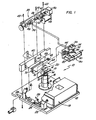
- the present invention is embodied in a video recorder-playback machine 10 having suitable optical and electronic elements for recording and playback of video information from a video information disc 14.
- the information disc 14 is removably supported within the machine upon a spindle assembly 18 for controlled and accurate high speed rotation of the disc during the recording and playback operations.
- a clamp assembly 20 operates to clamp the disc 14 in a precisely centered position upon the spindle assembly 18 for accurate, high speed disc rotation without slippage.
- the machine 10, including the spindle assembly 18 of this invention, comprises an improvement over the prior art in that the spindle assembly 18 is designed for consistent and accurate rotation of the information disc 14 with respect to the vertical axis of the spindle assembly at a relatively high rotational speed without substantial radial eccentricities.
- the spindle assembly 18 is relatively simple in design and assembly, and is consistently smooth running without significant vibration or undue wear of components.
- the spindle assembly 18 is thus uniquely adapted for use in a video recorder-playback machine 10 wherein consistent and accurate rotation of an information disc 14 is a prerequisite to avoid cross talk between information tracks on the disc.
- the video recorder-playback machine 10 includes a machine base or table 12 which provides support for a relatively high power laser generator unit 16, such as an argon ion laser, for use in recording a prescribed video information signal upon the disc 14.
- the high power laser generator unit 16 emits a highly amplified collimated beam of light for redirection by a suitable mirror assembly 22 to an electronically driven modulator 24.
- the modulator 24 is driven by a suitable frequency modulated electronic signal supplied via an imput lead 26 wherein the electronic signal is representative of the desired video information.
- the modulator 24 responds to the electronic signal to interrupt appropriately the amplified beam of light to pass a correspondingly modulated optical signal beam. This resultant optical signal beam is therefore representative of the prescribed video information.
- the electronic signal comprises a composite audio-video signal of the type commonly used in television transmissions and which, when supplied to the modulator 24, yields an optical signal beam representative of the composite audio and video information.
- the electronic signal comprises a composite audio-video signal of the type commonly used in television transmissions and which, when supplied to the modulator 24, yields an optical signal beam representative of the composite audio and video information.
- all further reference herein will be to video information.
- the modulated optical signal beam is incident upon a second mirror assembly 28 for redirection to a mobile optics carriage 30.
- This optics carriage 30 includes an angularly disposed dichroic mirror 32 for reflection of the optical signal beam in an upward direction for passage through an optical record-playback head 34.
- the record-playback head 34 carries an objective lens assembly 36 for focusing the optical signal beam to a precise spot on the underside of the video information disc 14.
- the optics carriage 30 is movably positioned by a carriage drive assembly 38 along a path in a radial direction with respect to the disc 14.
- the record-playback head 34 is movably positioned with respect to the disc 14 along a radius of the disc to control the point of focusing of the optical signal beam upon the disc.
- the carriage drive assembly 38 comprises a precision lead screw 48 supported for rotation by a bracket 50 which can be secured to a frame 40 and to the machine table 12 by a plurality of bolts 42.
- the lead screw 48 threadably receives a lead screw nut 52 coupled via a nonrotational coupling indicated at 54 to a sleeve-type push block 46 received freely about the lead screw 48. As illustrated, this push block 46 is secured to an upright wall 44 of the optics carriage 30.
- the lead screw 48 is oriented in a direction parallel with the required radial direction of movement of the optics carriage 30.
- a relatively slow speed reversible motor 56 and a relatively high speed reversible motor 58 are connected to the lead screw 48 through a selective clutch unit 60, and this clutch unit is operated to control driving of the lead screw 48 about its own axis either at a relatively slow or relatively fast speed of rotation.
- the optics carriage 30 is driven by the lead screw 48 in a radially outward direction with respect to the disc 14 whenever the lead screw 48 is rotated to cause the lead screw nut 52 to push against the push block 46.
- the lead screw is rotated in an opposite direction, the lead screw nut 52 travels along the screw in an opposite direction.
- the carriage 30 is secured by pins 62 to a linear slide member 64 which is urged in the radially inward direction with respect to the disc 14 by a constant tension band spring 66 wound about a barrel 68 secured to the frame 40.
- the slide member 64 is slidably mounted on a linear track member 70 secured to the frame 40 and adapted to accommodate linear movement of the optics carriage 30 in both the radially inward and the radially outward directions.
- the video information disc 14 is received upon the spindle assembly 18 of this invention for relatively high speed rotation of the disc about the vertical axis of the spindle assembly 18, as will be described herein in more detail.
- This rotation of the disc occurs simultaneously with linear movement of the optics carriage 30 in response to operation of the carriage drive assembly 38.
- the optical signal beam is focused upon the underside of the video information disc 14 by the radially traversing record-playback head 34 on the optics carriage 30 simultaneously with high speed rotation of the disc.
- the optical signal beam is focused upon the disc along a spiraling pattern of closely spaced tracks.
- the disc 14 includes a photosensitive coating, such as a layer of thin metal or a photoresist material, adapted to be physically altered by the high power optical signal beam whereby the optical signal beam is physically recorded upon the disc as a pattern of discontinuities representative of the prescribed video information.
- a photosensitive coating such as a layer of thin metal or a photoresist material
- the disc is rotated at a speed on the order of about 1800 rpm, and the closely spaced tracks are formed to have a width on the order of about 0.5 microns and a center-to-center spacing of about 1.5 microns.
- the clamp assembly 20 is provided for clamping the video information disc 14 securely upon the spindle assembly 18 for accommodating the high speed rotation of the disc without slippage.
- the clamp assembly also includes means for centering the disc upon the spindle assembly for accurate high speed rotation of the disc without substantial radial eccentricities with respect to the spindle assembly.
- a relatively low power laser generator unit 80 such as a helium-neon laser, is mounted directly upon the optics carriage 30 for use in retrieving or playing back the recorded video information from the disc 14.
- This low power laser generator unit 80 emits an amplified and collimated beam of light for reflection off the disc 14 whereby the reflected optical beam comprises a modulated playback beam which is alternately reflected and nonreflected in accordance with the recorded video information.
- This modulated playback beam is of sufficiently low power to avoid physical alteration of the photosensitive coating on the disc 14.
- the amplified beam of light from the low power laser generator unit 80 is redirected by a suitable mirror assembly 82 on the optics carriage 30 for appropriate incidence upon an angularly oriented mirror 84 which reflects the beam upwardly through the dichroic mirror 32 for focusing upon the disc 14 by the record-playback head 34.
- the reflected modulated playback beam is returned through the head 34 and by the mirror 84 to appropriate optical and electronic components 86 for demodulating the playback beam to the form of an electronic signal representative of the prescribed video information.
- This electronic signal can be supplied to an appropriate video display device, such as a television receiver, for playback of the recorded video information.
- playback can occur independent of the recording function or substantially simultaneously with the recording function to serve as a check of the recording resolution.
- the spindle assembly 18 of this invention is provided for supporting the information disc 14 for rotation about a precise vertical axis without significant radial eccentricities so as to allow accurate rotation of the disc with respect to the record-playback head 34.
- the spindle assembly 18 thus maintains the proper position of the disc during rotation with respect to the optical beams for precision recording and playback without cross talk between the closely spaced tracks.
- the spindle assembly 18 is shown in detail in Figs. 2-6, and comprises a vertically extending spindle shaft 72 supported for rotation about a precise vertical axis 71 within a complementary-shaped spindle housing 78.
- the spindle shaft 72 is formed from a unitary piece of stainless steel or the like, and is shaped to include a rod-shaped lower end 73 sized and shaped for reception downwardly into an electric drive motor 75 for driving the spindle shaft 72 at a relatively high rotational speed on the order of about 1800 rpm.
- This drive motor 75 comprises a high speed dc motor for applying a rotational torque to the lower end 73 of the shaft 72 without physical contact with the shaft. In this manner, the shaft is driven at the high rotational speed with minimum frictional resistance and minimum vibration between the motor 75 and the shaft 72.
- the lower end 73 of the shaft 72 merges upwardly into a journal 77 having a generally inverted and truncated conical shape for supportive engagement with the spindle housing 78.
- This journal 77 in turn is shaped to define an upwardly presented annular shoulder 74 for vertically supporting the information disc 14.
- An upper stud 76 projects upwardly from the journal 77 coaxially with the vertical axis 71 and is receivable through the central opening 15 of the information disc 14 for locating the disc upon the spindle assembly. As illustrated in Figs. 1 and 2, this stud 76 is adapted for cooperation with the clamp assembly 20 for centering and clamping the disc in position.
- the journal 77 of the spindle shaft 72 includes at its lower end an axially and downwardly presented shoulder 88. From the shoulder 88, the journal 77 extends upwardly and radially expands continuously over its height to define the truncated inverted conical shape.
- This conical journal 77 is received within the spindle housing 78 which includes a radially inwardly presented bearing surface 90 of a truncated conical configuration.
- this housing bearing surface 90 is formed to correspond mating- ly with the journal 77 whereby the journal 77 is supported within the housing 78 for accurate rotation about the vertical axis 71.
- journal 77 and the bearing surface 90 enable the journal to accommodate both radial loads and downwardly directed axial thrust loads during operation.
- the major portion of the bearing surface area of the journal 77 namely, the larger diameter upper portion of the journal, is located at the top of the journal adjacent the major portion of the load to be supported by the journal, namely, the information disc 14 on the stud 76.
- the spindle housing 78 is formed by a vertical stack of a plurality of housing sections, with three sections 92, 94, and 96 being illustrated in the drawing. These sections all include a radially inwardly presented bearing surface formed coaxially with the vertical axis 71 of spindle shaft rotation, and which, together with the corresponding bearing surfaces of the other housing sections, combine to define the conical bearing surface 90 for supporting the journal 77.
- upper and lower ones 92 and 96 of the housing sections are respectively secured to the intermediate housing section 94 by a plurality of bolts 91 and 93.
- a thin disc-shaped shim 98 is interposed between the upper and intermediate housing sections 92 and 94, and another thin disc-shaped shim 100 is interposed between the intermediate and lower housing sections 94 and 96.
- These shims 98 and 100 are appropriately sized and shaped to adjust the elevational positions between their respective housing sections so as to yield close conformance of the housing bearing surfaces 90 with the shape of the journal 77.
- accurate and constant rotation of the journal 77 about the vertical axis 71 is assured.
- the intermediate housing section 94 includes a radially projecting air inlet port 102 for suitable coupling to a supply (not shown) of air under pressure.
- This inlet port 102 supplies the air to an open flow riser 104 extending the height of the intermediate housing section 94.
- This flow path in turn openly communicates without orificing with an upwardly open slotted annular recess or flow path 106 at the upper end of the section 94, and with a downwardly open slotted annular recess or flow path 108 at the lower end of the section 94.
- the two slotted recesses 106 and 108 are annularly positioned for open flow communication with a plurality of radially inwardly open notches 110 and 112 formed respectively in the adjacent shims 98 and 100.
- These notches 110 and 112 in the shims provide a plurality of flow paths for the air under pressure from the associated recesses 106 and 108 in a radially inward direction into direct communication with the interface between the journal 77 and the housing bearing surface 90.
- the pressurized air is supplied to the journal-bearing surface interface substantially uniformly about the journal and at a plurality of vertically spaced locations along the height of the journal.
- this pressurized air is required to flow upwardly and downwardly along this interface whereby the journal is rotatably supported during operation by an annular and continuous film of air.
- the lower housing section 96 of the spindle housing 78 includes a lower annular and recessed shoulder 114 for reception of a base ring 116. As shown, this base ring 116 is secured to the lower housing section 96 by the bolts 93, and is in turn secured to the machine table 12 by a plurality of bolts 118. In this manner, the spindle assembly 18 is securely fixed in position upon the machine.
- a lower cylindrical thrust plate 120 is provided for accommodating vertically upward thrust loads upon operation of the spindle assembly 18. More specifically, this thrust plate 120 is secured to the downwardly presented shoulder 88 of the journal by a plurality of screws 122, preferably with an appropriately sized shim 124 interposed between the shoulder 88 and the thrust plate 120.
- This thrust plate is sized to include an upper bearing surface in running engagement with the underside of the base ring 116. Conveniently, as illustrated in Fig. 4, pressurized air is supplied to this bearing interface via a flow path 126 in the lower housing section 96 in alignment with the flow riser 104 in the intermediate housing section 94. This lower flow path 126 supplies a portion of the compressed air to an annular slot 128 which communicates via an annular leakage path 130 with the interface between the thrust plate 120 and the base ring 116.
- the spindle assembly 18 of this invention thus provides a relatively simple and thereby relatively inexpensive assembly for accurately supporting a video information disc for accurate and smooth- running rotation about a precise vertical axis.
- the rotation of the spindle assembly is substantially friction free so as to isolate the information disc from machine and/or system vibrations which can otherwise create cross talk when the machine is operated in recording or playback modes.
- the conical journal 77 rides on an air bearing surface to accommodate radial loads and axially downward thrust loads, and the thrust plate 120 rides on an air bearing surface to accommodate axially upward thrust loads.
- the pressurized air forming the air bearings is supplied without throttling or orificing through a plurality of internal flow paths and the slotted annular recesses formed within the spindle housing directly to the appropriate bearing surface.
- the lack of orificing of the air prior to supply to the bearing surface yields substantially uniform air flow to all of the bearing surfaces to result in smooth vibration free spindle shaft rotation.
Landscapes
- Holding Or Fastening Of Disk On Rotational Shaft (AREA)
- Rotational Drive Of Disk (AREA)
- Signal Processing For Digital Recording And Reproducing (AREA)
- Indexing, Searching, Synchronizing, And The Amount Of Synchronization Travel Of Record Carriers (AREA)
- Recording Or Reproducing By Magnetic Means (AREA)
- Magnetic Bearings And Hydrostatic Bearings (AREA)
- Sliding-Contact Bearings (AREA)
- Iron Core Of Rotating Electric Machines (AREA)
Claims (8)
Priority Applications (1)
| Application Number | Priority Date | Filing Date | Title |
|---|---|---|---|
| AT86111858T ATE53141T1 (de) | 1980-10-20 | 1981-10-20 | Antriebsspindel fuer ein videoaufzeichnungs-/wiedergabeger|t. |
Applications Claiming Priority (2)
| Application Number | Priority Date | Filing Date | Title |
|---|---|---|---|
| US198695 | 1980-10-20 | ||
| US06/198,695 US4339814A (en) | 1980-10-20 | 1980-10-20 | Spindle assembly for a video recorder-playback machine |
Related Parent Applications (1)
| Application Number | Title | Priority Date | Filing Date |
|---|---|---|---|
| EP81108586.9 Division | 1981-10-20 |
Publications (3)
| Publication Number | Publication Date |
|---|---|
| EP0213603A2 EP0213603A2 (de) | 1987-03-11 |
| EP0213603A3 EP0213603A3 (en) | 1987-06-24 |
| EP0213603B1 true EP0213603B1 (de) | 1990-05-23 |
Family
ID=22734411
Family Applications (3)
| Application Number | Title | Priority Date | Filing Date |
|---|---|---|---|
| EP86111858A Expired - Lifetime EP0213603B1 (de) | 1980-10-20 | 1981-10-20 | Antriebsspindel für ein Videoaufzeichnungs-/-wiedergabegerät |
| EP85111046A Expired - Lifetime EP0182021B1 (de) | 1980-10-20 | 1981-10-20 | Antriebsspindel für ein Videoaufzeichnungs-/-wiedergabegerät |
| EP81108586A Expired EP0050368B1 (de) | 1980-10-20 | 1981-10-20 | Antriebsspindel für ein Video-Aufzeichnungs-Wiedergabe-Gerät |
Family Applications After (2)
| Application Number | Title | Priority Date | Filing Date |
|---|---|---|---|
| EP85111046A Expired - Lifetime EP0182021B1 (de) | 1980-10-20 | 1981-10-20 | Antriebsspindel für ein Videoaufzeichnungs-/-wiedergabegerät |
| EP81108586A Expired EP0050368B1 (de) | 1980-10-20 | 1981-10-20 | Antriebsspindel für ein Video-Aufzeichnungs-Wiedergabe-Gerät |
Country Status (10)
| Country | Link |
|---|---|
| US (1) | US4339814A (de) |
| EP (3) | EP0213603B1 (de) |
| JP (3) | JPS5788575A (de) |
| KR (1) | KR850001017B1 (de) |
| AT (2) | ATE52870T1 (de) |
| AU (1) | AU538745B2 (de) |
| BR (1) | BR8104926A (de) |
| DE (2) | DE3177188D1 (de) |
| HK (3) | HK20991A (de) |
| SG (1) | SG12991G (de) |
Families Citing this family (10)
| Publication number | Priority date | Publication date | Assignee | Title |
|---|---|---|---|---|
| CA1159150A (en) * | 1980-10-20 | 1983-12-20 | Richard L. Wilkinson | Video recorder-playback machine |
| JPS6026676U (ja) * | 1983-07-28 | 1985-02-22 | 日本精工株式会社 | 磁気ディスク記憶装置 |
| US4509160A (en) * | 1983-12-05 | 1985-04-02 | Eggers Fred S | Disc drive assembly |
| JPS61227266A (ja) * | 1985-04-01 | 1986-10-09 | フレツド エス エツガ−ス | デイスク駆動組立体 |
| JPS62112320U (de) * | 1986-01-06 | 1987-07-17 | ||
| DE69018856T2 (de) * | 1989-02-24 | 1995-08-24 | Conner Peripherals Inc | Nasses Festplatten-Laufwerk mit einem konischen Spindellager. |
| US5239892A (en) * | 1990-08-27 | 1993-08-31 | Mitutoyo Corporation | Rotating device |
| ZA922942B (en) * | 1991-04-29 | 1993-11-23 | Trico Folberth Ltd | Housing for a rotatable shaft |
| JP4946108B2 (ja) * | 2006-03-17 | 2012-06-06 | 凸版印刷株式会社 | ディスク収納体及び冊子体 |
| US8740461B2 (en) * | 2011-04-18 | 2014-06-03 | Carpe Diem Technologies, Inc. | Fluid bearing assembly |
Family Cites Families (17)
| Publication number | Priority date | Publication date | Assignee | Title |
|---|---|---|---|---|
| US2018911A (en) * | 1934-06-29 | 1935-10-29 | Insulite Co | Composite construction material and method of making the same |
| DE880070C (de) * | 1943-02-21 | 1953-06-18 | Presswerk A G | Verfahren zur Herstellung von aus einzelnen Segmenten zusammengesetzten Fuehrungsbuchsen oder von aehnlichen aus Kunststoff bestehenden Hohlkoerpern |
| DE806077C (de) * | 1949-09-09 | 1951-06-11 | Kaiserslautern Guss Armatur | Lager fuer Wellen mit aus Streifen bestehender Lagerflaeche |
| DE1183744B (de) * | 1960-06-24 | 1964-12-17 | Linde Eismasch Ag | Gasgeschmiertes, statisches Gleitlager |
| US3186774A (en) * | 1962-09-04 | 1965-06-01 | Roy M Wilcox | Hydrostatic gas bearings |
| US3201181A (en) * | 1963-02-28 | 1965-08-17 | Ind Tectonics Inc | Hydrostatic bearing |
| NL6815035A (de) * | 1967-10-24 | 1969-04-28 | ||
| GB1221700A (en) * | 1968-12-24 | 1971-02-03 | Gamet Products Ltd | Improvements in or relating to hydrostatic bearing assemblies |
| GB1331283A (en) * | 1970-10-09 | 1973-09-26 | Horstmann Gear Co Ltd | Fluid bearings |
| GB1351841A (en) * | 1971-03-02 | 1974-05-01 | Horstmann Gear Co Ltd | Fluid bearings |
| US4132414A (en) * | 1972-02-07 | 1979-01-02 | Jack Dinsdale | Gramophone turntable apparatus |
| GB1420322A (en) * | 1972-04-19 | 1976-01-07 | Rca Corp | Turntable rotation in a vacuum atmosphere |
| FR2278128A1 (fr) * | 1974-07-08 | 1976-02-06 | Lencot Gerard | Plateau d'entrainement de machine phonographique sur paliers aerostatiques |
| GB1507107A (en) * | 1975-05-26 | 1978-04-12 | Tokyo Shibaura Electric Co | Bearing device |
| JPS54151004A (en) * | 1978-05-18 | 1979-11-27 | Aaru Ando Deii Ofuisu Makoto Y | Turntable device for record disk player |
| GB1596435A (en) * | 1978-05-31 | 1981-08-26 | Tiefenbrun J | Spindle assembly for gramophone record playing apparatus |
| US4252327A (en) * | 1979-02-16 | 1981-02-24 | Mca Discovision, Inc. | Video disc player |
-
1980
- 1980-10-20 US US06/198,695 patent/US4339814A/en not_active Expired - Lifetime
-
1981
- 1981-06-08 KR KR1019810002036A patent/KR850001017B1/ko not_active Expired
- 1981-07-02 AU AU72497/81A patent/AU538745B2/en not_active Expired
- 1981-07-30 BR BR8104926A patent/BR8104926A/pt not_active IP Right Cessation
- 1981-09-08 JP JP56140431A patent/JPS5788575A/ja active Granted
- 1981-10-20 AT AT85111046T patent/ATE52870T1/de not_active IP Right Cessation
- 1981-10-20 EP EP86111858A patent/EP0213603B1/de not_active Expired - Lifetime
- 1981-10-20 DE DE8686111858T patent/DE3177188D1/de not_active Expired - Lifetime
- 1981-10-20 AT AT86111858T patent/ATE53141T1/de not_active IP Right Cessation
- 1981-10-20 EP EP85111046A patent/EP0182021B1/de not_active Expired - Lifetime
- 1981-10-20 EP EP81108586A patent/EP0050368B1/de not_active Expired
- 1981-10-20 DE DE8585111046T patent/DE3177182D1/de not_active Expired - Lifetime
-
1985
- 1985-12-12 JP JP60280167A patent/JPS61148673A/ja active Granted
- 1985-12-12 JP JP60280168A patent/JPS61148674A/ja active Granted
-
1991
- 1991-02-25 SG SG129/91A patent/SG12991G/en unknown
- 1991-03-21 HK HK209/91A patent/HK20991A/en not_active IP Right Cessation
- 1991-04-11 HK HK273/91A patent/HK27391A/en not_active IP Right Cessation
- 1991-04-11 HK HK272/91A patent/HK27291A/en not_active IP Right Cessation
Also Published As
| Publication number | Publication date |
|---|---|
| EP0182021A2 (de) | 1986-05-28 |
| EP0182021B1 (de) | 1990-05-16 |
| EP0213603A2 (de) | 1987-03-11 |
| JPH0237013B2 (de) | 1990-08-22 |
| HK20991A (en) | 1991-03-28 |
| ATE53141T1 (de) | 1990-06-15 |
| HK27291A (en) | 1991-04-19 |
| EP0050368B1 (de) | 1988-06-01 |
| JPS5788575A (en) | 1982-06-02 |
| JPS61148673A (ja) | 1986-07-07 |
| EP0182021A3 (en) | 1986-08-27 |
| SG12991G (en) | 1991-04-05 |
| JPS6236295B2 (de) | 1987-08-06 |
| AU7249781A (en) | 1982-04-29 |
| JPS61148674A (ja) | 1986-07-07 |
| JPH0237012B2 (de) | 1990-08-22 |
| AU538745B2 (en) | 1984-08-23 |
| DE3177188D1 (de) | 1990-06-28 |
| HK27391A (en) | 1991-04-19 |
| EP0050368A1 (de) | 1982-04-28 |
| US4339814A (en) | 1982-07-13 |
| KR850001017B1 (ko) | 1985-07-18 |
| BR8104926A (pt) | 1982-08-31 |
| EP0213603A3 (en) | 1987-06-24 |
| ATE52870T1 (de) | 1990-06-15 |
| DE3177182D1 (de) | 1990-06-21 |
Similar Documents
| Publication | Publication Date | Title |
|---|---|---|
| KR850001020B1 (ko) | 비데오 녹화-재생 장치용 스핀들 고정장치 | |
| EP0213603B1 (de) | Antriebsspindel für ein Videoaufzeichnungs-/-wiedergabegerät | |
| US4337538A (en) | Drive assembly for a video recorder-playback machine | |
| US4422169A (en) | Lens assembly for a video recorder-playback machine | |
| KR850001019B1 (ko) | 비데오 녹화-재생장치용 스핀들 조립체 | |
| KR850001018B1 (ko) | 비데오 녹화-재생 장치용 스핀들 조립체 | |
| KR850001482B1 (ko) | 비데오 기록-재생 장치용 렌즈 조립체 | |
| KR850001022B1 (ko) | 비데오 녹화-재생 장치용 스핀들 고정장치 | |
| KR850001021B1 (ko) | 비데오 녹화-재생 장치용 스핀들 고정장치 | |
| KR850001382B1 (ko) | 비데오 녹화-재생장치 | |
| JPS5930268A (ja) | 円盤状記録媒体再生装置 | |
| KR850001385B1 (ko) | 비데오 녹화-재생장치 | |
| JPH01271941A (ja) | 光ディスク原盤記録装置 | |
| JPH10241244A (ja) | ターンテーブル装置 |
Legal Events
| Date | Code | Title | Description |
|---|---|---|---|
| PUAI | Public reference made under article 153(3) epc to a published international application that has entered the european phase |
Free format text: ORIGINAL CODE: 0009012 |
|
| 17P | Request for examination filed |
Effective date: 19860827 |
|
| AC | Divisional application: reference to earlier application |
Ref document number: 50368 Country of ref document: EP |
|
| AK | Designated contracting states |
Kind code of ref document: A2 Designated state(s): AT BE CH DE FR GB IT LI LU NL SE |
|
| PUAL | Search report despatched |
Free format text: ORIGINAL CODE: 0009013 |
|
| AK | Designated contracting states |
Kind code of ref document: A3 Designated state(s): AT BE CH DE FR GB IT LI LU NL SE |
|
| 17Q | First examination report despatched |
Effective date: 19881118 |
|
| GRAA | (expected) grant |
Free format text: ORIGINAL CODE: 0009210 |
|
| AC | Divisional application: reference to earlier application |
Ref document number: 50368 Country of ref document: EP |
|
| AK | Designated contracting states |
Kind code of ref document: B1 Designated state(s): AT BE CH DE FR GB IT LI LU NL SE |
|
| REF | Corresponds to: |
Ref document number: 53141 Country of ref document: AT Date of ref document: 19900615 Kind code of ref document: T |
|
| REF | Corresponds to: |
Ref document number: 3177188 Country of ref document: DE Date of ref document: 19900628 |
|
| ITF | It: translation for a ep patent filed | ||
| ET | Fr: translation filed | ||
| PLBE | No opposition filed within time limit |
Free format text: ORIGINAL CODE: 0009261 |
|
| STAA | Information on the status of an ep patent application or granted ep patent |
Free format text: STATUS: NO OPPOSITION FILED WITHIN TIME LIMIT |
|
| 26N | No opposition filed | ||
| ITTA | It: last paid annual fee | ||
| EPTA | Lu: last paid annual fee | ||
| EAL | Se: european patent in force in sweden |
Ref document number: 86111858.6 |
|
| PGFP | Annual fee paid to national office [announced via postgrant information from national office to epo] |
Ref country code: FR Payment date: 20001002 Year of fee payment: 20 |
|
| PGFP | Annual fee paid to national office [announced via postgrant information from national office to epo] |
Ref country code: SE Payment date: 20001003 Year of fee payment: 20 Ref country code: DE Payment date: 20001003 Year of fee payment: 20 |
|
| PGFP | Annual fee paid to national office [announced via postgrant information from national office to epo] |
Ref country code: GB Payment date: 20001004 Year of fee payment: 20 Ref country code: CH Payment date: 20001004 Year of fee payment: 20 Ref country code: AT Payment date: 20001004 Year of fee payment: 20 |
|
| PGFP | Annual fee paid to national office [announced via postgrant information from national office to epo] |
Ref country code: NL Payment date: 20001006 Year of fee payment: 20 |
|
| PGFP | Annual fee paid to national office [announced via postgrant information from national office to epo] |
Ref country code: LU Payment date: 20001013 Year of fee payment: 20 |
|
| PGFP | Annual fee paid to national office [announced via postgrant information from national office to epo] |
Ref country code: BE Payment date: 20001116 Year of fee payment: 20 |
|
| BE20 | Be: patent expired |
Free format text: 20011020 *DISCOVISION ASSOCIATES |
|
| PG25 | Lapsed in a contracting state [announced via postgrant information from national office to epo] |
Ref country code: LI Free format text: LAPSE BECAUSE OF EXPIRATION OF PROTECTION Effective date: 20011019 Ref country code: GB Free format text: LAPSE BECAUSE OF EXPIRATION OF PROTECTION Effective date: 20011019 Ref country code: CH Free format text: LAPSE BECAUSE OF EXPIRATION OF PROTECTION Effective date: 20011019 |
|
| PG25 | Lapsed in a contracting state [announced via postgrant information from national office to epo] |
Ref country code: NL Free format text: LAPSE BECAUSE OF EXPIRATION OF PROTECTION Effective date: 20011020 Ref country code: LU Free format text: LAPSE BECAUSE OF EXPIRATION OF PROTECTION Effective date: 20011020 Ref country code: AT Free format text: LAPSE BECAUSE OF EXPIRATION OF PROTECTION Effective date: 20011020 |
|
| PG25 | Lapsed in a contracting state [announced via postgrant information from national office to epo] |
Ref country code: SE Free format text: THE PATENT HAS BEEN ANNULLED BY A DECISION OF A NATIONAL AUTHORITY Effective date: 20011030 |
|
| REG | Reference to a national code |
Ref country code: GB Ref legal event code: PE20 Effective date: 20011019 |
|
| REG | Reference to a national code |
Ref country code: CH Ref legal event code: PL |
|
| EUG | Se: european patent has lapsed |
Ref document number: 86111858.6 |
|
| NLV7 | Nl: ceased due to reaching the maximum lifetime of a patent |
Effective date: 20011020 |