EP0214021A1 - Hydraulisch betätigte Kupplung - Google Patents
Hydraulisch betätigte Kupplung Download PDFInfo
- Publication number
- EP0214021A1 EP0214021A1 EP86401730A EP86401730A EP0214021A1 EP 0214021 A1 EP0214021 A1 EP 0214021A1 EP 86401730 A EP86401730 A EP 86401730A EP 86401730 A EP86401730 A EP 86401730A EP 0214021 A1 EP0214021 A1 EP 0214021A1
- Authority
- EP
- European Patent Office
- Prior art keywords
- clutch
- pressure
- valve
- pressure chamber
- fluid inlet
- Prior art date
- Legal status (The legal status is an assumption and is not a legal conclusion. Google has not performed a legal analysis and makes no representation as to the accuracy of the status listed.)
- Granted
Links
- 239000012530 fluid Substances 0.000 claims abstract description 54
- 238000001816 cooling Methods 0.000 claims abstract description 27
- 238000005461 lubrication Methods 0.000 claims description 23
- 230000001050 lubricating effect Effects 0.000 abstract 2
- 238000006243 chemical reaction Methods 0.000 description 7
- 230000008901 benefit Effects 0.000 description 5
- 230000008878 coupling Effects 0.000 description 2
- 238000010168 coupling process Methods 0.000 description 2
- 238000005859 coupling reaction Methods 0.000 description 2
- 230000009849 deactivation Effects 0.000 description 2
- 238000010586 diagram Methods 0.000 description 2
- 230000000694 effects Effects 0.000 description 2
- 238000011144 upstream manufacturing Methods 0.000 description 2
- 238000006073 displacement reaction Methods 0.000 description 1
- 230000008030 elimination Effects 0.000 description 1
- 238000003379 elimination reaction Methods 0.000 description 1
- 238000004519 manufacturing process Methods 0.000 description 1
- 210000000056 organ Anatomy 0.000 description 1
- 238000011084 recovery Methods 0.000 description 1
- 238000000926 separation method Methods 0.000 description 1
Images


Classifications
-
- F—MECHANICAL ENGINEERING; LIGHTING; HEATING; WEAPONS; BLASTING
- F16—ENGINEERING ELEMENTS AND UNITS; GENERAL MEASURES FOR PRODUCING AND MAINTAINING EFFECTIVE FUNCTIONING OF MACHINES OR INSTALLATIONS; THERMAL INSULATION IN GENERAL
- F16D—COUPLINGS FOR TRANSMITTING ROTATION; CLUTCHES; BRAKES
- F16D25/00—Fluid-actuated clutches
- F16D25/12—Details not specific to one of the before-mentioned types
- F16D25/123—Details not specific to one of the before-mentioned types in view of cooling and lubrication
-
- F—MECHANICAL ENGINEERING; LIGHTING; HEATING; WEAPONS; BLASTING
- F16—ENGINEERING ELEMENTS AND UNITS; GENERAL MEASURES FOR PRODUCING AND MAINTAINING EFFECTIVE FUNCTIONING OF MACHINES OR INSTALLATIONS; THERMAL INSULATION IN GENERAL
- F16D—COUPLINGS FOR TRANSMITTING ROTATION; CLUTCHES; BRAKES
- F16D67/00—Combinations of couplings and brakes; Combinations of clutches and brakes
- F16D67/02—Clutch-brake combinations
- F16D67/04—Clutch-brake combinations fluid actuated
Definitions
- the present invention relates generally to clutches, and in particular multi-disc clutches, the control of which is hydraulic.
- such a hydraulically controlled clutch comprises, overall, two coaxial parts, one, which forms for example a driving part, annularly equipped with one or more friction discs staggered axially, the other, which, then forming a driven part, comprises two parts in relation to cylinder-piston with respect to each other, said parts forming between them, on a first axial side of the friction disc or discs, a pressure chamber of variable volume capable of being supplied with pressurized fluid.
- the piston-forming part acts axially on the friction disc (s), for axial clamping of these discs and a reaction flange wedged axially on the cylinder-forming piece on the axial side of this or these friction discs opposite to the previous one.
- the pressurized fluid used is jointly serving a lubrication and / or cooling circuit, which benefits, in particular, for their cooling, the friction disc or discs.
- Hydraulically controlled clutches of this type find their application in particular for controlling a power take-off on tractors, said power take-off then being wedged on their led part.
- the corresponding hydraulic control comprises, in a hollow body, for serving one or the other of the two pressure chambers with variable volume required, that specific to engaging the clutch. , and that specific to the drag brake control, a fluid inlet, which is adapted to be connected to a source of pressurized fluid, and, interposed between said fluid inlet and one and the other of said chambers pressure, a valve, which, hereinafter referred to as a simple selection valve convenience, is under the control of an order available to the user.
- the drag brake pressure chamber may on the contrary be under pressure.
- the drag brake which is thus implemented and which is therefore also hydraulically controlled simply comprises a piston suitable for applying a braking pad against a bearing surface, generally cylindrical, integral in rotation with the part driven to control.
- the friction torque developed by such a drag brake can, at least for certain applications, prove to be insufficient.
- the present invention generally relates to a provision enabling it to dispense with the use of a band brake, or even any drag brake, even when the drag torque to be checked is , without other, relatively important.
- a clutch with hydraulic control of the kind whose hydraulic control comprises, in a hollow body, for serving at least one volume pressure chamber variable specific to the engagement of the clutch, a fluid inlet suitable for being connected to a source of pressurized fluid, in cooperation with a lubrication and / or cooling circuit also served by a fluid inlet, this clutch being d '' generally characterized in that, between the lubrication and / or cooling circuit and the inlet of fluid serving it is interposed a valve, which, hereinafter called simply for convenience control valve, is normally open, and which is likely to be subjected during closing to a pressure linked to the inlet pressure of the pressurized fluid when the clutch is disengaged.
- the clutch when, the clutch being in the disengaged position, and when the friction disc or discs are thus released and therefore inactive, the need for their cooling is less imperative, the lubrication circuit and / or corresponding cooling is systematically deactivated.
- the drag torque due to this lubrication and / or cooling circuit being therefore, at the appropriate time, reduced, it is advantageously possible to be satisfied, for the constitution of the drag brake, with a simple piston suitable for applying a simple braking pad against the relevant range of the part led to control, or even, at least for certain applications, to get rid of such a drag brake.
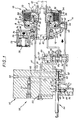
- the clutch 10 comprises a fixed support 12, and, rotatably mounted relative thereto, two coaxial parts A, B, one driving, the other driven.
- the driving part A itself comprises, in this embodiment, a hub 14, which, by its internal bore 15, grooved for this purpose, is capable of being locked in rotation on a shaft 16, in practice a driving shaft, for example the output shaft of an engine, and, annularly arranged around this hub 14 while being locked in rotation thereon, at least one friction disc 17.
- the driven part B comprises, as a corollary, two parts 19, 20 which, in relation to the cylinder-piston relative to one another, form between them, on a first axial side of the friction discs 17, a chamber pressure variable volume 21, capable, through a conduit 22, and according to arrangements described in more detail later, to be connected to a source of pressurized fluid.
- the part 19, which forms a cylinder comprises a hub 23, by which it is rotatably mounted in an internal bore 24 of the fixed support 12, and, around the friction discs 17, connected to the means 23 by a transverse wall forming a bottom .25, a skirt 26.
- This skirt 26, which extends axially beyond the friction discs 17, has, longitudinally, grooves 27 by virtue of which plates 28 are wedged in rotation thereon which alternate axially with said friction discs 17.
- reaction flange 30 On the axial side of these friction discs 17 opposite to the pressure chamber 21 extends, transversely, a reaction flange 30, which, thanks to the same grooves 27 in the skirt 26 of the part forming cylinder 19, is located stalled in rotation thereon.
- This reaction flange 30, which, by an internal bore 31, grooved for this purpose, is itself capable of being locked in rotation on a shaft 32, in practice a driven shaft forming a power take-off, is also axially wedged , at least in one direction, on said skirt 26.
- a washer 33 of the washer type opened radially by a slot, can be used for this purpose, said washer 33 being engaged both with a groove 34 of the cylindrical skirt 26 of the part forming cylinder 19 with a groove 35 in the reaction flange 30.
- the washer 33 thus implemented from being able to close unexpectedly on itself, at the risk of an axial separation of the reaction flange 30 from the cylindrical part 19, it may be associated with a ring , not clearly visible in the figures, which, introduced for example tangentially through an opening provided for this purpose in the reaction flange 30, fills the gap between it and the bottom of the groove 35 thereof.
- the part 20, which forms the piston, and which is an annular part, is slidably engaged, in a substantially sealed manner, between, on the one hand, the skirt 26 of the part forming the cylinder 19, and on the other hand, an extension internal axial 36 of the hub 23.
- this piston-forming part 20 On its face opposite to the pressure chamber 21, this piston-forming part 20 is subjected to elastic return means which permanently urge it in the direction opposite to the friction discs 17, that is to say in the direction of the wall. corresponding transverse 25 of the cylinder-forming part 19.
- these elastic return means consist of a spring 37 which bears on a bush 38 which is itself axially wedged on the internal axial extension 36 of the hub 23.
- the drag brake 11 meanwhile, comprises, in the embodiment shown, and this is an advantage of the invention, a simple piston 42, which is slidably mounted in a cylinder 43 formed for it in the fixed support 12, by defining with the bottom of this cylinder 43 a variable-volume pressure chamber '44 capable, via a conduit 45 and according to arrangements described in more detail later, of being connected to a source of pressurized fluid, and which is capable of applying a simple braking pad 46 against a bearing surface 47, in cylindrical practice, axially integral with the driven part B of the clutch 10.
- this bearing 47 is formed by a portion of the outer surface of the skirt 26 of the part forming a cylinder 19 belonging to this driven part B.
- This hydraulic control 50 is formed in a hollow body 51.
- This hollow body 51 which was only schematically shown in the figures and the production of which moreover falls within the skill of the art, can form an independent part of the fixed support 12 of the clutch 10, as shown.
- the hydraulic control 50 comprises, in the hollow body 51, for serving one at least of the two pressure chambers 21,44 concerned, and, in practice, one or the other of these, a fluid inlet 52, suitable for being connected to any source of pressurized fluid.
- valve 53 interposed between this fluid inlet 52 and one and the other of the pressure chambers 21, 44, a valve 53, called here for simple convenience, selection valve.
- this selection valve 53 which is under the control of a control 54, in this case a simple rod, available to a user, is a slide valve.
- Its drawer 55 is mounted axially movable in a recess 56, forming a cylinder, of the hollow body 51.
- It has a plurality of spans, and mainly two spans 57, 58, one disposed at its end, the other disposed in its middle part.
- the drawer 55 also comprises, between these spans 57, 58, an intermediate span 59, but, the latter, which, axially, is affected by grooves, having no practical role in practice, it will no longer be mentioned here.
- the pipe 60 connects this recess forming a cylinder 56 to the fluid inlet 52, the pipe 61 connects it to the conduit 22 serving the pressure chamber 21 of the clutch 10, the pipe 62 connects it to the pipe 45 serving the pressure chamber 44 of the drag brake 11 and the pipe 63 connects it to a discharge.
- this discharge is constituted by a casing, not shown, in which the assembly of the clutch 10, of its drag brake 11, and of its hydraulic control 50 is disposed, this casing jointly constituting the source of pressure fluid. associated, by recovery, by a pump also not shown, of the fluid, in this case the oil, which is there.
- the pressure chamber 21 of the clutch 10 is connected to the fluid inlet 52, so that, driven back in the direction of the reaction flange 30, the piece forming the piston 20 clamps axially against this the last stack formed by the friction discs 17 and the plates 28 inserted between them, and that said clutch 10 is therefore engaged.
- a valve 72 engaged with the pipe 60, ensures the adjustment to a given value of the pressure then prevailing in the entire circuit concerned, and therefore in the pressure chamber 21 of the clutch 10, this value being chosen sufficient to satisfy the axial tightening to be ensured .
- valve 72 The pressure thus governed by the valve 72 is in any event linked to the inlet pressure of the pressurized fluid, since it is derived therefrom.
- a hydraulic accumulator 73 whose internal cavity 74, formed between a cylinder 75 belonging to the fixed support 12 and a piston 76 movably mounted in this cylinder 75 at the against elastic return means 78, is engaged with the duct 22 serving the pressure chamber 21 of this clutch 10.
- the range 58 of the drawer 55 interrupts any communication between the lines 62 and 63, while, by, the cylinder-forming recess 56, the line 62 is in communication with the line 60 served by the fluid inlet 52 .
- the pressure chamber 44 of the drag brake 11 is then under pressure, and, while the clutch 10 is disengaged, the drag brake 11 is applied.
- a lubrication and / or cooling circuit 80 also suitably served by a fluid inlet.
- this lubrication and / or cooling circuit 80 is served, in the embodiment shown, by the same fluid inlet 52 as the pressure chamber 21 of the clutch 10 and that 44 of the drag brake 11.
- valve 87 which, here called for simple convenience control valve, is normally open, and which is capable of being subjected in closing to a pressure linked to the inlet pressure of the fluid under pressure when clutch 10 is disengaged.
- this control valve 87 is subjected in closing to a pressure linked to that prevailing in the pressure chamber 44 of the drag brake 11, when, as in the present case, such a drag brake is actually implemented.
- control valve 87 is a slide valve, the slide 88 of which, movably mounted in a recess forming a cylinder 89 of the hollow body 51, is, at one of its ends, subjected to elastic means return 90 which urges it permanently towards its other end, and is subjected, at its said other end, to the pressure prevailing in the pressure chamber 44 of the drag brake 11.
- the elastic return means 90 are constituted by a spring, which bears on one of the ends of the recess forming a cylinder 89, while, by a tail 91, the drawer 88 is clean coming into abutment on the other end of this recess forming cylinder 89.
- the drawer 88 has in practice only two ranges 92, 93.
- the pipeline 81 serving the lubrication and / or cooling circuit 80 passes through the recess forming the cylinder 89, with its outlets 81 T , 81 L therein capable of being isolated from one another by the drawer 88.
- the cylinder-shaped recess 89 On the side of the spring 90 constituting the elastic return means, the cylinder-shaped recess 89 is connected to the discharge by a pipe 95, while, on the side opposite this spring, said cylinder-shaped recess 89 is crossed, without the possibility of any occultation, via the pipe 62 serving the pressure chamber 44 of the drag brake 11.
- outlets 81 T , 81 L of the pipe 81 in the cylinder recess 89 are staggered axially with respect to each other, and the discharge line 95 is arranged axially on the other side of that 81 T of these outlets which is upstream relative to that 81 L which is downstream, the direction of circulation taken as a reference being that going from fluid inlet 52 to the lubrication and / or cooling circuit 80.
- FIGS. 1 and 2 For its rest position, FIGS. 1 and 2, for which, under the stress of the spring constituting its elastic return means 90, it is supported, by its tail 91, on the corresponding end of the recess forming cylinder 89, the slide 88 of the control valve 87 does not interfere with the pipe 81, and by its range 93, it puts the discharge pipe 95 out of service.
- the drag brake 11 when, according to the position of FIG. 3, the drag brake 11 is applied in order to stop the driven part B of the clutch 10 from rotating, necessary for the implementation of the PTO concerned, it results from the pressure then prevailing in the pressure chamber 44 of this drag brake 11, which is linked to the inlet pressure of the pressurized fluid in the hydraulic control 50 since it is then derived therefrom.
- the drawer 88 is interposed by its bearing 92 on the pipe 81 serving the lubrication and / or cooling circuit 80, by isolating one from the other its outlets 81 T , 81 L in the recess forming cylinder 89, which temporarily disables said lubrication and / or cooling circuit 80.
- the slide 88 then obscures by its reach 92 the downstream outlet 81 L of the pipe 81, while jointly putting its upstream outlet 81 T in communication with the discharge pipe 95, its scope 93 then being beyond its own outlet.
- the drag torque of which the driven part B to be stopped to be rotated is advantageously reduced, which allows, at least be satisfied, for this stop, with a drag brake 11 simply constituted, as described, by a piston 42 and a brake shoe 46.
- the piston 76 of the hydraulic accumulator 73 has a calibrated bore 98, from which advantageously results a slower displacement of this piston 76 when the clutch 10, and therefore an increase in the duration of its intervention.
- a valve closes the calibrated bore 98 after a determined stroke of the piston 76, the latter for example abutting against such a valve.
- the pressure to which the control valve implemented according to the invention is sensitive is not necessarily the pressure prevailing in the pressure chamber itself of the drag brake, but can on the contrary be any other pressure simply linked to the previous one.
- the temporary deactivation of the lubrication and / or cooling circuit can lead, if not to a total elimination of the drag torque, at least to a sufficient reduction of it so that it no longer need to apply any drag brake.
- the pipe 62 no longer passes through the cylinder-forming recess 89 of the control valve 82 but simply opens into the latter, at the relevant end of this cylinder-forming recess 89, so that this control valve 82 is then subjected in closing to the pressure prevailing in this pipe 62, which, when this pipe 62 is connected to the fluid inlet 52, is linked to the inlet pressure of the pressurized fluid in the hydraulic control 50 since it is then derived therefrom, this pressure being greater than that prevailing initially in the lubrication and / or cooling circuit 80, and therefore that prevailing in the recess forming cylinder 89, between the bearings 92, 93 of the drawer 87, and / or the corresponding sections of this drawer 87 being established accordingly.
- fluid inlet serving the lubrication and / or cooling circuit is not necessarily the same as those serving the clutch pressure chamber and that of the drag brake when such a drag brake is applied. implemented, but can on the contrary be distinct from it.
Landscapes
- Engineering & Computer Science (AREA)
- General Engineering & Computer Science (AREA)
- Mechanical Engineering (AREA)
- Hydraulic Clutches, Magnetic Clutches, Fluid Clutches, And Fluid Joints (AREA)
Applications Claiming Priority (2)
| Application Number | Priority Date | Filing Date | Title |
|---|---|---|---|
| FR8511850A FR2585791B1 (fr) | 1985-08-02 | 1985-08-02 | Embrayage a commande hydraulique |
| FR8511850 | 1985-08-02 |
Publications (2)
| Publication Number | Publication Date |
|---|---|
| EP0214021A1 true EP0214021A1 (de) | 1987-03-11 |
| EP0214021B1 EP0214021B1 (de) | 1989-10-18 |
Family
ID=9321906
Family Applications (1)
| Application Number | Title | Priority Date | Filing Date |
|---|---|---|---|
| EP19860401730 Expired EP0214021B1 (de) | 1985-08-02 | 1986-08-01 | Hydraulisch betätigte Kupplung |
Country Status (3)
| Country | Link |
|---|---|
| EP (1) | EP0214021B1 (de) |
| DE (1) | DE3666494D1 (de) |
| FR (1) | FR2585791B1 (de) |
Cited By (1)
| Publication number | Priority date | Publication date | Assignee | Title |
|---|---|---|---|---|
| EP0331362A1 (de) * | 1988-02-26 | 1989-09-06 | Arthur Knowles | Verzögerungsvorrichtung für Getriebeschaltung |
Families Citing this family (2)
| Publication number | Priority date | Publication date | Assignee | Title |
|---|---|---|---|---|
| WO2017207334A1 (en) | 2016-05-30 | 2017-12-07 | Volvo Truck Corporation | A clutch actuating arrangement |
| CN110392793B (zh) * | 2017-03-15 | 2020-12-29 | 沃尔沃卡车集团 | 用于将阀单元从气动控制的致动器装置断开的方法 |
Citations (5)
| Publication number | Priority date | Publication date | Assignee | Title |
|---|---|---|---|---|
| GB789285A (en) * | 1956-06-27 | 1958-01-15 | Gen Motors Corp | Improvements relating to power transmission mechanisms |
| US3463283A (en) * | 1966-01-06 | 1969-08-26 | Int Harvester Co | Hydraulic pressure control system for clutches |
| FR2403487A1 (fr) * | 1977-09-16 | 1979-04-13 | Ferodo Sa | Frein a enroulement pour organe tournant, et mecanisme, en particulier embrayage a commande hydraulique, notamment embrayage multidisque, a organe tournant equipe d'un tel frein |
| US4321990A (en) * | 1978-09-26 | 1982-03-30 | Caterpillar Tractor Co. | Hydrodynamic retarding brake and oil-cooled driveline clutch |
| EP0106594A1 (de) * | 1982-09-30 | 1984-04-25 | Deere & Company | Kupplungen |
-
1985
- 1985-08-02 FR FR8511850A patent/FR2585791B1/fr not_active Expired - Lifetime
-
1986
- 1986-08-01 DE DE8686401730T patent/DE3666494D1/de not_active Expired
- 1986-08-01 EP EP19860401730 patent/EP0214021B1/de not_active Expired
Patent Citations (5)
| Publication number | Priority date | Publication date | Assignee | Title |
|---|---|---|---|---|
| GB789285A (en) * | 1956-06-27 | 1958-01-15 | Gen Motors Corp | Improvements relating to power transmission mechanisms |
| US3463283A (en) * | 1966-01-06 | 1969-08-26 | Int Harvester Co | Hydraulic pressure control system for clutches |
| FR2403487A1 (fr) * | 1977-09-16 | 1979-04-13 | Ferodo Sa | Frein a enroulement pour organe tournant, et mecanisme, en particulier embrayage a commande hydraulique, notamment embrayage multidisque, a organe tournant equipe d'un tel frein |
| US4321990A (en) * | 1978-09-26 | 1982-03-30 | Caterpillar Tractor Co. | Hydrodynamic retarding brake and oil-cooled driveline clutch |
| EP0106594A1 (de) * | 1982-09-30 | 1984-04-25 | Deere & Company | Kupplungen |
Cited By (1)
| Publication number | Priority date | Publication date | Assignee | Title |
|---|---|---|---|---|
| EP0331362A1 (de) * | 1988-02-26 | 1989-09-06 | Arthur Knowles | Verzögerungsvorrichtung für Getriebeschaltung |
Also Published As
| Publication number | Publication date |
|---|---|
| DE3666494D1 (en) | 1989-11-23 |
| EP0214021B1 (de) | 1989-10-18 |
| FR2585791A1 (fr) | 1987-02-06 |
| FR2585791B1 (fr) | 1990-01-12 |
Similar Documents
| Publication | Publication Date | Title |
|---|---|---|
| EP3090190B1 (de) | Aktuator mit irreversiblem gewinde, trommelbremsaktuator und bremsvorrichtung mit so einem aktuator | |
| FR2796886A1 (fr) | Dispositif de palier de support d'une roue equipe de moyens de freinage | |
| FR2834043A1 (fr) | Ensemble de serrage perfectionne et coupleur hydraulique le comportant | |
| FR2549553A1 (fr) | Embrayage pour vehicule de travail tel que motoculteur | |
| FR2474624A1 (fr) | Transmission a organe d'accouplement hydraulique et embrayage de verrouillage, notamment pour vehicule automobile | |
| EP3087285B1 (de) | Verbesserte scheibenbremse mit einer hydraulisch betätigten feststellbremse und einer verschleisseinstellungseinheit | |
| EP0036216B1 (de) | Hydrodynamischer Drehmomentwandler mit Überbrückungsvorrichtung | |
| EP0002632B1 (de) | Verschleissnachstellvorrichtung für Bremsen und Bremse versehen mit einer solchen Vorrichtung | |
| FR2541742A1 (fr) | Systeme de freinage comprenant au moins un disque de frein coulissant et disque de frein pour un tel systeme de freinage | |
| EP0214021B1 (de) | Hydraulisch betätigte Kupplung | |
| EP3087286B1 (de) | Scheibenbremse mit einer parkbremse mit hydraulischer betätigung | |
| FR2780464A1 (fr) | Embrayage a friction a dispositif de rattrapage d'usure, notamment pour vehicule automobile | |
| FR2611842A1 (fr) | Embrayage a commande hydraulique et frein de trainee | |
| FR2862113A1 (fr) | Accouplement du type embrayage, notamment pour l'entrainement d'outils agricoles | |
| FR2661960A1 (fr) | Assemblage d'un couvercle d'embrayage a friction. | |
| EP3087288B1 (de) | Scheibenbremse mit hydraulischer steuerung mit einer feststellbremse mit hydraulischer betätigung | |
| FR2661721A1 (fr) | Embrayage autonome a friction avec disque mene a faible inertie. | |
| FR3015410A1 (fr) | Frein a disque comportant un frein de stationnement a actionnement hydraulique perfectionne | |
| EP3087287B1 (de) | Scheibenbremse mit einer feststellbremse mit hydraulischer betätigung und verschleissnachstelleinheit | |
| FR2586769A1 (fr) | Embrayage a commande hydraulique. | |
| EP3087289B1 (de) | Verbesserte scheibenbremse mit einer hydraulisch betätigten feststellbremse | |
| FR2798167A1 (fr) | Demarreur de vehicule automobile comportant un dispositif d'entrainement par friction | |
| FR3105327A1 (fr) | Dispositif de freinage à usure réduite | |
| FR2626638A1 (fr) | Embrayage a commande hydraulique du genre comportant un frein de trainee | |
| FR2834327A1 (fr) | Coupleur comportant des moyens d'etancheite et des moyens de protection de ceux-ci |
Legal Events
| Date | Code | Title | Description |
|---|---|---|---|
| PUAI | Public reference made under article 153(3) epc to a published international application that has entered the european phase |
Free format text: ORIGINAL CODE: 0009012 |
|
| AK | Designated contracting states |
Kind code of ref document: A1 Designated state(s): DE FR GB IT |
|
| 17P | Request for examination filed |
Effective date: 19870418 |
|
| 17Q | First examination report despatched |
Effective date: 19880510 |
|
| GRAA | (expected) grant |
Free format text: ORIGINAL CODE: 0009210 |
|
| AK | Designated contracting states |
Kind code of ref document: B1 Designated state(s): DE FR GB IT |
|
| REF | Corresponds to: |
Ref document number: 3666494 Country of ref document: DE Date of ref document: 19891123 |
|
| ITF | It: translation for a ep patent filed | ||
| GBT | Gb: translation of ep patent filed (gb section 77(6)(a)/1977) | ||
| PLBE | No opposition filed within time limit |
Free format text: ORIGINAL CODE: 0009261 |
|
| STAA | Information on the status of an ep patent application or granted ep patent |
Free format text: STATUS: NO OPPOSITION FILED WITHIN TIME LIMIT |
|
| 26N | No opposition filed | ||
| PGFP | Annual fee paid to national office [announced via postgrant information from national office to epo] |
Ref country code: GB Payment date: 19910729 Year of fee payment: 6 |
|
| ITTA | It: last paid annual fee | ||
| PGFP | Annual fee paid to national office [announced via postgrant information from national office to epo] |
Ref country code: DE Payment date: 19911002 Year of fee payment: 6 |
|
| PG25 | Lapsed in a contracting state [announced via postgrant information from national office to epo] |
Ref country code: GB Effective date: 19920801 |
|
| PGFP | Annual fee paid to national office [announced via postgrant information from national office to epo] |
Ref country code: FR Payment date: 19920805 Year of fee payment: 7 |
|
| GBPC | Gb: european patent ceased through non-payment of renewal fee |
Effective date: 19920801 |
|
| PG25 | Lapsed in a contracting state [announced via postgrant information from national office to epo] |
Ref country code: DE Effective date: 19930501 |
|
| PG25 | Lapsed in a contracting state [announced via postgrant information from national office to epo] |
Ref country code: FR Effective date: 19940429 |
|
| REG | Reference to a national code |
Ref country code: FR Ref legal event code: ST |
|
| PG25 | Lapsed in a contracting state [announced via postgrant information from national office to epo] |
Ref country code: IT Free format text: LAPSE BECAUSE OF NON-PAYMENT OF DUE FEES;WARNING: LAPSES OF ITALIAN PATENTS WITH EFFECTIVE DATE BEFORE 2007 MAY HAVE OCCURRED AT ANY TIME BEFORE 2007. THE CORRECT EFFECTIVE DATE MAY BE DIFFERENT FROM THE ONE RECORDED. Effective date: 20050801 |