EP0215190A1 - Schaltungsanordnung zum Abgleich der Messdiagonalspannung einer Widerstandsbrückenschaltung - Google Patents
Schaltungsanordnung zum Abgleich der Messdiagonalspannung einer Widerstandsbrückenschaltung Download PDFInfo
- Publication number
- EP0215190A1 EP0215190A1 EP86106689A EP86106689A EP0215190A1 EP 0215190 A1 EP0215190 A1 EP 0215190A1 EP 86106689 A EP86106689 A EP 86106689A EP 86106689 A EP86106689 A EP 86106689A EP 0215190 A1 EP0215190 A1 EP 0215190A1
- Authority
- EP
- European Patent Office
- Prior art keywords
- diagonal
- bridge
- voltage
- measurement
- circuit
- Prior art date
- Legal status (The legal status is an assumption and is not a legal conclusion. Google has not performed a legal analysis and makes no representation as to the accuracy of the status listed.)
- Granted
Links
Images
Classifications
-
- G—PHYSICS
- G01—MEASURING; TESTING
- G01R—MEASURING ELECTRIC VARIABLES; MEASURING MAGNETIC VARIABLES
- G01R17/00—Measuring arrangements involving comparison with a reference value, e.g. bridge
- G01R17/10—AC or DC measuring bridges
- G01R17/105—AC or DC measuring bridges for measuring impedance or resistance
Definitions
- the invention relates to a circuit arrangement for comparing the measurement diagonal voltage of a resistance bridge circuit according to the preamble of claim 1.
- a circuit arrangement for measuring the measurement diagonal voltage of a resistance bridge circuit in which a second arbitrarily detunable resistance bridge circuit is connected in parallel with respect to its supply and measurement diagonals.
- the detuning of the second bridge circuit necessary for the disappearance of a common measurement diagonal voltage is used, which is controlled by a tracking system connected to the common measurement diagonal voltage of both bridge circuits.
- the second resistance bridge circuit is separated at both supply points and the separation points are bridged with an additional bridge resistor.
- the connections of the additional resistors are connected by diagonally switchable contacts of two switches for the supply circuit.
- the duty cycle of the switching frequency is controlled by the tracking system.
- the invention was based on the object of specifying a circuit arrangement for comparing the measurement diagonal voltage of a resistance bridge circuit which does not require the aid of a second resistance bridge as a compensation device.
- the adjustment should take place with the highest possible resolution and be suitable for use in an automatically operating measuring device without mechanically moving parts. This object is achieved according to the invention with the features in the characterizing part of claim 1.
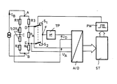
- the drawing shows a resistor bridge circuit with the resistors R1, R2, R3 and R4.
- a direct current I B is fed into a first bridge diagonal with the corner points A and B.
- At least one of the resistors R1 to R4 is a sensor that changes with the size to be measured.
- the bridge branch R3, R4 is separated at points D and E and bridged with a trimming resistor R A. For reasons of uniform current distribution, two fixed resistors 1/2 R A of the same size are inserted in the other bridge branch R1, R2.
- the end points D and E of the balancing resistor R A are each connected to an electronically controllable switch S1 and S2, the stationary contact parts of which are connected together in point F and connected to the input of a low-pass filter TP.
- Switches S1 and S2 are alternately switched on and off in opposite directions by a digital control signal.
- the control signal is supplied by a pulse width modulator PW.
- the measuring diagonal voltage U D present between the bridge point C and the output of the low-pass filter is fed to the input of an A / D converter A / D, which converts the measuring voltage U D into a corresponding digital value high accuracy.
- the digital value is fed to a control unit ST, which in turn influences the control signal of the pulse width modulator PW.
- a microprocessor module can be used as the control unit ST.
- the measurement diagonal voltage U D of the resistance bridge circuit is adjusted in a digitally operating system, consisting of the switches S1 and S2, the A / D converter A / D, the control unit ST and the pulse width modulator PW.
- This digital adjustment system replaces a mechanically adjustable potentiometer with the adjustment resistor R A , the division ratio of which is set using the two switches S1 and S2. Both switches are periodically switched on and off alternately by means of the control signal generated by the pulse width modulator PW with an adjustable pulse duty factor. If, in the limit case, the switch S1 is permanently closed and the switch S2 is open, the measured voltage between the bridge points C and D is set as the voltage value U D.
- the measurement voltage between the bridge points C and E appears as the voltage value U D.
- a measurement voltage U D is set which lies between the two measurement voltage limit values and which is linear with the duty cycle is dependent.
- the adjustment path of an analog adjustment potentiometer, which is dependent on the detuning of the resistance bridge circuit, is thus replaced by the digitally adjustable duty cycle of the control signal.
- the pulse duty factor is set in digital steps by the control unit ST as a function of the digital value of the measuring voltage U D determined by the A / D converter. Since the duty cycle is set discretely, so is the Resolution of the digitally working adjustment system in stages so that the desired bridge adjustment generally does not lead to the bridge diagonal voltage U D equal to zero. There remains a non-adjustable residual deviation which can be measured with the A / D converter A / D, so that the remaining calibration error can be determined by measurement.
- the residual deviation is linearly dependent on the size of the bridge current I B. This results in a measurement error if fluctuations in I B are not taken into account when determining the residual voltage with the A / D converter A / D.
- the reference voltage required for the A / D converter is derived from the voltage U A falling across the balancing resistor R A , the characteristic curve of the converter changes in the event of fluctuations in the bridge supply current I B. Residual deviation and reference voltage are proportional to I B , so that a change in I B leads to an equal percentage deviation both in the residual deviation and in the reference voltage. This completely compensates for the influence of I B errors when measuring the residual deviation.
- Integrating converters are suitable as A / D converters, for example converters operating according to the dual slope method.
Landscapes
- Physics & Mathematics (AREA)
- General Physics & Mathematics (AREA)
- Measuring Instrument Details And Bridges, And Automatic Balancing Devices (AREA)
- Measurement Of Resistance Or Impedance (AREA)
- Analogue/Digital Conversion (AREA)
Abstract
Description
- Die Erfindung bezieht sich auf eine Schaltungsanordnung zum Abgleich der Meßdiagonalspannung einer Widerstandsbrückenschaltung nach der Gattung des Anspruches 1.
- Aus der EP-OS 0 009 231 ist eine Schaltungsanordnung zur Messung der Meßdiagonalspannung einer Widerstandsbrückenschaltung bekannt, bei der eine zweite willkürlich verstimmbare Widerstandsbrückenschaltung hinsichtlich ihrer Speise- und Meßdiagonalen parallelgeschaltet ist. Als Maß für die Meßdiagonalspannung der ersten Brückenschaltung dient die zum Verschwinden einer gemeinsamen Meßdiagonalspannung notwendige Verstimmung der zweiten Brückenschaltung, die von einem an die gemeinsame Meßdiagonalspannung beider Brückenschaltungen angeschlossenen Nachlaufsystem gesteuert ist. Zu diesem Zweck ist die zweite Widerstandsbrückenschaltung an beiden Speisepunkten aufgetrennt und die Trennstellen mit je einem zusätzlichen Brückenwiderstand überbrückt. Die Anschlüsse der zusätzlichen Widerstände sind durch diagonal umschaltbare Kontakte zweier Umschalter für den Speisekreis verbunden. Das Tastverhältnis der Umschaltfrequenz wird vom Nachlaufsystem gesteuert.
- Der Erfindung lag die Aufgabe zugrunde, eine Schaltungsanordnung zum Abgleich der Meßdiagonalspannung einer Widerstandsbrückenschaltung anzugeben, die ohne das Hilfsmittel einer zweiten Widerstandsbrücke als Kompensationseinrichtung auskommt. Der Abgleich soll mit möglichst hoher Auflösung erfolgen und für den Einsatz in einem automatisch arbeitenden Meßgerät ohne mechanisch bewegte Teile geeignet sein. Die Lösung dieser Aufgabe gelingt erfindungsgemäß mit den Merkmalen im Kennzeichen des Anspruches 1.
- Die Erfindung wird anhand eines in der Figur dargestellten Ausführungsbeispieles näher erläutert.
- Die Zeichnung zeigt eine Widerstandsbrückenschaltung mit den Widerständen R1, R2, R3 und R4. An eine erste Brückendiagonale mit den Eckpunkten A und B wird ein Gleichstrom IB eingespeist. Von den Widerständen R1 bis R4 ist mindestens einer ein Meßfühler, der sich mit der zu messenden Größe ändert.
- Der Brückenzweig R3, R4 ist an den Punkten D und E aufgetrennt und mit einem Abgleichwiderstand RA überbrückt. Aus Gründen der gleichmäßigen Stromaufteilung sind im anderen Brückenzweig R1, R2 zwei in der Summe gleichgroße Festwiderstände 1/2 RA eingefügt.
- Die Endpunkte D und E des Abgleichwiderstandes RA sind mit je einem elektronisch steuerbaren Schalter S1 und S2 verbunden, deren ruhende Kontaktteile in Punkt F zusammengeschaltet und mit dem Eingang eines Tiefpasses TP verbunden sind. Die Schalter S1 und S2 werden durch ein digitales Steuersignal abwechselnd gegensinnig ein- und ausgeschaltet. Das Steuersignal liefert ein Pulsweitenmodulator PW. Die zwischen dem Brückenpunkt C und dem Ausgang des Tiefpasses anstehende Meßdiagonalspannung UD wird dem Eingang eines A/D-Umsetzers A/D zugeführt, der die Meßspannung UD in einen entsprechenden Digitalwert mit hoher Genauigkeit umsetzt. Der Digitalwert wird einer Steuereinheit ST zugeführt, die ihrerseits das Steuersignal des Pulsweitenmodulators PW beeinflußt. Als Steuereinheit ST kann ein Mikroprozessorbaustein verwendet werden.
- Der Abgleich der Meßdiagonalspannung UD der Widerstandsbrückenschaltung erfolgt in einem digital arbeitenden System, bestehend aus den Schaltern S1 und S2, dem A/D-Umsetzer A/D, der Steuereinheit ST und dem Pulsweitenmodulator PW. Dieses digital arbeitende Abgleichsystem ersetzt ein mechanisch einstellbares Potentiometer durch den Abgleichwiderstand RA, wobei dessen Teilerverhältnis mit Hilfe der beiden Schalter S1 und S2 eingestellt wird. Beide Schalter werden abwechselnd mittels des vom Pulsweitenmodulator PW generierten Steuersignales mit einstellbarem Tastverhältnis periodisch ein- und ausgeschaltet. Ist im Grenzfall der Schalter S1 dauernd geschlossen und der Schalter S2 geöffnet, so stellt sich als Spannungswert UD die zwischen den Brückenpunkten C und D herrschende Meßspannung ein. Entsprechend erscheint im umgekehrten Grenzfall als Spannungswert UD die Meßspannung zwischen den Brückenpunkten C und E. Bei einem gegebenen Tastverhältnis des Steuersignales zwischen diesen beiden Grenzfällen stellt sich eine Meßspannung UD ein, die zwischen den beiden bezeichneten Meßspannungs-Grenzwerten liegt und die linear vom Tastverhältnis abhängig ist. Damit ist der von der Verstimmung der Widerstandsbrückenschaltung abhängige Verstellweg eines analog arbeitenden Abgleichpotentiometers durch das digital einstellbare Tastverhältnis des Steuersignales ersetzt.
- Als Steuersignal dient ein Rechtecksignal mit einstellbarem Tastverhältnis, welches der Pulsweitenmodulator PW generiert. Die Einstellung des Tastverhältnisses erfolgt in digitalen Schritten durch die Steuereinheit ST in Abhängigkeit des vom A/D-Umsetzer ermittelten Digitalwertes der Meßspannung UD. Da das Tastverhältnis diskret eingestellt wird, ist auch die Auflösung des digital arbeitenden Abgleichsystems stufig, so daß der gewünschte Brückenabgleich im allgemeinen nicht bis zur Brückendiagonalspannung UDgleich Null führt. Es verbleibt eine nicht abgleichbare Restabweichung, die mit dem A/D-Umsetzer A/D meßbar ist, so daß der noch verbleibende Abgleichfehler durch Messung ermittelt werden kann.
- Die Restabweichung ist linear abhängig von der Größe des Brückenstromes IB. Somit ergibt sich ein Meßfehler, wenn Schwankungen von IB bei der Ermittlung der Restspannung mit dem A/D-Umsetzer A/D unberücksichtigt bleiben. Wird jedoch die für den A/D-Umsetzer erforderliche Referenzspannung aus der über dem Abgleichwiderstand RA abfallenden Spannung UA abgeleitet, so verändert sich bei Schwankungen des Brückenspeisestromes IB die Kennlinie des Umsetzers. Restabweichung und Referenzspannung sind proportional zu IB, so daß eine Änderung von IB sowohl bei der Restabweichung als auch bei der Referenzspannung zu einer prozentual gleichen Abweichung führt. Damit ist der Fehlereinfluß von IB bei der Messung der Restabweichung vollständig kompensiert. Als A/D-Umsetzer sind integrierende Umsetzer geeignet, beispielsweise nach dem Dual-Slope-Verfahren arbeitende Umsetzer.
Claims (4)
Applications Claiming Priority (2)
| Application Number | Priority Date | Filing Date | Title |
|---|---|---|---|
| DE3529824 | 1985-08-21 | ||
| DE19853529824 DE3529824C1 (de) | 1985-08-21 | 1985-08-21 | Schaltungsanordnung zum Abgleich der Messdiagonalspannung einer Widerstandsbrueckenschaltung |
Publications (2)
| Publication Number | Publication Date |
|---|---|
| EP0215190A1 true EP0215190A1 (de) | 1987-03-25 |
| EP0215190B1 EP0215190B1 (de) | 1989-05-10 |
Family
ID=6278959
Family Applications (1)
| Application Number | Title | Priority Date | Filing Date |
|---|---|---|---|
| EP19860106689 Expired EP0215190B1 (de) | 1985-08-21 | 1986-05-16 | Schaltungsanordnung zum Abgleich der Messdiagonalspannung einer Widerstandsbrückenschaltung |
Country Status (4)
| Country | Link |
|---|---|
| EP (1) | EP0215190B1 (de) |
| JP (1) | JPS6244667A (de) |
| CN (1) | CN1005503B (de) |
| DE (2) | DE3529824C1 (de) |
Cited By (2)
| Publication number | Priority date | Publication date | Assignee | Title |
|---|---|---|---|---|
| EP1450168A1 (de) * | 2003-02-24 | 2004-08-25 | ELMOS Semiconductor AG | Elektrische Schaltung zum Treiben einer Last |
| EP1450167A1 (de) * | 2003-02-24 | 2004-08-25 | ELMOS Semiconductor AG | Verfahren und Vorrichtung zum Messen des Widerstandswertes eines elektronischen Bauelements |
Families Citing this family (6)
| Publication number | Priority date | Publication date | Assignee | Title |
|---|---|---|---|---|
| US8358143B2 (en) * | 2009-07-02 | 2013-01-22 | Fluke Corporation | Internal self-check resistance bridge and method |
| CN102620645A (zh) * | 2012-03-31 | 2012-08-01 | 杭州亿恒科技有限公司 | 实现应变桥路自动平衡的装置 |
| RU2532695C1 (ru) * | 2013-03-06 | 2014-11-10 | Федеральное государственное бюджетное образовательное учреждение высшего профессионального образования "Юго-Западный государственный университет" (ЮЗГУ) | Мостовой измеритель параметров двухполюсников |
| CN105004979A (zh) * | 2015-08-12 | 2015-10-28 | 江苏德和新能源科技有限公司 | 一种电动汽车直流充电桩绝缘检测系统和检测方法 |
| CN108333407B (zh) * | 2018-01-29 | 2020-09-04 | 中山大学 | 一种宽频段适用模数混合自平衡电桥 |
| CN113238602B (zh) * | 2021-05-11 | 2022-04-12 | 西南科技大学 | 一种不平衡惠斯通电桥装置及其测定方法 |
Citations (3)
| Publication number | Priority date | Publication date | Assignee | Title |
|---|---|---|---|---|
| DE2260439B1 (de) * | 1972-12-11 | 1974-06-12 | Siemens Ag, 1000 Berlin U. 8000 Muenchen | Schaltungsanordnung zur digitalen Messung der meßgrößenabhängigen Verstimmung einer elektrischen Brückenschaltung |
| EP0009231A1 (de) * | 1978-09-26 | 1980-04-02 | Siemens Aktiengesellschaft | Schaltungsanordnung zur Messung der Messdiagonalspannung einer Widerstandsbrückenschaltung |
| DE2950455A1 (de) * | 1979-12-14 | 1981-06-19 | Siemens AG, 1000 Berlin und 8000 München | Geraet zum messen einer physikalischen groesse mit digitaler anzeige des messwertes |
Family Cites Families (1)
| Publication number | Priority date | Publication date | Assignee | Title |
|---|---|---|---|---|
| DE2949467C2 (de) * | 1979-12-08 | 1983-11-03 | Philips Kommunikations Industrie AG, 8500 Nürnberg | Verfahren zur Messung von Widerständen, Widerstandsdifferenzen und zum Fehlerorten |
-
1985
- 1985-08-21 DE DE19853529824 patent/DE3529824C1/de not_active Expired
-
1986
- 1986-05-16 DE DE8686106689T patent/DE3663311D1/de not_active Expired
- 1986-05-16 EP EP19860106689 patent/EP0215190B1/de not_active Expired
- 1986-08-20 CN CN86105151.3A patent/CN1005503B/zh not_active Expired
- 1986-08-21 JP JP19411186A patent/JPS6244667A/ja active Granted
Patent Citations (3)
| Publication number | Priority date | Publication date | Assignee | Title |
|---|---|---|---|---|
| DE2260439B1 (de) * | 1972-12-11 | 1974-06-12 | Siemens Ag, 1000 Berlin U. 8000 Muenchen | Schaltungsanordnung zur digitalen Messung der meßgrößenabhängigen Verstimmung einer elektrischen Brückenschaltung |
| EP0009231A1 (de) * | 1978-09-26 | 1980-04-02 | Siemens Aktiengesellschaft | Schaltungsanordnung zur Messung der Messdiagonalspannung einer Widerstandsbrückenschaltung |
| DE2950455A1 (de) * | 1979-12-14 | 1981-06-19 | Siemens AG, 1000 Berlin und 8000 München | Geraet zum messen einer physikalischen groesse mit digitaler anzeige des messwertes |
Cited By (3)
| Publication number | Priority date | Publication date | Assignee | Title |
|---|---|---|---|---|
| EP1450168A1 (de) * | 2003-02-24 | 2004-08-25 | ELMOS Semiconductor AG | Elektrische Schaltung zum Treiben einer Last |
| EP1450167A1 (de) * | 2003-02-24 | 2004-08-25 | ELMOS Semiconductor AG | Verfahren und Vorrichtung zum Messen des Widerstandswertes eines elektronischen Bauelements |
| US6909275B2 (en) | 2003-02-24 | 2005-06-21 | Elmos Semiconductor Ag | Electrical circuit for driving a load |
Also Published As
| Publication number | Publication date |
|---|---|
| EP0215190B1 (de) | 1989-05-10 |
| JPH0250430B2 (de) | 1990-11-02 |
| CN1005503B (zh) | 1989-10-18 |
| JPS6244667A (ja) | 1987-02-26 |
| CN86105151A (zh) | 1987-02-18 |
| DE3663311D1 (en) | 1989-06-15 |
| DE3529824C1 (de) | 1987-01-02 |
Similar Documents
| Publication | Publication Date | Title |
|---|---|---|
| DE3224615C2 (de) | ||
| DE3835090C2 (de) | ||
| DE3037888C2 (de) | ||
| EP0521169A1 (de) | Magnetisch-induktiver Durchflussmesser | |
| EP0141080A1 (de) | Auswerteschaltungen für passive Messgrössenaufnehmer | |
| EP0215190B1 (de) | Schaltungsanordnung zum Abgleich der Messdiagonalspannung einer Widerstandsbrückenschaltung | |
| EP0204897A1 (de) | Verfahren und Einrichtung zur Regelung des Tastverhältnisses eines elektrischen Signals | |
| DE3832568A1 (de) | Schaltungsanordnung zur temperaturkompensation von kapazitiven druck- und differenzdrucksensoren | |
| DE19727193A1 (de) | Signalverarbeitungsschaltung für Zustandssignale eines resistiven Foliendrucksensors | |
| DE3123265A1 (de) | Anordnung und verfahren zum messen von widerstaenden | |
| EP0203350A2 (de) | Temperaturmessvorrichtung zur Erfassung grosser Temperaturschwankungen | |
| DE69517353T2 (de) | Momentfassungsgerät | |
| DE2307977C3 (de) | Schaltungsanordnung mit einer elektrischen Brücke | |
| DE19531386A1 (de) | Auswerteschaltung für einen Dickfilm-Drucksensor | |
| DE2722581A1 (de) | Schaltungsanordnung zur signalaufbereitung von ausgangssignalen eines feldplattengebers bei raddrehzahlgebern von fahrzeugen | |
| EP0215499A2 (de) | Harmonischer Messoszillator zur Temperaturerfassung | |
| DE2951627A1 (de) | Korrekturschaltung fuer elektrizitaets-und waermemengenzaehler mit elektronischem messwerk | |
| DE3634053A1 (de) | Verfahren und schaltungsanordnung zur messung der widerstandswerte zweier in reihe geschalteter sensorwiderstaende | |
| DE3313043C2 (de) | ||
| DE2158269C3 (de) | Schaltung zum Umformen von Widerstandswerten in Stromwerte | |
| DE102019219759B4 (de) | Schaltungsanordnung zum Erfassen eines durch eine bipolare Last fließenden Stroms | |
| DE1804854C (de) | Elektrische Meßvorrichtung | |
| DE1466711C (de) | Spannungskompensator | |
| DE2427785C2 (de) | Schaltungsanordnung für einen Meßverstärker | |
| AT411416B (de) | Schaltungsanordnung zur bestimmung des teilerverhältnisses zweier messwiderstände mit einem a/d-umsetzer |
Legal Events
| Date | Code | Title | Description |
|---|---|---|---|
| PUAI | Public reference made under article 153(3) epc to a published international application that has entered the european phase |
Free format text: ORIGINAL CODE: 0009012 |
|
| AK | Designated contracting states |
Kind code of ref document: A1 Designated state(s): DE FR GB NL SE |
|
| 17P | Request for examination filed |
Effective date: 19870519 |
|
| 17Q | First examination report despatched |
Effective date: 19881012 |
|
| GRAA | (expected) grant |
Free format text: ORIGINAL CODE: 0009210 |
|
| AK | Designated contracting states |
Kind code of ref document: B1 Designated state(s): DE FR GB NL SE |
|
| GBT | Gb: translation of ep patent filed (gb section 77(6)(a)/1977) | ||
| REF | Corresponds to: |
Ref document number: 3663311 Country of ref document: DE Date of ref document: 19890615 |
|
| ET | Fr: translation filed | ||
| PLBE | No opposition filed within time limit |
Free format text: ORIGINAL CODE: 0009261 |
|
| STAA | Information on the status of an ep patent application or granted ep patent |
Free format text: STATUS: NO OPPOSITION FILED WITHIN TIME LIMIT |
|
| 26N | No opposition filed | ||
| PGFP | Annual fee paid to national office [announced via postgrant information from national office to epo] |
Ref country code: FR Payment date: 19940420 Year of fee payment: 9 |
|
| PGFP | Annual fee paid to national office [announced via postgrant information from national office to epo] |
Ref country code: GB Payment date: 19940421 Year of fee payment: 9 |
|
| PGFP | Annual fee paid to national office [announced via postgrant information from national office to epo] |
Ref country code: SE Payment date: 19940425 Year of fee payment: 9 |
|
| PGFP | Annual fee paid to national office [announced via postgrant information from national office to epo] |
Ref country code: NL Payment date: 19940531 Year of fee payment: 9 |
|
| EAL | Se: european patent in force in sweden |
Ref document number: 86106689.2 |
|
| PG25 | Lapsed in a contracting state [announced via postgrant information from national office to epo] |
Ref country code: GB Effective date: 19950516 |
|
| PG25 | Lapsed in a contracting state [announced via postgrant information from national office to epo] |
Ref country code: SE Effective date: 19950517 |
|
| PG25 | Lapsed in a contracting state [announced via postgrant information from national office to epo] |
Ref country code: NL Effective date: 19951201 |
|
| GBPC | Gb: european patent ceased through non-payment of renewal fee |
Effective date: 19950516 |
|
| NLV4 | Nl: lapsed or anulled due to non-payment of the annual fee |
Effective date: 19951201 |
|
| EUG | Se: european patent has lapsed |
Ref document number: 86106689.2 |
|
| PG25 | Lapsed in a contracting state [announced via postgrant information from national office to epo] |
Ref country code: FR Effective date: 19960229 |
|
| REG | Reference to a national code |
Ref country code: FR Ref legal event code: ST |
|
| REG | Reference to a national code |
Ref country code: FR Ref legal event code: ST |
|
| PGFP | Annual fee paid to national office [announced via postgrant information from national office to epo] |
Ref country code: DE Payment date: 19970510 Year of fee payment: 12 |
|
| PG25 | Lapsed in a contracting state [announced via postgrant information from national office to epo] |
Ref country code: DE Free format text: LAPSE BECAUSE OF NON-PAYMENT OF DUE FEES Effective date: 19990302 |