EP0215207A1 - Dispositif pour faire sortir des moyeux de bride de roue ou des moyeux cannelés de bride de véhicules à moteur ou similaires d'un palier d'arbre - Google Patents
Dispositif pour faire sortir des moyeux de bride de roue ou des moyeux cannelés de bride de véhicules à moteur ou similaires d'un palier d'arbre Download PDFInfo
- Publication number
- EP0215207A1 EP0215207A1 EP86108835A EP86108835A EP0215207A1 EP 0215207 A1 EP0215207 A1 EP 0215207A1 EP 86108835 A EP86108835 A EP 86108835A EP 86108835 A EP86108835 A EP 86108835A EP 0215207 A1 EP0215207 A1 EP 0215207A1
- Authority
- EP
- European Patent Office
- Prior art keywords
- sectors
- expansion
- bearing
- spindle
- pressure
- Prior art date
- Legal status (The legal status is an assumption and is not a legal conclusion. Google has not performed a legal analysis and makes no representation as to the accuracy of the status listed.)
- Granted
Links
- 238000004873 anchoring Methods 0.000 claims description 8
- 238000006073 displacement reaction Methods 0.000 description 2
- 230000004323 axial length Effects 0.000 description 1
- 239000011324 bead Substances 0.000 description 1
- 238000010276 construction Methods 0.000 description 1
- 230000035622 drinking Effects 0.000 description 1
- 239000002184 metal Substances 0.000 description 1
- 230000003319 supportive effect Effects 0.000 description 1
- 230000007704 transition Effects 0.000 description 1
Images
Classifications
-
- B—PERFORMING OPERATIONS; TRANSPORTING
- B25—HAND TOOLS; PORTABLE POWER-DRIVEN TOOLS; MANIPULATORS
- B25B—TOOLS OR BENCH DEVICES NOT OTHERWISE PROVIDED FOR, FOR FASTENING, CONNECTING, DISENGAGING OR HOLDING
- B25B27/00—Hand tools, specially adapted for fitting together or separating parts or objects whether or not involving some deformation, not otherwise provided for
- B25B27/02—Hand tools, specially adapted for fitting together or separating parts or objects whether or not involving some deformation, not otherwise provided for for connecting objects by press fit or detaching same
- B25B27/06—Hand tools, specially adapted for fitting together or separating parts or objects whether or not involving some deformation, not otherwise provided for for connecting objects by press fit or detaching same inserting or withdrawing sleeves or bearing races
- B25B27/062—Hand tools, specially adapted for fitting together or separating parts or objects whether or not involving some deformation, not otherwise provided for for connecting objects by press fit or detaching same inserting or withdrawing sleeves or bearing races using screws
-
- Y—GENERAL TAGGING OF NEW TECHNOLOGICAL DEVELOPMENTS; GENERAL TAGGING OF CROSS-SECTIONAL TECHNOLOGIES SPANNING OVER SEVERAL SECTIONS OF THE IPC; TECHNICAL SUBJECTS COVERED BY FORMER USPC CROSS-REFERENCE ART COLLECTIONS [XRACs] AND DIGESTS
- Y10—TECHNICAL SUBJECTS COVERED BY FORMER USPC
- Y10T—TECHNICAL SUBJECTS COVERED BY FORMER US CLASSIFICATION
- Y10T29/00—Metal working
- Y10T29/49—Method of mechanical manufacture
- Y10T29/49815—Disassembling
- Y10T29/49822—Disassembling by applying force
-
- Y—GENERAL TAGGING OF NEW TECHNOLOGICAL DEVELOPMENTS; GENERAL TAGGING OF CROSS-SECTIONAL TECHNOLOGIES SPANNING OVER SEVERAL SECTIONS OF THE IPC; TECHNICAL SUBJECTS COVERED BY FORMER USPC CROSS-REFERENCE ART COLLECTIONS [XRACs] AND DIGESTS
- Y10—TECHNICAL SUBJECTS COVERED BY FORMER USPC
- Y10T—TECHNICAL SUBJECTS COVERED BY FORMER US CLASSIFICATION
- Y10T29/00—Metal working
- Y10T29/53—Means to assemble or disassemble
- Y10T29/53796—Puller or pusher means, contained force multiplying operator
- Y10T29/53848—Puller or pusher means, contained force multiplying operator having screw operator
- Y10T29/53857—Central screw, work-engagers around screw
- Y10T29/53861—Work-engager arms along or parallel to screw
- Y10T29/5387—Pivotal arms
-
- Y—GENERAL TAGGING OF NEW TECHNOLOGICAL DEVELOPMENTS; GENERAL TAGGING OF CROSS-SECTIONAL TECHNOLOGIES SPANNING OVER SEVERAL SECTIONS OF THE IPC; TECHNICAL SUBJECTS COVERED BY FORMER USPC CROSS-REFERENCE ART COLLECTIONS [XRACs] AND DIGESTS
- Y10—TECHNICAL SUBJECTS COVERED BY FORMER USPC
- Y10T—TECHNICAL SUBJECTS COVERED BY FORMER US CLASSIFICATION
- Y10T29/00—Metal working
- Y10T29/53—Means to assemble or disassemble
- Y10T29/53796—Puller or pusher means, contained force multiplying operator
- Y10T29/53848—Puller or pusher means, contained force multiplying operator having screw operator
- Y10T29/53857—Central screw, work-engagers around screw
- Y10T29/53878—Tubular or tube segment forms work-engager
Definitions
- the invention relates to a device for pressing out wheel flange hubs or flange splined hubs of motor vehicles or the like from a shaft bearing, which is fixedly arranged in a bearing cylinder, which is provided at least on one end face of the bearing with an annular groove for receiving a retaining ring, consisting of itself on the bearing cylinder supportive pressure media actuable by screw thread.
- the pressure medium used to pull off the wheel flange hub from a double-row ball bearing of the bearing cylinder are made of several bolts that are screwed into axial threaded holes in the flange of the wheel flange hub and are supported on the end face on a radial surface of the bearing cylinder. Since it is not possible to turn all the bolts evenly at the same time, it is also not possible to prevent the wheel flange hub from tilting with these means. These means are therefore extremely inadequate for the professional removal of the wheel flange hub from its ball bearings.
- FR-PS 959 338 Devices for pressing out shaft ends from pressed-on bearing rings or the like are already known (FR-PS 959 338), in which a plurality of clamping sectors are guided axially and radially movably in a cylindrical sleeve concentrically to the sleeve axis, which are moved by means of an expansion cone which is in an internal thread of the outer sleeve is screwed in, can be clamped in such a way that its ends opposite the expanding cone engage behind the ring to be removed in a hook-like manner or that inner ring beads of the clamping sectors engage in an annular groove of a bearing ring.
- the end of the sleeve opposite the internal thread is provided with an inner cone on which the clamping sectors are supported in order to be moved radially inward when axially displaced.
- the expansion cone itself is also provided with a coaxial threaded hole into which a pressure spindle is screwed, with which the axial pressure required for pressing out can be exerted on the end face of the shaft end.
- the expansion cone has a long shaft which projects through the hollow body and which is provided at its upper end with a thread protruding from the upper end of the threaded spindle and clamped in the axial direction by means of a nut which is seated on the upper end face of the hollow threaded spindle can be.
- the threaded spindle itself is also provided with a clamping nut, which is supported on a ring bearing of the cross member.
- the expansion sleeve can be moved axially relative to the drawing tube, so that the expansion fingers can be expanded.
- a threaded pressure spindle which is provided with a key head at its end protruding from the threaded bolt and with a pressure piece at the opposite end, which can be placed on the end face of a shaft enclosed by the ring seal .
- This device is also not for suitable the purpose of the invention. The same also applies to another known pulling device, which is used to pull pressed rings or ball bearings out of hollow shafts, pipes or the like (US Pat. No. 2,031,938).
- This device has a support bell, which can be placed on the face of the tube from which the ring or the ball bearing is to be pulled out.
- a freely rotatable threaded spindle In this support bell is a freely rotatable threaded spindle, the lower end of which is provided with an expansion cone and the upper end, which protrudes from the support bell, is provided with a toggle nut which is seated on a counterpressure surface of the support bell.
- On the expanding cone are two diametrically opposed arranged spreading fingers, which are provided with radially outwardly projecting hook-like gripping elements which can reach behind the ring to be pulled out. These spreading fingers are provided with radial angle pieces which have bores through which the threaded spindle protrudes. Threaded nuts are arranged above and below these two angle pieces, with the help of which the axial position of these spreading fingers can be fixed on the threaded spindle.
- the invention has for its object to provide a simple, space-saving and adjustable to different diameters of bearing cylinders device of the type mentioned, with which it is possible in a simple manner and with the necessary operational safety, wheel flange hubs or flange splined hubs from motor vehicles their shaft bearings in which they are stuck, thereby ensuring that the compressive forces required for pressing out act in exactly the coaxial direction and that damage to the hub is avoided with certainty.
- the configuration according to claim 2 ensures the advantageous possibility that the device can be easily dismantled and assembled, and that the spreading sectors can be adjusted in a very simple manner to different inner diameters of different bearing cylinders.
- the design of claims 3 and 4 ensures that the pressure piece automatically when the Centered compressive forces in the bore of the wheel flange hub or flange spline hub to be released.
- the embodiments of the invention according to claims 5 and 6 ensure that the device can also be used with the movable pressure piece in those cases in which the annular groove of the bearing cylinder is located directly on the end face of the shaft bearing. Furthermore, it is ensured by the features of claim 6 that the expansion cone is still in the axial direction within the two expansion sectors and is not a hindrance when the expansion sectors are set in an annular groove if this is set to the smallest possible expansion diameter. This extends the application possibilities of the same device in that it can be easily adjusted to different inside diameters of bearing cylinders.
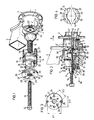
- the bearing cylinder 1 of a motor vehicle steering knuckle 2 with a wheel flange hub 3 is also shown.
- the wheel flange hub 3 has a cylindrical, hollow spline hub 4 which is pressed firmly into a roller bearing 5 serving as a wheel bearing and is to be pressed out with the aid of the device according to the invention in the direction of arrow 6 from this roller bearing 5, which at least initially remains in the bearing cylinder 1.
- the roller bearing 5 is pressed into the cylindrical bore 7 of the bearing cylinder 1 and secured against axial displacement by two retaining rings 10 seated in ring grooves 8 and 9.
- the pressure tool 11 which serves to press the wheel flange hub out of the roller bearing 5
- the securing ring 10 has already been removed from the annular groove 8 and is therefore not visible in FIGS. 1 and 2.
- the pressure tool 11 consists of two with respect to a common axis 12 diametrically or mirror image opposite, consisting of semi-cylindrical shell bodies consisting of spreading sectors 13 and 14, a support member 15, an expanding cone 16 with a hollow threaded spindle 17 with a nut thread 18 is provided, and a pressure spindle 19 and a pressure piece 20 which is arranged elastically on a cylindrical end projection 21 of the pressure spindle 19.
- the nut thread does not have to extend over the entire length of the threaded spindle 17.
- the two spreading sectors 13 and 14, which are of identical design, are each provided on their end faces facing the supporting member 15 with axial pins 22 and 23, respectively, which are arranged in pairs and have axial bores 24 and 25, respectively, of the same radius, of the pressure piece 15 designed as a cylindrical disk are.
- the diameter of the axial bores 24 and 25 are larger than the diameter of the axial pins 22 and 23, so that the expansion sectors 13 and 14, when the axial pins 22 and 23 are inserted in the axial bores 24 and 25, can also be pivoted in the radial direction. As can be seen from FIGS.
- the pressure piece has a total of three pairs of such axial bores, namely still the additional pairs of axial bores 26 and 27 or 28 and 29, which are each arranged symmetrically to the central axis or to the center of the disk-shaped support member 15 and whose distances R1 or R2 and R3 are of different sizes or are arranged in pairs on differently sized radii R1 / 2, R2 / 2 or R3 / 2.
- R1 or R2 and R3 are of different sizes or are arranged in pairs on differently sized radii R1 / 2, R2 / 2 or R3 / 2.
- the two expansion sectors 13, 14 have, on the end sections facing away from the support member 15, enlarged inner recesses 33 into which the expansion cone 16 can be freely inserted, while the remaining sections of the two Spreading sectors each have semicircular recesses 34 of smaller diameter, which each form spreading edges 35 at the transition to the larger recesses 33, which can be conical or rounded and against which the spreading cone 16 lies with its conical outer surface. It can be seen from FIG. 2 that the spreading edges 35 are at a certain axial distance from the drinking edges 13 'and 14' of the spreading sectors 13 and 14, respectively.
- This distance is chosen so that when the two expansion sectors 13 and 14 to the smallest possible diameter of a bearing bore 7 or an annular groove 8 are set, the expansion cone 16 does not protrude axially from the expansion sectors 13, 14 when the expansion sectors 13, 14 are inserted into the annular groove 8.
- the minimum distance must at least correspond to the expansion stroke of the expansion cone 16.
- the two expansion sectors 13 and 14 have radially outwardly projecting, rib-like anchoring projections 36 and 37 which, as can be seen from FIG. 2, can be inserted in a form-fitting manner in the annular groove 8 of the bearing cylinder 1.
- the expansion cone 16 is moved with the aid of the threaded spindle 17 relative to the two expansion sectors 13 and 14 in the direction of the arrow 38, so that the two expansion sectors 13 and 14 are axially anchored in the annular groove 8 results. Thereafter, it is only necessary to turn the pressure spindle 19 by attaching a rotary key to the hexagon key head 32 so that an axial movement occurs in the direction of arrow 6, through which the pressure piece 20, which is located on the bore of the spline hub 4 provided with splines 4 ′ can center itself, pushes the wheel flange hub 3 out of the roller bearing 5, which is still secured against axial displacement by the locking ring 10.
- a helical spring 39 is provided, which is joined into a ring and is guided in outer annular grooves 40 of the two expansion sectors 13 and 14.
- the annular groove 8 of the bearing cylinder 1, in which the rib-like anchoring projections 36 and 37 of the two expansion sectors 13 and 14 are anchored, is in the immediate vicinity of the end face of the roller bearing 5 or the spline hub 4, it is necessary for the pressure piece 20 within the axial length of the two expansion sectors 13 and 14 to provide a space in which the pressure piece 20 can be sunk in the axial direction when the two expansion sectors 13 and 14 are fastened in the annular groove 8.
- the two recesses 33 are sufficient to be able to insert the pressure piece 20 axially deep enough into the two ring sectors 13 and 14.
Landscapes
- Engineering & Computer Science (AREA)
- Mechanical Engineering (AREA)
- Rolling Contact Bearings (AREA)
- Mounting Of Bearings Or Others (AREA)
- Hand Tools For Fitting Together And Separating, Or Other Hand Tools (AREA)
- Arrangement Or Mounting Of Propulsion Units For Vehicles (AREA)
- Glass Compositions (AREA)
- Lining And Supports For Tunnels (AREA)
Priority Applications (1)
| Application Number | Priority Date | Filing Date | Title |
|---|---|---|---|
| AT86108835T ATE48390T1 (de) | 1985-08-28 | 1986-06-28 | Vorrichtung zum herausdruecken von radflanschnaben oder flanschkeilnaben von kraftfahrzeugen od. dgl. aus einem wellenlager. |
Applications Claiming Priority (2)
| Application Number | Priority Date | Filing Date | Title |
|---|---|---|---|
| DE3530726A DE3530726C1 (de) | 1985-08-28 | 1985-08-28 | Vorrichtung zum Herausdruecken von Radflanschnaben oder Flanschkeilnaben von Kraftfahrzeugen od.dgl. aus einem Wellenlager |
| DE3530726 | 1985-08-28 |
Publications (2)
| Publication Number | Publication Date |
|---|---|
| EP0215207A1 true EP0215207A1 (fr) | 1987-03-25 |
| EP0215207B1 EP0215207B1 (fr) | 1989-12-06 |
Family
ID=6279572
Family Applications (1)
| Application Number | Title | Priority Date | Filing Date |
|---|---|---|---|
| EP86108835A Expired EP0215207B1 (fr) | 1985-08-28 | 1986-06-28 | Dispositif pour faire sortir des moyeux de bride de roue ou des moyeux cannelés de bride de véhicules à moteur ou similaires d'un palier d'arbre |
Country Status (9)
| Country | Link |
|---|---|
| US (1) | US4682395A (fr) |
| EP (1) | EP0215207B1 (fr) |
| JP (1) | JPS6248467A (fr) |
| AT (1) | ATE48390T1 (fr) |
| AU (1) | AU579488B2 (fr) |
| CA (1) | CA1256680A (fr) |
| DE (1) | DE3530726C1 (fr) |
| DK (1) | DK157235C (fr) |
| ES (1) | ES295326Y (fr) |
Families Citing this family (22)
| Publication number | Priority date | Publication date | Assignee | Title |
|---|---|---|---|---|
| DE3730017C1 (de) * | 1987-09-08 | 1989-01-26 | Horst Klann | Vorrichtung zum Einpressen und Abziehen von Lagern oder Huelsen,insbesondere fuer Achslager und/oder Radflanschnaben an Kraftfahrzeugen |
| US4896412A (en) * | 1989-02-27 | 1990-01-30 | Brunswick Corporation | Assembly tool for marine drive lower gearcase |
| US4977661A (en) * | 1989-08-07 | 1990-12-18 | Wood Thomas H | Carrier bearing and axle bearing puller |
| US5131129A (en) * | 1991-08-27 | 1992-07-21 | Caterpillar Inc. | Tool assembly |
| US5210919A (en) * | 1992-04-27 | 1993-05-18 | Caterpillar Inc. | Tool assembly |
| CA72334S (fr) | 1992-06-29 | 1993-03-25 | Michel Caron | Arrche moyeu pousse cardan |
| USD358075S (en) | 1994-01-13 | 1995-05-09 | Ulmer Peter F | Mechanical fan blade puller |
| DE29715780U1 (de) * | 1997-09-03 | 1999-01-07 | Arends, Berend, 26736 Krummhörn | Abziehvorrichtung, vorzugsweise für Radlager von Kraftfahrzeugen |
| US5991994A (en) * | 1998-02-03 | 1999-11-30 | Chrysler Corporation | Bearing removal tool for a wheel hub |
| DE10018799A1 (de) * | 2000-04-15 | 2001-10-25 | Volkswagen Ag | Montagevorrichtung für die Montage einer Radlagernabeneinheit an einem Radträger eines Kraftfahrzeuges |
| USD452121S1 (en) | 2000-05-30 | 2001-12-18 | Emery C. Teichelman | Tool for removing a sewer pop-up valve cap |
| US6539601B1 (en) | 2002-06-10 | 2003-04-01 | Floyd E. Cloward | Bearing press |
| US6886227B1 (en) | 2003-03-13 | 2005-05-03 | Terry L. Hedrick | Low impact shaft remover |
| DE102005011806B4 (de) * | 2004-03-20 | 2008-10-02 | Klann-Spezial-Werkzeugbau-Gmbh | Flexible Auspressvorrichtung für Dämpfungsbuchsen einer Kraftfahrzeugachse |
| DE202005008241U1 (de) * | 2005-05-23 | 2005-07-21 | Klann-Spezial-Werkzeugbau-Gmbh | Werkzeugsystem zum Austauschen einer Glühkerze eines Dieselmotors |
| USD594718S1 (en) * | 2008-04-21 | 2009-06-23 | Glen Robert Duffy | Axle bearing press tool |
| DE102010052122A1 (de) * | 2010-11-22 | 2012-05-24 | Tracto-Technik Gmbh & Co. Kg | Vorrichtung zum Abziehen einer auf einer Radnabe eines Kraftfahrzeugs sitzenden Felge |
| CN104842146A (zh) * | 2015-05-22 | 2015-08-19 | 泉州市汉威机械制造有限公司 | 一种模轮轮毂拆卸方法 |
| CN106323739A (zh) * | 2016-09-28 | 2017-01-11 | 重庆圣巴巴拉实业有限公司 | 一种回转弯曲试验机轮毂退出装置 |
| TWM578743U (zh) * | 2018-08-01 | 2019-06-01 | 蘭陽水漾科技股份有限公司 | 馬達汲水之改良裝置 |
| USD931698S1 (en) * | 2020-01-30 | 2021-09-28 | G & G Technics Pty Ltd | Harmonic balancer puller |
| CN117086619B (zh) * | 2023-07-18 | 2025-09-16 | 江苏阳铭互联智能系统有限公司 | 制动器装配机及其装配工艺 |
Citations (5)
| Publication number | Priority date | Publication date | Assignee | Title |
|---|---|---|---|---|
| DE427850C (de) * | 1924-11-25 | 1926-04-15 | Johann Engeln | Abzugvorrichtung fuer das Antriebsritzel von Elektromotoren |
| FR996992A (fr) * | 1949-10-06 | 1951-12-31 | Dispositif pour moleter à la main une cage de roulement à billes ou tout organe analogue | |
| DE894830C (de) * | 1944-10-08 | 1953-10-29 | Maybach Motorenbau G M B H | Abziehvorrichtung, insbesondere fuer Waelzlager bei Brennkraftmaschinen und Kraftfahrzeugen |
| DE1035069B (de) * | 1953-08-20 | 1958-07-24 | Kleinbongartz & Kaiser | Zweischenkliger Innenauszieher fuer Kugellager u. dgl. |
| US3611540A (en) * | 1969-07-28 | 1971-10-12 | Us Air Force | Seal puller |
Family Cites Families (10)
| Publication number | Priority date | Publication date | Assignee | Title |
|---|---|---|---|---|
| FR959338A (fr) * | 1950-03-29 | |||
| GB191518076A (en) * | 1915-12-28 | 1916-06-01 | Ebenezer George Cross | A New or Improved Device for Extracting Ball Bearing Races, Valve Seats, and the like from their Pockets or Housings. |
| US2031998A (en) * | 1934-07-24 | 1936-02-25 | Bliss Louis Vencil | Bearing pulling tool |
| US2170461A (en) * | 1937-06-23 | 1939-08-22 | Pepperdine Ben | Combination puller |
| DE875329C (de) * | 1943-03-05 | 1953-04-30 | Hans Oesch | Abziehvorrichtung, insbesondere zum Ausziehen und Abziehen von Lagerringen, Zahnkraenzen u. dgl. |
| US2376721A (en) * | 1944-07-28 | 1945-05-22 | Charles J Piper | Pulling tool |
| US2835029A (en) * | 1953-06-17 | 1958-05-20 | Sr James F Collins | Pulling tool |
| US2971254A (en) * | 1957-04-04 | 1961-02-14 | Burton C Fairfield | Pilot bearing race puller |
| US4288900A (en) * | 1980-05-27 | 1981-09-15 | Fmc Corporation | Puller tool |
| DE8434762U1 (de) * | 1984-11-23 | 1985-03-14 | Kroselj, Franc, 1000 Berlin | Vorrichtung zum aus- und einbauen von waelzlagern |
-
1985
- 1985-08-28 DE DE3530726A patent/DE3530726C1/de not_active Expired
-
1986
- 1986-06-25 ES ES1986295326U patent/ES295326Y/es not_active Expired
- 1986-06-28 EP EP86108835A patent/EP0215207B1/fr not_active Expired
- 1986-06-28 AT AT86108835T patent/ATE48390T1/de active
- 1986-08-01 US US06/892,483 patent/US4682395A/en not_active Expired - Fee Related
- 1986-08-26 DK DK405086A patent/DK157235C/da not_active IP Right Cessation
- 1986-08-27 CA CA000516965A patent/CA1256680A/fr not_active Expired
- 1986-08-27 AU AU61890/86A patent/AU579488B2/en not_active Ceased
- 1986-08-28 JP JP61200257A patent/JPS6248467A/ja active Granted
Patent Citations (5)
| Publication number | Priority date | Publication date | Assignee | Title |
|---|---|---|---|---|
| DE427850C (de) * | 1924-11-25 | 1926-04-15 | Johann Engeln | Abzugvorrichtung fuer das Antriebsritzel von Elektromotoren |
| DE894830C (de) * | 1944-10-08 | 1953-10-29 | Maybach Motorenbau G M B H | Abziehvorrichtung, insbesondere fuer Waelzlager bei Brennkraftmaschinen und Kraftfahrzeugen |
| FR996992A (fr) * | 1949-10-06 | 1951-12-31 | Dispositif pour moleter à la main une cage de roulement à billes ou tout organe analogue | |
| DE1035069B (de) * | 1953-08-20 | 1958-07-24 | Kleinbongartz & Kaiser | Zweischenkliger Innenauszieher fuer Kugellager u. dgl. |
| US3611540A (en) * | 1969-07-28 | 1971-10-12 | Us Air Force | Seal puller |
Also Published As
| Publication number | Publication date |
|---|---|
| DK405086D0 (da) | 1986-08-26 |
| DE3530726C1 (de) | 1986-09-18 |
| CA1256680A (fr) | 1989-07-04 |
| DK405086A (da) | 1987-03-01 |
| ES295326U (es) | 1986-12-01 |
| ES295326Y (es) | 1987-08-01 |
| ATE48390T1 (de) | 1989-12-15 |
| DK157235C (da) | 1990-05-28 |
| JPS6248467A (ja) | 1987-03-03 |
| US4682395A (en) | 1987-07-28 |
| JPH0217307B2 (fr) | 1990-04-20 |
| AU6189086A (en) | 1987-03-05 |
| AU579488B2 (en) | 1988-11-24 |
| EP0215207B1 (fr) | 1989-12-06 |
| DK157235B (da) | 1989-11-27 |
Similar Documents
| Publication | Publication Date | Title |
|---|---|---|
| EP0215207B1 (fr) | Dispositif pour faire sortir des moyeux de bride de roue ou des moyeux cannelés de bride de véhicules à moteur ou similaires d'un palier d'arbre | |
| DE3314591C2 (fr) | ||
| EP0306738B1 (fr) | Dispositif pour emmancher et retirer des paliers ou manchons, surtout pour paliers d'arbre et/ou moyeux de boudin de roue de véhicules à moteur | |
| EP0512498B1 (fr) | Outil pour ôter un palier d'un axe | |
| EP0216030A1 (fr) | Dispositif pour emmancher et retirer des paliers ou manchons, surtout pour paliers d'arbre et/ou moyeux de boudin de roue de véhicules à moteur | |
| EP0879379B1 (fr) | Systeme de fixation | |
| EP1635159A2 (fr) | Dispositif de fixation rapide avec moyen de centrage d'une roue de véhicule sur une broche d'une machine d'équilibrage. | |
| EP0790423A1 (fr) | Méthode de fabrication d'un dispositif de connection pour des extrémités d'arbres cannelés destiné à la transmission d'un couple | |
| DE10315534B4 (de) | Spannhülse mit Mutter | |
| DE20206000U1 (de) | Vorrichtung zum Austauschen einer Radflanschnabe sowie eines Radlagers | |
| DE102012006700A1 (de) | Radlagerwerkzeug | |
| DE102005011806B4 (de) | Flexible Auspressvorrichtung für Dämpfungsbuchsen einer Kraftfahrzeugachse | |
| DE4205662C2 (de) | Zentriergerät | |
| DE10245235B4 (de) | Spannsatz | |
| DE3533019A1 (de) | Vorrichtung zum schleifen und/oder reparieren von ebenen, ringfoermigen flaechen | |
| DE102015005776B4 (de) | Einrichtung zum spielfreien Aufspannen eines Bauteils, insbesondere eines Werkzeugs, und Bauteil zur Verwendung in der Einrichtung | |
| EP0145795A1 (fr) | Roue pivotante à support amovible | |
| DE9315919U1 (de) | Universal Naben-Abzieh- und Montagevorrichtung | |
| DE2116818C3 (de) | Schraubenzieher | |
| DE8602006U1 (de) | Montagevorrichtung für konzentrisch zusammen zu fügende Bauteile, insbesondere für Scheibenkupplungen von Kraftfahrzeuggetrieben | |
| DE2344230A1 (de) | Vorrichtung zum lagern von wickelhuelsen | |
| DE9012194U1 (de) | Werkzeug zum Ausbauen und Einbauen von Lagern | |
| EP0776775A1 (fr) | Palier de roue | |
| EP0391228A2 (fr) | Dispositif de montage pour embrayages à disque de véhicule | |
| DE9111602U1 (de) | Vorrichtung zum Ein- und Auspressen von Silentlagern an Kraftfahrzeugachsen |
Legal Events
| Date | Code | Title | Description |
|---|---|---|---|
| PUAI | Public reference made under article 153(3) epc to a published international application that has entered the european phase |
Free format text: ORIGINAL CODE: 0009012 |
|
| AK | Designated contracting states |
Kind code of ref document: A1 Designated state(s): AT BE CH FR GB IT LI NL SE |
|
| 17P | Request for examination filed |
Effective date: 19870423 |
|
| 17Q | First examination report despatched |
Effective date: 19880601 |
|
| GRAA | (expected) grant |
Free format text: ORIGINAL CODE: 0009210 |
|
| AK | Designated contracting states |
Kind code of ref document: B1 Designated state(s): AT BE CH FR GB IT LI NL SE |
|
| REF | Corresponds to: |
Ref document number: 48390 Country of ref document: AT Date of ref document: 19891215 Kind code of ref document: T |
|
| ET | Fr: translation filed | ||
| GBT | Gb: translation of ep patent filed (gb section 77(6)(a)/1977) | ||
| ITF | It: translation for a ep patent filed | ||
| PLBE | No opposition filed within time limit |
Free format text: ORIGINAL CODE: 0009261 |
|
| STAA | Information on the status of an ep patent application or granted ep patent |
Free format text: STATUS: NO OPPOSITION FILED WITHIN TIME LIMIT |
|
| 26N | No opposition filed | ||
| PGFP | Annual fee paid to national office [announced via postgrant information from national office to epo] |
Ref country code: GB Payment date: 19910418 Year of fee payment: 6 |
|
| PGFP | Annual fee paid to national office [announced via postgrant information from national office to epo] |
Ref country code: SE Payment date: 19910426 Year of fee payment: 6 Ref country code: AT Payment date: 19910426 Year of fee payment: 6 |
|
| PGFP | Annual fee paid to national office [announced via postgrant information from national office to epo] |
Ref country code: BE Payment date: 19910508 Year of fee payment: 6 |
|
| PGFP | Annual fee paid to national office [announced via postgrant information from national office to epo] |
Ref country code: FR Payment date: 19910517 Year of fee payment: 6 |
|
| PGFP | Annual fee paid to national office [announced via postgrant information from national office to epo] |
Ref country code: CH Payment date: 19910617 Year of fee payment: 6 |
|
| ITTA | It: last paid annual fee | ||
| PGFP | Annual fee paid to national office [announced via postgrant information from national office to epo] |
Ref country code: NL Payment date: 19910630 Year of fee payment: 6 |
|
| PG25 | Lapsed in a contracting state [announced via postgrant information from national office to epo] |
Ref country code: GB Effective date: 19920628 Ref country code: AT Effective date: 19920628 |
|
| PG25 | Lapsed in a contracting state [announced via postgrant information from national office to epo] |
Ref country code: SE Effective date: 19920629 |
|
| PG25 | Lapsed in a contracting state [announced via postgrant information from national office to epo] |
Ref country code: LI Effective date: 19920630 Ref country code: CH Effective date: 19920630 Ref country code: BE Effective date: 19920630 |
|
| BERE | Be: lapsed |
Owner name: KLANN HORST Effective date: 19920630 |
|
| PG25 | Lapsed in a contracting state [announced via postgrant information from national office to epo] |
Ref country code: NL Effective date: 19930101 |
|
| NLV4 | Nl: lapsed or anulled due to non-payment of the annual fee | ||
| GBPC | Gb: european patent ceased through non-payment of renewal fee |
Effective date: 19920628 |
|
| PG25 | Lapsed in a contracting state [announced via postgrant information from national office to epo] |
Ref country code: FR Effective date: 19930226 |
|
| REG | Reference to a national code |
Ref country code: CH Ref legal event code: PL |
|
| REG | Reference to a national code |
Ref country code: FR Ref legal event code: ST |
|
| EUG | Se: european patent has lapsed |
Ref document number: 86108835.9 Effective date: 19930109 |
|
| PG25 | Lapsed in a contracting state [announced via postgrant information from national office to epo] |
Ref country code: IT Free format text: LAPSE BECAUSE OF NON-PAYMENT OF DUE FEES;WARNING: LAPSES OF ITALIAN PATENTS WITH EFFECTIVE DATE BEFORE 2007 MAY HAVE OCCURRED AT ANY TIME BEFORE 2007. THE CORRECT EFFECTIVE DATE MAY BE DIFFERENT FROM THE ONE RECORDED. Effective date: 20050628 |