EP0216309A1 - Automatic tool assembly apparatus - Google Patents
Automatic tool assembly apparatus Download PDFInfo
- Publication number
- EP0216309A1 EP0216309A1 EP86112870A EP86112870A EP0216309A1 EP 0216309 A1 EP0216309 A1 EP 0216309A1 EP 86112870 A EP86112870 A EP 86112870A EP 86112870 A EP86112870 A EP 86112870A EP 0216309 A1 EP0216309 A1 EP 0216309A1
- Authority
- EP
- European Patent Office
- Prior art keywords
- tool
- assembly
- module
- unit
- modules
- Prior art date
- Legal status (The legal status is an assumption and is not a legal conclusion. Google has not performed a legal analysis and makes no representation as to the accuracy of the status listed.)
- Granted
Links
Images





Classifications
-
- B—PERFORMING OPERATIONS; TRANSPORTING
- B23—MACHINE TOOLS; METAL-WORKING NOT OTHERWISE PROVIDED FOR
- B23Q—DETAILS, COMPONENTS, OR ACCESSORIES FOR MACHINE TOOLS, e.g. ARRANGEMENTS FOR COPYING OR CONTROLLING; MACHINE TOOLS IN GENERAL CHARACTERISED BY THE CONSTRUCTION OF PARTICULAR DETAILS OR COMPONENTS; COMBINATIONS OR ASSOCIATIONS OF METAL-WORKING MACHINES, NOT DIRECTED TO A PARTICULAR RESULT
- B23Q3/00—Devices holding, supporting, or positioning work or tools, of a kind normally removable from the machine
- B23Q3/155—Arrangements for automatic insertion or removal of tools, e.g. combined with manual handling
- B23Q3/157—Arrangements for automatic insertion or removal of tools, e.g. combined with manual handling of rotary tools
- B23Q3/15713—Arrangements for automatic insertion or removal of tools, e.g. combined with manual handling of rotary tools a transfer device taking a single tool from a storage device and inserting it in a spindle
- B23Q3/1572—Arrangements for automatic insertion or removal of tools, e.g. combined with manual handling of rotary tools a transfer device taking a single tool from a storage device and inserting it in a spindle the storage device comprising rotating or circulating storing means
- B23Q3/15722—Rotary discs or drums
-
- B—PERFORMING OPERATIONS; TRANSPORTING
- B23—MACHINE TOOLS; METAL-WORKING NOT OTHERWISE PROVIDED FOR
- B23B—TURNING; BORING
- B23B31/00—Chucks; Expansion mandrels; Adaptations thereof for remote control
- B23B31/006—Conical shanks of tools
-
- B—PERFORMING OPERATIONS; TRANSPORTING
- B23—MACHINE TOOLS; METAL-WORKING NOT OTHERWISE PROVIDED FOR
- B23B—TURNING; BORING
- B23B31/00—Chucks; Expansion mandrels; Adaptations thereof for remote control
- B23B31/02—Chucks
- B23B31/10—Chucks characterised by the retaining or gripping devices or their immediate operating means
- B23B31/113—Retention by bayonet connection
-
- B—PERFORMING OPERATIONS; TRANSPORTING
- B23—MACHINE TOOLS; METAL-WORKING NOT OTHERWISE PROVIDED FOR
- B23B—TURNING; BORING
- B23B31/00—Chucks; Expansion mandrels; Adaptations thereof for remote control
- B23B31/02—Chucks
- B23B31/24—Chucks characterised by features relating primarily to remote control of the gripping means
- B23B31/26—Chucks characterised by features relating primarily to remote control of the gripping means using mechanical transmission through the working-spindle
- B23B31/261—Chucks characterised by features relating primarily to remote control of the gripping means using mechanical transmission through the working-spindle clamping the end of the toolholder shank
- B23B31/265—Chucks characterised by features relating primarily to remote control of the gripping means using mechanical transmission through the working-spindle clamping the end of the toolholder shank by means of collets
-
- B—PERFORMING OPERATIONS; TRANSPORTING
- B23—MACHINE TOOLS; METAL-WORKING NOT OTHERWISE PROVIDED FOR
- B23Q—DETAILS, COMPONENTS, OR ACCESSORIES FOR MACHINE TOOLS, e.g. ARRANGEMENTS FOR COPYING OR CONTROLLING; MACHINE TOOLS IN GENERAL CHARACTERISED BY THE CONSTRUCTION OF PARTICULAR DETAILS OR COMPONENTS; COMBINATIONS OR ASSOCIATIONS OF METAL-WORKING MACHINES, NOT DIRECTED TO A PARTICULAR RESULT
- B23Q3/00—Devices holding, supporting, or positioning work or tools, of a kind normally removable from the machine
- B23Q3/155—Arrangements for automatic insertion or removal of tools, e.g. combined with manual handling
- B23Q3/15513—Arrangements for automatic insertion or removal of tools, e.g. combined with manual handling the tool being taken from a storage device and transferred to a tool holder by means of transfer devices
-
- B—PERFORMING OPERATIONS; TRANSPORTING
- B23—MACHINE TOOLS; METAL-WORKING NOT OTHERWISE PROVIDED FOR
- B23Q—DETAILS, COMPONENTS, OR ACCESSORIES FOR MACHINE TOOLS, e.g. ARRANGEMENTS FOR COPYING OR CONTROLLING; MACHINE TOOLS IN GENERAL CHARACTERISED BY THE CONSTRUCTION OF PARTICULAR DETAILS OR COMPONENTS; COMBINATIONS OR ASSOCIATIONS OF METAL-WORKING MACHINES, NOT DIRECTED TO A PARTICULAR RESULT
- B23Q3/00—Devices holding, supporting, or positioning work or tools, of a kind normally removable from the machine
- B23Q3/155—Arrangements for automatic insertion or removal of tools, e.g. combined with manual handling
- B23Q3/1552—Arrangements for automatic insertion or removal of tools, e.g. combined with manual handling parts of devices for automatically inserting or removing tools
- B23Q3/15553—Tensioning devices or tool holders, e.g. grippers
-
- Y—GENERAL TAGGING OF NEW TECHNOLOGICAL DEVELOPMENTS; GENERAL TAGGING OF CROSS-SECTIONAL TECHNOLOGIES SPANNING OVER SEVERAL SECTIONS OF THE IPC; TECHNICAL SUBJECTS COVERED BY FORMER USPC CROSS-REFERENCE ART COLLECTIONS [XRACs] AND DIGESTS
- Y10—TECHNICAL SUBJECTS COVERED BY FORMER USPC
- Y10T—TECHNICAL SUBJECTS COVERED BY FORMER US CLASSIFICATION
- Y10T29/00—Metal working
- Y10T29/51—Plural diverse manufacturing apparatus including means for metal shaping or assembling
- Y10T29/5104—Type of machine
- Y10T29/5105—Drill press
- Y10T29/5107—Drilling and other
-
- Y—GENERAL TAGGING OF NEW TECHNOLOGICAL DEVELOPMENTS; GENERAL TAGGING OF CROSS-SECTIONAL TECHNOLOGIES SPANNING OVER SEVERAL SECTIONS OF THE IPC; TECHNICAL SUBJECTS COVERED BY FORMER USPC CROSS-REFERENCE ART COLLECTIONS [XRACs] AND DIGESTS
- Y10—TECHNICAL SUBJECTS COVERED BY FORMER USPC
- Y10T—TECHNICAL SUBJECTS COVERED BY FORMER US CLASSIFICATION
- Y10T29/00—Metal working
- Y10T29/51—Plural diverse manufacturing apparatus including means for metal shaping or assembling
- Y10T29/5124—Plural diverse manufacturing apparatus including means for metal shaping or assembling with means to feed work intermittently from one tool station to another
-
- Y—GENERAL TAGGING OF NEW TECHNOLOGICAL DEVELOPMENTS; GENERAL TAGGING OF CROSS-SECTIONAL TECHNOLOGIES SPANNING OVER SEVERAL SECTIONS OF THE IPC; TECHNICAL SUBJECTS COVERED BY FORMER USPC CROSS-REFERENCE ART COLLECTIONS [XRACs] AND DIGESTS
- Y10—TECHNICAL SUBJECTS COVERED BY FORMER USPC
- Y10T—TECHNICAL SUBJECTS COVERED BY FORMER US CLASSIFICATION
- Y10T409/00—Gear cutting, milling, or planing
- Y10T409/30—Milling
- Y10T409/30952—Milling with cutter holder
-
- Y—GENERAL TAGGING OF NEW TECHNOLOGICAL DEVELOPMENTS; GENERAL TAGGING OF CROSS-SECTIONAL TECHNOLOGIES SPANNING OVER SEVERAL SECTIONS OF THE IPC; TECHNICAL SUBJECTS COVERED BY FORMER USPC CROSS-REFERENCE ART COLLECTIONS [XRACs] AND DIGESTS
- Y10—TECHNICAL SUBJECTS COVERED BY FORMER USPC
- Y10T—TECHNICAL SUBJECTS COVERED BY FORMER US CLASSIFICATION
- Y10T483/00—Tool changing
- Y10T483/18—Tool transfer to or from matrix
-
- Y—GENERAL TAGGING OF NEW TECHNOLOGICAL DEVELOPMENTS; GENERAL TAGGING OF CROSS-SECTIONAL TECHNOLOGIES SPANNING OVER SEVERAL SECTIONS OF THE IPC; TECHNICAL SUBJECTS COVERED BY FORMER USPC CROSS-REFERENCE ART COLLECTIONS [XRACs] AND DIGESTS
- Y10—TECHNICAL SUBJECTS COVERED BY FORMER USPC
- Y10T—TECHNICAL SUBJECTS COVERED BY FORMER US CLASSIFICATION
- Y10T483/00—Tool changing
- Y10T483/18—Tool transfer to or from matrix
- Y10T483/1864—Tool transfer to or from matrix including tool pot or adapter
Definitions
- the present invention relates to an automatic tool assembly apparatus for automatically assembling a predetermined tool required for a machine tool from respective modules of modular constituted tools which are divided and stored in units of modules and supplying it to the machine tool and, more particularly, to an automatic assembling apparatus of a modular constituted tool used in a machining center, an NC lathe, a turning center or the like.
- An automatic tool exchange apparatus which stores respective tools to be mounted on a machine tool in a tool housing conveys a tool designated in accordance with production control data from the tool housing and feeds the designated tool in the machine tool to automatically exchange tools for a machine tool is conventionally known.
- An assembly-type modular constituted tool replacing a conventional integral tool has also been developed.
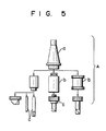
- Modular constituted tool A of this type has, as shown in Fig. 5, holder module a , adapter module b , and blade module c .
- Module b is mounted on module a
- module c is mounted on holder module b .
- Modular constituted tool A shown in Fig. 5 is assembled by mounting blade module c on module a directly or through module b . Only module c at the distal portion of tool A can be exchanged without exchanging all the components of tool A. Therefore, tool A is light-weight, easy to handle, and can reduce the space of the tool housing required for storing the tools.
- modular tool A is assembled and disassembled manually. More specifically, a plurality of modules a , b , and c are aligned and stocked in the tool housing. The assembly order of modular tool A is determined in accordance with the production control data. The operator picks a required one of respective modules from the tool stock rack of the tool housing, and performs assembling on an assembly table. Thus, many manual procedures are required in assembly and disassembly of tool A. In addition, when the number of modules is increased, an erroneous combination may occur.
- An automatic tool rack is known as a tool stocker for storing tools, wherein a plurality of tool holders are provided on an endless chain, and modules are stored in the tool holders and conveyed. In this case, however, modules are stored in and picked up from the respective tool holders manually by an operator.
- An automatic tool assembly apparatus has a tool stock unit for storing a plurality of types of modular constituted tools in a disassembled state in units of modules, a tool transfer unit for assembling a predetermined tool among a plurality of modules in the tool stock unit, and transferring and feeding the assembled tool from the tool stock unit, and a control unit.
- the tool stock unit has a first stock unit for holding a rotating tool as a module constituted tool in a state disassembled in units of respective modules.
- a stock position of a required module corresponding to a tool required by a machine tool is indexed from a signal supplied from the control unit.
- the required modules are sequentially positioned at a tool assembly position.
- the tool transfer unit has an assembly head movable in a direction to approach and separate from the tool assembly position by an instruction from the control unit.
- the assembly head clamps the modules positioned at the tool assembly position in response to the signal supplied from the control unit, removes the clamped modules from the tool stock unit, and sequentially assembles the clamped modules on a module positioned at another assembly position, thereby preparing a predetermined modular constituted tool.
- the assembled modular constituted tool is transferred out by a tool transfer unit.
- An automatic tool assembly apparatus has a magazine for storing a plurality of blade modules for a modular constituted tool consisting of a holder module and a blade module in an aligned state, and a pivotal arm which is pivotal between a blade module exchange position and an assembly position.
- the pivotal arm has, on an end thereof, a chuck capable of holding the blade module stored in the magazine at the exchange position, and, on the other end thereof, a coupling mechanism for assembling the blade module, which is held at the assembly position by the chuck and transferred, to a holder module.
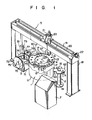
- Figs. l to 4 show an automatic assembly/feed apparatus of a modular constituted tool according to a first embodiment of the present invention.
- reference numeral l denotes a tool stock unit; 2, a tool stocker provided adjacent to stock unit l; 3, an assembly unit for a stationary tool such as a drilling tool; 5, a tool transfer unit; and 7, a control unit.
- Assembly head 6 is provided on transfer unit 5 to be reciprocal and vertically movable in order to feed a tool from stock unit l to tool stocker 2.
- Tool stock unit l will be described.
- Unit l has cylindrical main body ll.
- Turntable l2 is provided on main body ll and is rotated clockwise and counterclockwise by a drive mechanism (not shown).
- Turntable l2 is provided on main body ll and is rotated clockwise and counterclockwise by a drive mechanism (not shown).
- Turntable l2 has a circular shape.
- a plurality of through holes are formed in the outer peripheral portion of turntable l2 at equal angular intervals, and define tool holders l3.
- Holder module a , adapter module b , and blade module c which constitute modular tool A are held by holder l3 such that their axes are aligned in the vertical direction.
- a plurality of tool holders 4 for a large tool that are defined by circular notches are provided on the inner peripheral portion of turntable l2 at equal angular intervals.
- An annular groove formed at a proximal end portion of large tool A' is inserted in holder l4 in the transverse direction and is held thereat. Therefore, each module and large tool A' are arranged to be perpendicular to turntable l2 with their distal ends facing downward.
- Each module is selectively positioned at assembly position l7 by a means to be described later. Two positions l7 are provided on line l5 passing rotation center l2a of turntable l2.
- Tool transfer unit 5 is supported by frames l8 at its two ends, and has guide rod l9 and screw rod 20 extending above stock unit l in the transverse direction, and movable base 2l guided by guide rod l9 and engaged with screw rod 20.
- Rod 20 is driven by servo motor 22 to rotate.
- Base 2l has movable table 23 which is vertically movable with respect to assembly position l7.
- Assembly head 6 is mounted on table 23.
- head 6 is vertically moved by table 23 to approach and separate from position l7, and can travel along line l5 passing rotation center l2a of turntable l2 by means of rod 20.
- head 6 has a function to hold and assemble modules a , b , and c held by holder l3. More specifically, tool holding member 24 is provided and rotating drum 27 is rotatably supported in holding member main body 25 thereof through bearing 26. Tapered hole 28 is formed at a lower portion of drum 27.
- Draw bar 30 having collet chuck 29 is provided at a bottom portion of hole 28.
- Draw bar 30 is linked to piston 32 of hydraulic cylinder 3l provided on drum 27 and is biased in a contracting direction by Belleville spring 33.
- drive mechanism 34 drives drum 27.
- Module a of tool A is mounted in hole 28.
- Nut runner 37 is provided on the side wall of main body 25 through bracket 36.
- Runner 37 is constituted by drive motor 38, gear mechanism 39, and clamp shaft 40. Shaft 40 is urged against a clamp bolt of tool A by air cylinder 4l.
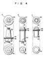
- tool A has petal-like engaging pawls 53 and 54 at an upper and lower ends, respectively, of tapered portion 52 of its module a .
- Engaging hole 57 engageable with pawl 54 is provided on the upper end of module b
- engaging pawl 58 projects from the lower end thereof.
- Engaging hole 59 selectively engageable with either pawl 54 or 58 is formed on the upper end of module c
- blade 60 is provided at a lower end thereof.
- Module a can be coupled to module c through module b , or directly to module c .
- flange 56 having annular groove 55 is provided on the outer peripheral surface of module a or c , so that groove 55 formed in flange 56 of either module is engaged with and supported by notch l5 of holder l3.
- clamp bolt 6l clamps engaging portions of modules b and a , and of modules a and c .
- Tapered portion 52 of module a of tool A arranged in the above manner is mounted in tapered hole 28 formed in drum of member 24.
- Pawl 53 is engaged with collet chuck 29. More specifically, chuck 29 is opened/closed by forward/backward movement of draw bar 30.
- piston 32 is moved forward by a hydraulic pressure supplied by hydraulic cylinder 3l
- chuck 29 is opened and released from pawl 53.
- draw bar 30 is moved backward by a restoring force of spring 33 in order to close chuck 29 and thus to clamp pawl 53.
- Tool stocker 2 shown in a right-hand portion of Fig. l is provided on line l6 extending from straight line l5 passing rotation center l2a of turntable l2.
- Stocker 2 has intermittently rotatable disk 62 on the upper end of support column 64.
- a plurality of tool holding members 63 are provided on the outer peripheral portion of disk 62.
- Each member 63 is defined by an arcuated notch in the same manner as holder l3, and vertically supports tool A therein.
- Unit 3 for turning tool as a stationary tool shown in the left-hand portion of Fig.l will now be described.
- Unit 3 is used for assembling a modular constituted tool used in a machine tool such as an NC vertical lathe.
- Reference numeral 7l denotes a main body of unit 3. Magazine 72 and movable table 73 are provided on one and the other sides on main body 7l. Pivotal arm 74 is provided between magazine 72 and table 73.
- Magazine 72 has disk 75 rotatable clockwise and counterclockwise, and a plurality of tool stock sections 76 provided at equal angular intervals on the outer peripheral portion of disk 75. Blade module d constituting modular constituted tool B is detachably inserted in each section 76.
- Table 73 has first and second holder sections 77 and 78. Sections 77 and 78 hold holder modules e for modular constituted tool B. Table 73 is reciprocal on main body 7l. In a neutral state, first holder section 77 opposes assembly position 79 and second holder section 78 opposes exchange position 80. When table 73 moves forward, section 77 opposes exchange position 80. When table 73 moves backward, section 78 opposes position 79.
- Coupling mechanism 8l comprises a nut runner opposes position 79.
- tool B is clamped by assembly head 6 of tool transfer unit 5 and is conveyed to a predetermined position of stocker 2.
- assembled modular tool B can be directly supplied to a machine tool, such as an NC lathe, by a tool transfer unit (not shown) such as a robot.
- Position 79 can be provided on a tool mounting section of a machine tool.
- a tool number code is designated in control unit 7 based on production control data, and a program indicating, e.g., a combination of tools required for machining is loaded (step Sl).
- the designated tool is tool A used in a machining center
- the type of tool is determined by unit 7, and a tool designation signal is input from unit 7 to tool stock unit l (steps S2 and S3).
- turntable l2 of the tool stock unit is rotated to index the holder module stock position (steps S4 and S5), expect for a case wherein module a is already mounted on assembly head 6.
- Respective modules constituting designated tool A are positioned at adjacent assembly position l7 (step S6).
- step S7 After module a of tool A is positioned at position l7, head 6 is positioned and moved downward. Head 6 is moved downward by table 23, tapered portion 52 of module a is fitted in tapered hole 27 of tool holding member 24, engaging pawl 53 of module a is clamped by chuck 29, and module a is thus clamped (step S7). When module a is clamped in this manner, head 6 is moved upward by table 23. As a result, module a held by head 6 is removed from holder l3 from above.
- holder l3 holding module c supplied in accordance with data from control unit 7 is positioned at assembly position l7, and then a blade module stock position is indexed (step S8).
- table 23 is moved downward, and module a held by head 6 is aligned with module c vertically held by holder l3 on a straight line (step S9).
- pawl 54 of module a is engaged with hole 59 of module c , and modules a and c are coupled in the vertical direction. Then, module a is rotated by driving of motor 34 and is engaged with pawl 54.
- step Sl0 when air cylinder 4l is moved forward and urges clamp shaft 40 of nut runner 37, shaft 40 is engaged with clamp bolt 6l. In this state, when motor 38 is driven, shaft 40 is rotated through gear mechanism 39 and clamps bolt 6l, thereby completing assembly with tool A by modules a and c (step Sl0).
- step Sl2 head 6 is moved upward again to pull module c from holder l3, and transfers pulled module c to tool stocker 2 by rotation of screw rod 20 of transfer unit 5.
- the stock position within stocker 2 is indexed (steps Sl2 to Sl4).
- module c is conveyed directly to the machine tool, not through stocker 2, and mounted thereon (step Sl3).
- step Sll assembly is performed at the tool fitting section of the machine tool
- Stocker 2 has a plurality of tool support members 63 on its disk 62. When a tool is clamped, it is supported since annular groove 55 formed in module a is engaged with member 63 (step Sl5). Head 6 is then returned to the origin (step Sl6).
- tools A are sequentially assembled at two assembly positions l7 and supplied to stocker 2 by tool convey unit 5.
- Tools A temporarily stored in stocker 2 are fed to the tool machine in aacordance with the processing order (steps Sl7 to S20).
- tool A is constituted by coupling modules a and c .
- module c is coupled to module a through module b (steps S2l to S23). Since large tool A' is held by tool holder l4 having a notch formed in the inner peripheral portion of turntable l2, it cannot be picked up only by moving head 6 upward. In this case, as described above, head 6 must be moved downward to clamp module a . Then, table 23 is moved by unit 5 in the transverse direction along line l5, i.e., along a direction of the notch of holder l4 and tool A' is picked up, and then head 6 must be moved upward.
- Tool B assembled at position 79 is moved to exchange position 80 by table 73 (step S27).
- Tool B is held by assembly head 6 of tool transfer unit 5 (steps S28 and S29), and is conveyed to tool stocker 2 (step Sl2).
- tool B is directly conveyed to a machine tool such as an NC vertical lathe.
- an assembly position is provided on a line passing the rotation center of a turntable of a tool stock unit, so that two assembly positions can be provided.
- a designated module can be indexed at a high speed, and different modules can be held at different assembly positions by a single indexing.
- a unit for assembling and feeding tool B for a machine tool in which a tool is stationary is provided to a unit for automatically assembling and feeding tool A for a machine tool in which a tool is rotated.
- a stationary tool assemble unit is not necessarily required.
- the turntable constituting the tool stock unit has a circular shape, holds modules constituting a usual modular tool at its outer peripheral portion and a large size tool at its inner peripheral portion. However, it can hold blade and adapter modules at its outer peripheral portion and a holder module at its inner peripheral portion.
- the tool stock unit can be an endless chain.
- the tool to be stored in the tool stock unit can be an integral tool, or a modular constituted tool which is used often can be assembled in advance and be stored in the tool stock unit.
- the module is coupled to the vertically held holder module from above.
- the module can be coupled from below.
- Used modular constituted tool A fed from a machine tool is temporarily stored in tool stocker 2 (steps S30 to S32). At this time, tool A is disassembled at assembly position l7 in the assembly stop mode, and the respective modules are stored in tool holder l3 of tool stock unit l.
- a stock position of an unnecessary tool fed from the machine tool is indexed (step S34).
- Assembly head 6 of tool transfer unit 5 is positioned (step S35). Then, the tool is clamped by head 6 (step S36).
- the type of tool clamped by head 6 is determined by control unit 7 (steps S37 and S38).
- a blade module stock position of stock unit l is indexed (step S39).
- the clamped tool is then conveyed to the assembly position by transfer unit 5 (step S40) and is disassembled into the respective modules through the steps opposite to those for the above assembly steps (step S4l).
- the stock position of holder module a at stock unit l is then indexed (step S42).
- Positioned module a is unclamped (steps S43 and S44) and is stored in stock unit l. Assembly head 6 is returned to the origin (step S45) and the following steps are repeated.
- step S38 When it is determined in step S38 that the tool clamped by head 6 is an integral tool, the stock position for the integral tool in stock unit l is indexed, and the tool conveyed to the stock position is unclamped by head 6 (steps S46 to S48).
- step S37 When it is determined in step S37 that the tool clamped by head 6 is a stationary tool used in an NC lathe and the like, the tool is conveyed to movable table 73 by transfer unit 5, and head 6 unclamps the tool (steps S49 and S50).
- Table 73 indexes the tool assembly position (step S5l), and coupling mechanism 8l removes the blade module from the holder module (step S52).
- step S53 the stock position of the blade module is indexed by magazine 72 (step S53), the blade module is conveyed to the stock position by pivotal arm 74 and is held at a predetermined position (step S54).
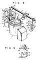
- the automatic tool assembly apparatus has a structure substantially the same as that of the first embodiment shown in Figs. l to 4.
- the same reference numerals in Figs. 8 and 9 denote the same or equivalent portions as in Figs. l to 4, and a detailed description thereof is omitted.
- tool stock unit l has cylindrical main body ll.
- Turntable l2 rotated clockwise and counterclockwise by a drive unit (not shown) is provided on main body ll.
- a plurality of tool holding members l3 are provided on the outer peripheral portion of turntable l2.
- Holder module a , adapter module b , and blade module c that constitute modular constituted tool A are held by member l3 such that their axes are aligned in the horizontal direction.
- each member l3 has L-shaped plate l4, and circular notch l5 is formed in the vertical wall of plate l4, as shown in Fig. 9.
- Each module is held such that its annular groove formed in its proximal end is fitted in notch l4 from above.
- modules are radially arranged on turntable l2 such that their distal ends are directed toward a central portion of turntable l2, and are then selectiveively positioned on assembly position l7 by a means to be described later.
- Tool transfer unit 5 has guide rod l9 having two ends supported by frames l8, screw rod 20 driven by servo motor 22, and movable base 2l guided by rod l9 and engaged with rod 20.
- Movable table 23 reciprocal with respect to assembly position l7 and pivotal between vertical and horizontal positions is provided on base 2l.
- Assembly head 6 is mounted on table 23. Therefore, head 6 is reciprocal with respect to position l7 upon movement of table 23, and can be directed in the horizontal or vertical direction.
- Head 6 can hold and assemble respective modules a , b , and c held by holder l3, and has an arrangement similar to that of the first embodiment shown in Fig. 3.
- Turning tool assembly unit 3 which assembles a tool used in a machine tool, such as an NC vertical lathe, is similar to the apparatus of the first embodiment.
- the similar portions of unit 3 as that of the first embodiment are denoted by the same reference numerals, and a detailed description therefor is omitted.
- assembled modular constituted tool B is fed to tool stocker 4 for a turning tool.
- Stocker 4 for the turning tool has the same arrangement as stocker 2 for the modular tool, and a detailed description thereof is omitted.
- the automatic assembly/feed apparatus shown in Figs. 8 and 9 assembles and disassembles a modular constituted tool in the same manner as the apparatus of the first embodiment shown in Figs. l to 4.
- Turntable l2 is then rotated again by a tool designation signal for blade module c supplied from control unit 7. Subsequently, holder l3 holding module c is positioned at assembly position l7. At this time, table 23 is pivoted downward so that module a held by head 6 is caused to oppose module c horizontally held by holder l3 along a straight line. In this state, head 6 is moved forward, engaging pawl 54 of module a is engaged with engaging hole 59 of module c , and module c is coupled to module a . In other words, modules a and c are assembled in the horizontal direction.
- Head 6 is moved backward by the movement of table 23 and is then pivoted downward.
- tool A held by head 6 is vertically set with its module c facing downward, and is fed to tool stocker 2 by tool transfer unit 5.
- turning tool assembly unit 3 When a designated tool is a tool used in an NC vertical lathe, turning tool assembly unit 3 is actuated in a similar manner to that in the first embodiment.
- modular constituted tool B assembled at assemble position 79 is moved to exchange position 80 by the movement of movable table 73, is held by assembly head 6, and is supplied to tool stocker 2 for a turning tool by tool transfer unit 5.
- Tool B supported by stocker 2 is conveyed to a machine tool such as an NC vertical lathe.
- respective automatic tool assembly units can hold holder, adapted, and blade modules constituting a modular constituted tool by a tool holder of a tool stock unit, automatically and sequentially position the designated modules at assembly positions, and automatically assembly the respective modules by the assembly head.
- operability and safety can be greatly improved compared to the conventional manual assembly.
- the attaching/detaching operation of the modules is performed in a uniaxial direction, i.e., vertically. Since the tool transfer unit is moved in another uniaxial direction, the modules can be assembled by the operation in a total of two axial directions and be supplied to the machine tool, thus achieving simplification of the entire apparatus and control.
- the respective modules When the respective modules are horizontally held by the tool holders, they can be attached/detached at a constant stroke irrespective of the length of each module, thus achieving simplification of the control of the movement stroke of the assembly head.
- Figs. l0 and ll show an overal configuration of the automatic tool assembly apparatus for a turning tool, such as a lathe. This apparatus can be used in combination with the automatic tool assembly apparatus shown in Figs. l to 4 and 8 and 9.
- reference numeral 3 denotes a main body. Magazine 72 is provided on one side of main body 3. Magazine 72 comprises reversible disk 75, a plurality of tool holding sections 76 provided at the same angular intervals on the outer peripheral surface of disk 75, and motor 48 for driving disk 75. A plurality of blade modules a of different types which constitute modular constituted tool B are detachably inserted in section 76.
- Assembly position 79 serving also as a disassembly position for tool B is provided to the other side of main body 3.
- holding mechanism 42 for holding holder module b of tool B is provided at position 79.
- Position 79 can be provided to the mount section of the machine tool.
- Reference numerals 42a denote a pair of support bases.
- Bearings 42b are provided to bases 42a.
- Rotating shafts 43a and 43b are rotatably provided to bearings 42b.
- Support frames 44a and 44b are fixed to shafts 43a and 43b.
- Clamp mechanism 45 for clamping module b in the radial direction is provided to frames 44a and 44b.
- Mechanism 45 can be rotated through 90° by drive motor 48 linked with shaft 43a and can be directed in the horizontal or vertical direction while clamping module b .
- module b comprises tapered portion 52 mounted on the mount base of the blade module of the machine tool, and holder section 50 detachably fixed on portion 52.
- Annular groove 55 is formed in portion 52.
- Mechanism 45 holds module b by clamping groove 55.
- Blade module reception base 95 is provided on the front face of holder section 50.
- Section 50 located on base 95 has draw bar 96 which is capable of moving forward and backward.
- the proximal portion of draw bar 96 is slidably inserted in guide hole 97 formed in section 50.
- Square tapered hole 96 is formed in the proximal portion of draw bar 96.
- Engaging portion l0l engageable with key groove l00 is formed in tapered surface 99 of hole 98 in the vertical direction.
- Slider l02 having a tapered surface coinciding with surface 99 is inserted in hole 98 to be vertically movable.
- Screw hole l03 is vertically formed in slider l02.
- Drive screw l04 inserted from an upper portion of holder 50 is screwed in hole l03.
- pivotal arm 74 is provided between magazine 72 and assembly position 79 on main body 3.
- Arm 74 is pivoted through l80° by rotation drive mechanism 49, such as a rotary actuator, having brake 49a, and is vertically moved by air cylinder 77.
- Chuck 78a which is opened/closed by rotary actuator 78 is provided at one end of arm 74.
- Nut runner 8l serving as a coupling mechanism is provided to the other end of arm 74.
- Chuck 78a has pawl sections 76a for clamping module a stored in stock section 76 of magazine 72 from two sides, so that it can mount and remove module a on and from section 76.
- Nut runner 8l has an arrangement as shown in Fig. l7.
- motor 82 is fixed to pivotal arm 74 through bracket 83.
- Drive gear 85 is fitted around rotating shaft 84 of motor 82.
- Gear housing 86 which is stationary with respect to bracket 83 is provided next to gear 85.
- Rotating cylinder 88 is rotatably supported in housing 86 through oil-impregnated bearing 87.
- Driven gear 89 engaged with drive gear 85 is provided on the outer surface of cylinder 88.
- Spline groove 90 is formed in the inner surface of cylinder 88.
- Spline shaft 9l is inserted in groove 90 to be vertically movable.
- Shaft 9l is biased downward by spring 92.
- Clamp shaft 93 is mounted on the lower end portion of shaft 9l, and clamps or releases drive screw l04 provided on holder section 50 of module b .
- the automatic tool assembly apparatus for a stationary tool which has the above-mentioned arrangement is provided adjacent to, e.g., apparatus 45 for a rotatting tool, as shown in Fig. l8.
- the apparatus selectively conveys stationary and rotating tools to tool stocker 2 by tool holding member 23 provided on tool transfer unit 5 connecting the same with apparatus 45, and conveys the tool from disk 62 of stocker 2 to a machine tool (not shown) through a transfer robot or the like.
- These components used for conveyance can be controlled by control unit 7.
- Processing order for machining is determined based on the production control data and tools required for the machining. Then, a tool designation signal is input from control unit 7 to the automatic tool assembly apparatus.
- the designated tool is, e.g., a stationary tool used in an NC lathe
- disk 74 of magazine 72 is rotated by motor 48, and tool holding section 76 which stores designated blade module a is positioned and stopped at exchange position 76a.
- holder module b which is fed by tool holding member 23 of tool transfer unit 5 is clamped by clamp mechanism 45 provided at assembly position 79, and is held horizontally.
- pivotal arm 74 located at an upper position by air cylinder 77 is pivoted by rotating drive mechanism 49, and chuck 76a at one end side thereof opposes blade module a positioned at exchange position 76a.
- arm 74 When assembly of tool B is completed, arm 74 is moved upward, pivoted through 90°, and is held in a neutral state.
- motor 46 When runner 8l is moved from assembly position 79 by the pivotal movement of arm 74, motor 46 is actuated to pivot support frames 44a and 44b through shaft 43a.
- clamp mechanism 45 When clamp mechanism 45 is pivoted through 90°, tool B is switched to be vertically oriented with tapered portion 52 of module b thereof facing upward.
- tool transfer unit 5 When tool B waits at assembly position 79, tool transfer unit 5 is actuated and holds tapered portion 52 of tool B with its tool holding member 23. Then, tool B is conveyed from stocker 2 to position 79 of the automatic tool assembly apparatus by tool transfer unit 5.
- used tool B is vertically clamped by mechanism 45 of hold mechanism 42 and is switched to be oriented in the horizontal direction.
- arm 74 is pivoted to cause runner 8l to oppose mechanism 42.
- drive screw l04 provided to the holder section l3 of module b is rotated counterclockwise by clamp shaft 93 of runner 8l.
- draw bar 96 is projected, and the engagement of draw bar 96 with engaging recess 95 of module a is canceled.
- a chuck and a nut runner are provided to one and the other ends, respectively, of its pivotal arm. Therefore, the holder and blade modules can be chucked by a chuck using a nut runner, and a loss time required for selecting and picking up a blade module can be eliminated.
- Two pivotal arms can be arranged to intersect with each other as needed.
- the automatic tool assembly apparatus can automatically and efficiently assemble and disassemble a blade module with respect to a holder module constituting a modular constituted tool. Also, since only the blade module is stored in a compact magazine, the entire appa ratus can be made small. Furthermore, the automatic tool assembly apparatus can be linked with a machine tool through a tool convey unit and can be systematized, thus allowing unmanned operation.
Landscapes
- Engineering & Computer Science (AREA)
- Mechanical Engineering (AREA)
- Automatic Tool Replacement In Machine Tools (AREA)
Abstract
Description
- The present invention relates to an automatic tool assembly apparatus for automatically assembling a predetermined tool required for a machine tool from respective modules of modular constituted tools which are divided and stored in units of modules and supplying it to the machine tool and, more particularly, to an automatic assembling apparatus of a modular constituted tool used in a machining center, an NC lathe, a turning center or the like.
- An automatic tool exchange apparatus which stores respective tools to be mounted on a machine tool in a tool housing conveys a tool designated in accordance with production control data from the tool housing and feeds the designated tool in the machine tool to automatically exchange tools for a machine tool is conventionally known. An assembly-type modular constituted tool replacing a conventional integral tool has also been developed. Modular constituted tool A of this type has, as shown in Fig. 5, holder module a, adapter module b, and blade module c. Module b is mounted on module a, and module c is mounted on holder module b. Modular constituted tool A shown in Fig. 5 is assembled by mounting blade module c on module a directly or through module b. Only module c at the distal portion of tool A can be exchanged without exchanging all the components of tool A. Therefore, tool A is light-weight, easy to handle, and can reduce the space of the tool housing required for storing the tools.
- Conventionally, however, modular tool A is assembled and disassembled manually. More specifically, a plurality of modules a, b, and c are aligned and stocked in the tool housing. The assembly order of modular tool A is determined in accordance with the production control data. The operator picks a required one of respective modules from the tool stock rack of the tool housing, and performs assembling on an assembly table. Thus, many manual procedures are required in assembly and disassembly of tool A. In addition, when the number of modules is increased, an erroneous combination may occur.
- An automatic tool rack is known as a tool stocker for storing tools, wherein a plurality of tool holders are provided on an endless chain, and modules are stored in the tool holders and conveyed. In this case, however, modules are stored in and picked up from the respective tool holders manually by an operator.
- It is an object of the present invention to provide an automatic tool assembly apparatus which can automatically assemble a modular constituted tool and can feed it to a machine tool.
- It is another object of the present invention to provide an automatic assembly/feed apparatus of a modular constituted tool, which can improve operability and safety, and can simplify a transfer unit for attaching/detaching a module on a tool stock unit and feeding a modular constituted tool.
- It is still another object of the present invention to provide an automatic assembly/feed apparatus of a modular constituted tool, whicn can automatically assemble a modular tool and feed it to respective machine tools, thereby improving operability and safety.
- An automatic tool assembly apparatus according to the present invention has a tool stock unit for storing a plurality of types of modular constituted tools in a disassembled state in units of modules, a tool transfer unit for assembling a predetermined tool among a plurality of modules in the tool stock unit, and transferring and feeding the assembled tool from the tool stock unit, and a control unit.
- The tool stock unit has a first stock unit for holding a rotating tool as a module constituted tool in a state disassembled in units of respective modules. In the first stock unit, a stock position of a required module corresponding to a tool required by a machine tool is indexed from a signal supplied from the control unit. Thus, the required modules are sequentially positioned at a tool assembly position. The tool transfer unit has an assembly head movable in a direction to approach and separate from the tool assembly position by an instruction from the control unit. The assembly head clamps the modules positioned at the tool assembly position in response to the signal supplied from the control unit, removes the clamped modules from the tool stock unit, and sequentially assembles the clamped modules on a module positioned at another assembly position, thereby preparing a predetermined modular constituted tool. The assembled modular constituted tool is transferred out by a tool transfer unit.
- An automatic tool assembly apparatus according to another aspect of the present invention has a magazine for storing a plurality of blade modules for a modular constituted tool consisting of a holder module and a blade module in an aligned state, and a pivotal arm which is pivotal between a blade module exchange position and an assembly position. The pivotal arm has, on an end thereof, a chuck capable of holding the blade module stored in the magazine at the exchange position, and, on the other end thereof, a coupling mechanism for assembling the blade module, which is held at the assembly position by the chuck and transferred, to a holder module.
- The other objects, features, and advantages of the present invention will be apparent from the detailed description hereinafter with reference to the accompanying drawings.
- This invention can be more fully understood from the following detailed description when taken in conjunction with the accompanying drawings, in which:
- Fig. l is a perspective view of an automatic tool assembly apparatus according to an embodiment of the present invention;
- Fig. 2 is a perspective view of a tool holder shown in Fig. l;
- Fig. 3 is a vertical sectional view of an assembly head shown in Fig. l;
- Fig. 4 shows plan, front, and bottom views, respectively, of a modular constituted tool in a disassembled state;
- Fig. 5 shows a typical modular constituted tool disassembled in units of modules;
- Figs. 6A and 6B are flow charts of a basic operation state when a tool is assembled by the automatic tool assembly apparatus shown in Fig. l, the flow charts including steps performed for some particular forms of application;
- Fig. 7A and 7B are flow charts of a basic operation state when a tool is disassembled and stored by the automatic tool assembly apparatus shown in Fig. l;
- Fig. 8 is an overall perspective view of an automatic tool assembly apparatus according a second embodiment of the present invention which is different from the embodiment shown in Fig. l;
- Fig. 9 is a perspective view of a tool holder of the tool stock unit of the apparatus shown in Fig. 8;
- Fig. l0 is a plan view of an automatic tool assembly apparatus according to another invention;
- Fig. ll is a side view of Fig. l0;
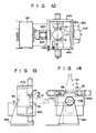
- Fig. l2 is a plan view of a holding mechanism of the automatic tool assembly apparatus shown in Fig. l0;
- Fig. l3 is a side view of the holding mechanism horizontally holding a holder module;
- Fig. l4 is a view similar to Fig. l3 but in a state vertically holding the holder module;
- Fig. l5 is a plan view showing a relationship between the holder module and a blade module;
- Fig. l6 is a vertical sectional view of the respective modules shown in Fig. l5;
- Fig. l7 is a partially sectional side view of a coupling mechanism of the automatic tool assembly apparatus shown in Fig. l0; and
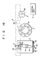
- Fig. l8 is a schematic diagram of an automatic tool assembly/transfer system seen from above.
- The embodiments of the present invention will be described with reference to the accompanying drawings.
- Figs. l to 4 show an automatic assembly/feed apparatus of a modular constituted tool according to a first embodiment of the present invention.
- Referring to Figs. l to 4, reference numeral l denotes a tool stock unit; 2, a tool stocker provided adjacent to stock unit l; 3, an assembly unit for a stationary tool such as a drilling tool; 5, a tool transfer unit; and 7, a control unit.
Assembly head 6 is provided ontransfer unit 5 to be reciprocal and vertically movable in order to feed a tool from stock unit l totool stocker 2. - Tool stock unit l will be described. Unit l has cylindrical main body ll. Turntable l2 is provided on main body ll and is rotated clockwise and counterclockwise by a drive mechanism (not shown). Turntable l2 is provided on main body ll and is rotated clockwise and counterclockwise by a drive mechanism (not shown). Turntable l2 has a circular shape. A plurality of through holes are formed in the outer peripheral portion of turntable l2 at equal angular intervals, and define tool holders l3. Holder module a, adapter module b, and blade module c which constitute modular tool A are held by holder l3 such that their axes are aligned in the vertical direction.
- As shown in Fig. 2, a plurality of
tool holders 4 for a large tool that are defined by circular notches are provided on the inner peripheral portion of turntable l2 at equal angular intervals. An annular groove formed at a proximal end portion of large tool A' is inserted in holder l4 in the transverse direction and is held thereat. Therefore, each module and large tool A' are arranged to be perpendicular to turntable l2 with their distal ends facing downward. Each module is selectively positioned at assembly position l7 by a means to be described later. Two positions l7 are provided on line l5 passing rotation center l2a of turntable l2. -
Tool transfer unit 5 is supported by frames l8 at its two ends, and has guide rod l9 and screwrod 20 extending above stock unit l in the transverse direction, and movable base 2l guided by guide rod l9 and engaged withscrew rod 20. -
Rod 20 is driven byservo motor 22 to rotate. Base 2l has movable table 23 which is vertically movable with respect to assembly position l7.Assembly head 6 is mounted on table 23. Thus,head 6 is vertically moved by table 23 to approach and separate from position l7, and can travel along line l5 passing rotation center l2a of turntable l2 by means ofrod 20. - As is shown in detail in Fig. 3,
head 6 has a function to hold and assemble modules a, b, and c held by holder l3. More specifically,tool holding member 24 is provided androtating drum 27 is rotatably supported in holding member main body 25 thereof throughbearing 26. Tapered hole 28 is formed at a lower portion ofdrum 27. - Draw
bar 30 havingcollet chuck 29 is provided at a bottom portion of hole 28. Drawbar 30 is linked to piston 32 of hydraulic cylinder 3l provided ondrum 27 and is biased in a contracting direction byBelleville spring 33. Note thatdrive mechanism 34 drives drum 27. Module a of tool A is mounted in hole 28.Nut runner 37 is provided on the side wall of main body 25 throughbracket 36.Runner 37 is constituted bydrive motor 38,gear mechanism 39, and clampshaft 40.Shaft 40 is urged against a clamp bolt of tool A by air cylinder 4l. - As shown in Fig. 4, tool A has petal-like engaging
pawls portion 52 of its module a. Engaginghole 57 engageable withpawl 54 is provided on the upper end of module b, and engagingpawl 58 projects from the lower end thereof. Engaginghole 59 selectively engageable with eitherpawl blade 60 is provided at a lower end thereof. Module a can be coupled to module c through module b, or directly to module c. Furthermore,flange 56 havingannular groove 55 is provided on the outer peripheral surface of module a or c, so thatgroove 55 formed inflange 56 of either module is engaged with and supported by notch l5 of holder l3. Note that clamp bolt 6l clamps engaging portions of modules b and a, and of modules a and c. -
Tapered portion 52 of module a of tool A arranged in the above manner is mounted in tapered hole 28 formed in drum ofmember 24.Pawl 53 is engaged withcollet chuck 29. More specifically, chuck 29 is opened/closed by forward/backward movement ofdraw bar 30. When piston 32 is moved forward by a hydraulic pressure supplied by hydraulic cylinder 3l, chuck 29 is opened and released frompawl 53. When the hydraulic pressure of cylinder 3l is disabled, drawbar 30 is moved backward by a restoring force ofspring 33 in order to closechuck 29 and thus to clamppawl 53. -
Tool stocker 2 shown in a right-hand portion of Fig. l is provided on line l6 extending from straight line l5 passing rotation center l2a of turntable l2.Stocker 2 has intermittentlyrotatable disk 62 on the upper end ofsupport column 64. A plurality oftool holding members 63 are provided on the outer peripheral portion ofdisk 62. Eachmember 63 is defined by an arcuated notch in the same manner as holder l3, and vertically supports tool A therein. -
Assembly unit 3 for turning tool as a stationary tool shown in the left-hand portion of Fig.l will now be described.Unit 3 is used for assembling a modular constituted tool used in a machine tool such as an NC vertical lathe. Reference numeral 7l denotes a main body ofunit 3.Magazine 72 and movable table 73 are provided on one and the other sides on main body 7l.Pivotal arm 74 is provided betweenmagazine 72 and table 73. -
Magazine 72 hasdisk 75 rotatable clockwise and counterclockwise, and a plurality oftool stock sections 76 provided at equal angular intervals on the outer peripheral portion ofdisk 75. Blade module d constituting modular constituted tool B is detachably inserted in eachsection 76. - Table 73 has first and
second holder sections Sections first holder section 77 opposesassembly position 79 andsecond holder section 78 opposesexchange position 80. When table 73 moves forward,section 77 opposesexchange position 80. When table 73 moves backward,section 78 opposesposition 79. - Coupling mechanism 8l comprises a nut runner opposes
position 79. Atexchange position 80, tool B is clamped byassembly head 6 oftool transfer unit 5 and is conveyed to a predetermined position ofstocker 2. Alternatively, assembled modular tool B can be directly supplied to a machine tool, such as an NC lathe, by a tool transfer unit (not shown) such as a robot. -
Position 79 can be provided on a tool mounting section of a machine tool. - The assembly operation of the automatic assembly/feed apparatus for the modular tool which is configurated in the above manner will be described with reference to the flow charts of Figs. 6A and 6B.
- A tool number code is designated in
control unit 7 based on production control data, and a program indicating, e.g., a combination of tools required for machining is loaded (step Sl). When the designated tool is tool A used in a machining center, the type of tool is determined byunit 7, and a tool designation signal is input fromunit 7 to tool stock unit l (steps S2 and S3). Upon this signal input, turntable l2 of the tool stock unit is rotated to index the holder module stock position (steps S4 and S5), expect for a case wherein module a is already mounted onassembly head 6. Respective modules constituting designated tool A are positioned at adjacent assembly position l7 (step S6). - After module a of tool A is positioned at position l7,
head 6 is positioned and moved downward.Head 6 is moved downward by table 23, taperedportion 52 of module a is fitted in taperedhole 27 oftool holding member 24, engagingpawl 53 of module a is clamped bychuck 29, and module a is thus clamped (step S7). When module a is clamped in this manner,head 6 is moved upward by table 23. As a result, module a held byhead 6 is removed from holder l3 from above. - Subsequently, holder l3 holding module c supplied in accordance with data from
control unit 7 is positioned at assembly position l7, and then a blade module stock position is indexed (step S8). At this time, table 23 is moved downward, and module a held byhead 6 is aligned with module c vertically held by holder l3 on a straight line (step S9). Whenhead 6 is moved downward,pawl 54 of module a is engaged withhole 59 of module c, and modules a and c are coupled in the vertical direction. Then, module a is rotated by driving ofmotor 34 and is engaged withpawl 54. At this time, when air cylinder 4l is moved forward and urges clampshaft 40 ofnut runner 37,shaft 40 is engaged with clamp bolt 6l. In this state, whenmotor 38 is driven,shaft 40 is rotated throughgear mechanism 39 and clamps bolt 6l, thereby completing assembly with tool A by modules a and c (step Sl0). - Thereafter,
head 6 is moved upward again to pull module c from holder l3, and transfers pulled module c totool stocker 2 by rotation ofscrew rod 20 oftransfer unit 5. In this case, the stock position withinstocker 2 is indexed (steps Sl2 to Sl4). In the case where the subject apparatus is incorporated in the macine tool, module c is conveyed directly to the machine tool, not throughstocker 2, and mounted thereon (step Sl3). Further, there may be a case where assembly is performed at the tool fitting section of the machine tool (step Sll).Stocker 2 has a plurality oftool support members 63 on itsdisk 62. When a tool is clamped, it is supported sinceannular groove 55 formed in module a is engaged with member 63 (step Sl5).Head 6 is then returned to the origin (step Sl6). - When the above operation is repeated, tools A are sequentially assembled at two assembly positions l7 and supplied to
stocker 2 by tool conveyunit 5. Tools A temporarily stored instocker 2 are fed to the tool machine in aacordance with the processing order (steps Sl7 to S20). - In the above embodiment, tool A is constituted by coupling modules a and c. However, the present invention can be applied to a case wherein module c is coupled to module a through module b (steps S2l to S23). Since large tool A' is held by tool holder l4 having a notch formed in the inner peripheral portion of turntable l2, it cannot be picked up only by moving
head 6 upward. In this case, as described above,head 6 must be moved downward to clamp module a. Then, table 23 is moved byunit 5 in the transverse direction along line l5, i.e., along a direction of the notch of holder l4 and tool A' is picked up, and then head 6 must be moved upward. - When the designated tool is a stationary tool used in an NC vertical lathe or the like, turning tool assembly unit is actuated. More specifically,
magazine 72 is rotated, a stock position for designated blade module d is indexed,head 6 is positioned at exchange position 72a (step S24), andpivotal arm 74 is pivoted to hold module d. The, module d is pulled fromtool stock section 76,arm 74 is pivoted again to transfer module d to holder module e on table 73 (step S25), and modules e and d on table 73 are coupled (step S26). - Tool B assembled at
position 79 is moved to exchangeposition 80 by table 73 (step S27). Tool B is held byassembly head 6 of tool transfer unit 5 (steps S28 and S29), and is conveyed to tool stocker 2 (step Sl2). Alternatively, tool B is directly conveyed to a machine tool such as an NC vertical lathe. - As described above, in the automatic tool assembly apparatus shown in Figs. l to 4, an assembly position is provided on a line passing the rotation center of a turntable of a tool stock unit, so that two assembly positions can be provided. As a result, a designated module can be indexed at a high speed, and different modules can be held at different assembly positions by a single indexing.
- In the above embodiment, a unit for assembling and feeding tool B for a machine tool in which a tool is stationary is provided to a unit for automatically assembling and feeding tool A for a machine tool in which a tool is rotated. However, a stationary tool assemble unit is not necessarily required.
- The turntable constituting the tool stock unit has a circular shape, holds modules constituting a usual modular tool at its outer peripheral portion and a large size tool at its inner peripheral portion. However, it can hold blade and adapter modules at its outer peripheral portion and a holder module at its inner peripheral portion. The tool stock unit can be an endless chain. The tool to be stored in the tool stock unit can be an integral tool, or a modular constituted tool which is used often can be assembled in advance and be stored in the tool stock unit.
- Furthermore, in the above embodiment, the module is coupled to the vertically held holder module from above. However, the module can be coupled from below.
- An example of disassembling a used modular tool will be described with reference to Figs. 7A and 7B.
- Used modular constituted tool A fed from a machine tool is temporarily stored in tool stocker 2 (steps S30 to S32). At this time, tool A is disassembled at assembly position l7 in the assembly stop mode, and the respective modules are stored in tool holder l3 of tool stock unit l.
- More specifically, a stock position of an unnecessary tool fed from the machine tool is indexed (step S34).
Assembly head 6 oftool transfer unit 5 is positioned (step S35). Then, the tool is clamped by head 6 (step S36). - The type of tool clamped by
head 6 is determined by control unit 7 (steps S37 and S38). When the tool is a rotating tool of a modular constituted tool, a blade module stock position of stock unit l is indexed (step S39). The clamped tool is then conveyed to the assembly position by transfer unit 5 (step S40) and is disassembled into the respective modules through the steps opposite to those for the above assembly steps (step S4l). The stock position of holder module a at stock unit l is then indexed (step S42). Positioned module a is unclamped (steps S43 and S44) and is stored in stock unit l.Assembly head 6 is returned to the origin (step S45) and the following steps are repeated. - When it is determined in step S38 that the tool clamped by
head 6 is an integral tool, the stock position for the integral tool in stock unit l is indexed, and the tool conveyed to the stock position is unclamped by head 6 (steps S46 to S48). - When it is determined in step S37 that the tool clamped by
head 6 is a stationary tool used in an NC lathe and the like, the tool is conveyed to movable table 73 bytransfer unit 5, andhead 6 unclamps the tool (steps S49 and S50). Table 73 indexes the tool assembly position (step S5l), and coupling mechanism 8l removes the blade module from the holder module (step S52). When the stock position of the blade module is indexed by magazine 72 (step S53), the blade module is conveyed to the stock position bypivotal arm 74 and is held at a predetermined position (step S54). - An automatic tool assembly apparatus according to a second embodiment of the present invention shown in Figs. 8 and 9 will be described.
- The automatic tool assembly apparatus according to the second embodiment has a structure substantially the same as that of the first embodiment shown in Figs. l to 4. The same reference numerals in Figs. 8 and 9 denote the same or equivalent portions as in Figs. l to 4, and a detailed description thereof is omitted.
- As shown in Fig. 8, tool stock unit l has cylindrical main body ll. Turntable l2 rotated clockwise and counterclockwise by a drive unit (not shown) is provided on main body ll. A plurality of tool holding members l3 are provided on the outer peripheral portion of turntable l2. Holder module a, adapter module b, and blade module c that constitute modular constituted tool A are held by member l3 such that their axes are aligned in the horizontal direction.
- More specifically, each member l3 has L-shaped plate l4, and circular notch l5 is formed in the vertical wall of plate l4, as shown in Fig. 9. Each module is held such that its annular groove formed in its proximal end is fitted in notch l4 from above. As a result, modules are radially arranged on turntable l2 such that their distal ends are directed toward a central portion of turntable l2, and are then selectively positioned on assembly position l7 by a means to be described later.
-
Tool transfer unit 5 has guide rod l9 having two ends supported by frames l8,screw rod 20 driven byservo motor 22, and movable base 2l guided by rod l9 and engaged withrod 20. Movable table 23 reciprocal with respect to assembly position l7 and pivotal between vertical and horizontal positions is provided on base 2l.Assembly head 6 is mounted on table 23. Therefore,head 6 is reciprocal with respect to position l7 upon movement of table 23, and can be directed in the horizontal or vertical direction. -
Head 6 can hold and assemble respective modules a, b, and c held by holder l3, and has an arrangement similar to that of the first embodiment shown in Fig. 3. - Turning
tool assembly unit 3, which assembles a tool used in a machine tool, such as an NC vertical lathe, is similar to the apparatus of the first embodiment. The similar portions ofunit 3 as that of the first embodiment are denoted by the same reference numerals, and a detailed description therefor is omitted. In this embodiment, assembled modular constituted tool B is fed totool stocker 4 for a turning tool.Stocker 4 for the turning tool has the same arrangement asstocker 2 for the modular tool, and a detailed description thereof is omitted. - The automatic assembly/feed apparatus shown in Figs. 8 and 9 assembles and disassembles a modular constituted tool in the same manner as the apparatus of the first embodiment shown in Figs. l to 4.
- In the automatic tool assembly apparatus of this embodiment, when
tool holder 23 holds holder module a, movable table 23 is pivoted upward about point O as a fulcrum. Therefore, module a held byassembly head 6 is pulled upward from tool holder l3 and is held in this state. - Turntable l2 is then rotated again by a tool designation signal for blade module c supplied from
control unit 7. Subsequently, holder l3 holding module c is positioned at assembly position l7. At this time, table 23 is pivoted downward so that module a held byhead 6 is caused to oppose module c horizontally held by holder l3 along a straight line. In this state,head 6 is moved forward, engagingpawl 54 of module a is engaged with engaginghole 59 of module c, and module c is coupled to module a. In other words, modules a and c are assembled in the horizontal direction. - Then, when tool A consisting of modules a and c is assembled by air cylinder 4l and
motor 38,head 6 is pivoted upward again to pull module c from holder l3. -
Head 6 is moved backward by the movement of table 23 and is then pivoted downward. In other words, tool A held byhead 6 is vertically set with its module c facing downward, and is fed totool stocker 2 bytool transfer unit 5. - This operation is repeated so that tools A are sequentially assembled at position l7, and are supplied to
stocker 2 bytransfer unit 5. Simultaneously, tool A temporarily stored instocker 2 is conveyed to the machine tool in accordance with the processing order. Used tool A supplied from the machine tool is temporarily stored instocker 2 and disassembled at position l7 while assembly of tool A is stopped. The respective modules are stored in holder l3 of stock unit l. - When a designated tool is a tool used in an NC vertical lathe, turning
tool assembly unit 3 is actuated in a similar manner to that in the first embodiment. In this embodiment, modular constituted tool B assembled at assembleposition 79 is moved to exchangeposition 80 by the movement of movable table 73, is held byassembly head 6, and is supplied totool stocker 2 for a turning tool bytool transfer unit 5. Tool B supported bystocker 2 is conveyed to a machine tool such as an NC vertical lathe. - In this manner, respective automatic tool assembly units can hold holder, adapted, and blade modules constituting a modular constituted tool by a tool holder of a tool stock unit, automatically and sequentially position the designated modules at assembly positions, and automatically assembly the respective modules by the assembly head. As a result, operability and safety can be greatly improved compared to the conventional manual assembly.
- When the respective modules are vertically held by the tool holders, the attaching/detaching operation of the modules is performed in a uniaxial direction, i.e., vertically. Since the tool transfer unit is moved in another uniaxial direction, the modules can be assembled by the operation in a total of two axial directions and be supplied to the machine tool, thus achieving simplification of the entire apparatus and control.
- When the respective modules are horizontally held by the tool holders, they can be attached/detached at a constant stroke irrespective of the length of each module, thus achieving simplification of the control of the movement stroke of the assembly head.
- An automatic tool assembly apparatus according to another invention of the present application will be described with reference to Figs. l0 to l8.
- In this apparatus, only the blade module of the modular constituted tool can be stored in a magazine, so that the stock space and the size of the entire apparatus can be reduced.
- Figs. l0 and ll show an overal configuration of the automatic tool assembly apparatus for a turning tool, such as a lathe. This apparatus can be used in combination with the automatic tool assembly apparatus shown in Figs. l to 4 and 8 and 9.
- Referring to Figs. l0 and ll,
reference numeral 3 denotes a main body.Magazine 72 is provided on one side ofmain body 3.Magazine 72 comprisesreversible disk 75, a plurality oftool holding sections 76 provided at the same angular intervals on the outer peripheral surface ofdisk 75, andmotor 48 for drivingdisk 75. A plurality of blade modules a of different types which constitute modular constituted tool B are detachably inserted insection 76. -
Assembly position 79 serving also as a disassembly position for tool B is provided to the other side ofmain body 3. As shown in Figs. l2 to l4, holdingmechanism 42 for holding holder module b of tool B is provided atposition 79.Position 79 can be provided to the mount section of the machine tool.Reference numerals 42a denote a pair of support bases.Bearings 42b are provided tobases 42a. Rotatingshafts bearings 42b. Support frames 44a and 44b are fixed toshafts Clamp mechanism 45 for clamping module b in the radial direction is provided toframes Mechanism 45 can be rotated through 90° bydrive motor 48 linked withshaft 43a and can be directed in the horizontal or vertical direction while clamping module b. - As shown in Figs. l5 to l7, module b comprises tapered
portion 52 mounted on the mount base of the blade module of the machine tool, andholder section 50 detachably fixed onportion 52.Annular groove 55 is formed inportion 52.Mechanism 45 holds module b by clampinggroove 55. - Blade
module reception base 95 is provided on the front face ofholder section 50.Section 50 located onbase 95 hasdraw bar 96 which is capable of moving forward and backward. The proximal portion ofdraw bar 96 is slidably inserted in guide hole 97 formed insection 50. Squaretapered hole 96 is formed in the proximal portion ofdraw bar 96. Engaging portion l0l engageable with key groove l00 is formed in tapered surface 99 ofhole 98 in the vertical direction. Slider l02 having a tapered surface coinciding with surface 99 is inserted inhole 98 to be vertically movable. Screw hole l03 is vertically formed in slider l02. Drive screw l04 inserted from an upper portion ofholder 50 is screwed in hole l03. - When screw l04 is rotated clockwise, slider l02 is moved upward through hole l03. When screw l04 is rotated counterclockwise, slider l02 is moved downward through hole l03. When slider l02 is moved upward, draw
bar 96 projects from guide hole 97. When module a is inserted from above indraw bar 96 provided onholder section 50 of module b, its engaging recess l05 is coupled withdraw bar 96 and module a is integrally coupled with module b. Conversely, when draw bar 97 projects, it is disengaged from recess l05, thereby enabling disassembly. - As shown in Fig. ll,
pivotal arm 74 is provided betweenmagazine 72 andassembly position 79 onmain body 3.Arm 74 is pivoted through l80° byrotation drive mechanism 49, such as a rotary actuator, havingbrake 49a, and is vertically moved byair cylinder 77. Chuck 78a which is opened/closed byrotary actuator 78 is provided at one end ofarm 74. Nut runner 8l serving as a coupling mechanism is provided to the other end ofarm 74. Chuck 78a has pawl sections 76a for clamping module a stored instock section 76 ofmagazine 72 from two sides, so that it can mount and remove module a on and fromsection 76. - Nut runner 8l has an arrangement as shown in Fig. l7. Referring to Fig. l7,
motor 82 is fixed topivotal arm 74 throughbracket 83.Drive gear 85 is fitted around rotatingshaft 84 ofmotor 82.Gear housing 86 which is stationary with respect tobracket 83 is provided next togear 85. Rotatingcylinder 88 is rotatably supported inhousing 86 through oil-impregnatedbearing 87. Drivengear 89 engaged withdrive gear 85 is provided on the outer surface ofcylinder 88.Spline groove 90 is formed in the inner surface ofcylinder 88. Spline shaft 9l is inserted ingroove 90 to be vertically movable. Shaft 9l is biased downward byspring 92. -
Clamp shaft 93 is mounted on the lower end portion of shaft 9l, and clamps or releases drive screw l04 provided onholder section 50 of module b. - The automatic tool assembly apparatus for a stationary tool which has the above-mentioned arrangement is provided adjacent to, e.g.,
apparatus 45 for a rotatting tool, as shown in Fig. l8. The apparatus selectively conveys stationary and rotating tools totool stocker 2 bytool holding member 23 provided ontool transfer unit 5 connecting the same withapparatus 45, and conveys the tool fromdisk 62 ofstocker 2 to a machine tool (not shown) through a transfer robot or the like. These components used for conveyance can be controlled bycontrol unit 7. - The operation of the above tool assembly apparatus will be described.
- Processing order for machining is determined based on the production control data and tools required for the machining. Then, a tool designation signal is input from
control unit 7 to the automatic tool assembly apparatus. When the designated tool is, e.g., a stationary tool used in an NC lathe,disk 74 ofmagazine 72 is rotated bymotor 48, andtool holding section 76 which stores designated blade module a is positioned and stopped at exchange position 76a. - Meanwhile, holder module b which is fed by
tool holding member 23 oftool transfer unit 5 is clamped byclamp mechanism 45 provided atassembly position 79, and is held horizontally. Subsequently,pivotal arm 74 located at an upper position byair cylinder 77 is pivoted by rotatingdrive mechanism 49, and chuck 76a at one end side thereof opposes blade module a positioned at exchange position 76a. - When chuck 78a which is opened by
rotary actuator 78 opposes the two sides of module a, it is closed to clamp module a. When chuck 78a chucks module a,arm 74 is moved upward and is pivoted through l80° bymechanism 49. Module a, which is chucked by chuck 78a upon pivotal movement ofarm 84, then opposes holder module b positioned atassembly position 79. - When
arm 74 is moved downward again, engagingrecess 95 of module a is engaged withdraw bar 96 provided onholder section 50 of module b and is placed on holdermodule reception base 95. - When module a is mounted on module b,
arm 74 is moved upward and is pivoted through l80°. Thus, nut runner 8l provided on the other end ofarm 74 opposesassembly position 79, and clampshaft 93 of runner 8l opposes drive screw l04 provided onholder section 50 of module b. Whenarm 74 is moved downward again,shaft 93 is engaged with screw l04, so thatmotor 82 is driven. - Thus, rotation of
shaft 84 is transmitted fromdrive gear 85 to rotatingcylinder 38 via drivengear 89, andshaft 93 is rotated via spline shaft 9l. Upon rotation ofshaft 93, screw l04 is rotated clockwise, and slider l02 is moved upward insidehole 98, thereby contractingdraw bar 96. Then, module a having recess l05 engaged withdraw bar 96 is integrally coupled with module b, and assembly of tool A is completed. - When assembly of tool B is completed,
arm 74 is moved upward, pivoted through 90°, and is held in a neutral state. When runner 8l is moved fromassembly position 79 by the pivotal movement ofarm 74,motor 46 is actuated to pivot support frames 44a and 44b throughshaft 43a. Whenclamp mechanism 45 is pivoted through 90°, tool B is switched to be vertically oriented with taperedportion 52 of module b thereof facing upward. - When tool B waits at
assembly position 79,tool transfer unit 5 is actuated and holds taperedportion 52 of tool B with itstool holding member 23. Then, tool B is conveyed fromstocker 2 to position 79 of the automatic tool assembly apparatus bytool transfer unit 5. - At
position 79, used tool B is vertically clamped bymechanism 45 ofhold mechanism 42 and is switched to be oriented in the horizontal direction. When tool B is positioned at a predetermined position,arm 74 is pivoted to cause runner 8l to opposemechanism 42. Then, drive screw l04 provided to the holder section l3 of module b is rotated counterclockwise byclamp shaft 93 of runner 8l. Upon counterclockwise rotation of screw l04, drawbar 96 is projected, and the engagement ofdraw bar 96 with engagingrecess 95 of module a is canceled. Whenarm 74 is pivoted through l80°, runner 8l escapes fromposition 79 and chucks module a by chuck 78a, and stores only module a in the tool stock section ofmagazine 72 by the pivotal movement ofarm 74. Module b clamped bymechanism 45 ofmechanism 42 is set in an assembly wait state for tool B used in subsequent machining. Thus, different types of blade modules a can be coupled to common holder module b. - In the automatic tool assembly apparatus, a chuck and a nut runner are provided to one and the other ends, respectively, of its pivotal arm. Therefore, the holder and blade modules can be chucked by a chuck using a nut runner, and a loss time required for selecting and picking up a blade module can be eliminated. Two pivotal arms can be arranged to intersect with each other as needed.
- The automatic tool assembly apparatus can automatically and efficiently assemble and disassemble a blade module with respect to a holder module constituting a modular constituted tool. Also, since only the blade module is stored in a compact magazine, the entire appa ratus can be made small. Furthermore, the automatic tool assembly apparatus can be linked with a machine tool through a tool convey unit and can be systematized, thus allowing unmanned operation.
- The present invention has been described with reference to the accompanying drawings. However, the present invention is not limited to the above embodiments, and various changes and modifications may be made within the scope and spirit of the invention.
Claims (12)
a tool stock unit (l, 72) for storing a modular constituted tool, which is constituted by a plurality of modules for a machine tool and is stored in units of separated modules thereof, a tool transfer unit (5) for assembling a predetermined tool from a plurality of modules in said tool stock unit and conveying said predetermined tool therefrom, and a control unit (7), characterized in that:
said tool stock unit (l, 72) holds said modular constituted tool disassembled into said modules, and a stock position of each required module corresponding to a tool requested by said machine tool is indexed from a signal from said control unit, and said modules are sequentially positioned at an assembly position; and
said tool transfer unit (5) has an assembly head (6) movable in a direction to approach and separate from the assembly position, said assembly head can clamp said module positioned at the assembly position and is moved in a direction to separate from the assembly position in response to a signal from said control unit, sequentially assemble a clamped module to a module positioned at another assembly position to constitute a required modular constituted tool, and transfer said assembled modular constituted tool from said tool stock unit.
said pivot arm (74) has a chuck at an end side thereof which is capable of holding said blade module stored in said magazine, and a coupling mechanism at the other end side thereof which assembles said blade modules, held and conveyed by said chuck, to a holder module at the assembly position.
Applications Claiming Priority (6)
| Application Number | Priority Date | Filing Date | Title |
|---|---|---|---|
| JP206331/85 | 1985-09-20 | ||
| JP20633085A JPS6268232A (en) | 1985-09-20 | 1985-09-20 | Modular tool automatic assembly and supply device |
| JP206330/85 | 1985-09-20 | ||
| JP20633185A JPS6268233A (en) | 1985-09-20 | 1985-09-20 | Modular tool automatic assembly and supply device |
| JP26967385A JPS62130106A (en) | 1985-11-30 | 1985-11-30 | Automatic tool assembling device |
| JP269673/85 | 1985-11-30 |
Publications (2)
| Publication Number | Publication Date |
|---|---|
| EP0216309A1 true EP0216309A1 (en) | 1987-04-01 |
| EP0216309B1 EP0216309B1 (en) | 1989-06-14 |
Family
ID=27328622
Family Applications (1)
| Application Number | Title | Priority Date | Filing Date |
|---|---|---|---|
| EP86112870A Expired EP0216309B1 (en) | 1985-09-20 | 1986-09-18 | Automatic tool assembly apparatus |
Country Status (3)
| Country | Link |
|---|---|
| US (1) | US4701994A (en) |
| EP (1) | EP0216309B1 (en) |
| DE (1) | DE3663899D1 (en) |
Cited By (5)
| Publication number | Priority date | Publication date | Assignee | Title |
|---|---|---|---|---|
| EP0501467A1 (en) * | 1991-02-27 | 1992-09-02 | A P TOOLING SYSTEM S.r.L. | Two-faced vice specific for tool-holder conic tangs |
| WO1994019132A1 (en) * | 1993-02-18 | 1994-09-01 | Iscar Hartmetall Gmbh | A tool assembly |
| US5800098A (en) * | 1995-05-11 | 1998-09-01 | Iscar Ltd. | Cutting tool assembly |
| US20140287897A1 (en) * | 2013-03-22 | 2014-09-25 | Mori Seiki Co., Ltd. | Tool changing system and method |
| CN105880457A (en) * | 2015-05-11 | 2016-08-24 | 伯尔霍夫连接技术有限公司 | mold changing device, mold convex circle and method for removing and inserting removable mold |
Families Citing this family (12)
| Publication number | Priority date | Publication date | Assignee | Title |
|---|---|---|---|---|
| DE3715032A1 (en) * | 1987-05-06 | 1988-11-17 | Scharmann Gmbh & Co | Arrangement for taking hold of and transporting suspended tools of a flexible production system |
| DE3742096A1 (en) * | 1987-12-11 | 1989-06-22 | Wanderer Maschinen Gmbh | TOOL MAGAZINE |
| JPH07106564B2 (en) * | 1989-10-02 | 1995-11-15 | 功 庄田 | Machine tool head and tool changer |
| US5428886A (en) * | 1994-03-11 | 1995-07-04 | The Whitaker Corporation | Modular tooling package |
| US6071220A (en) * | 1996-04-26 | 2000-06-06 | Nippei Toyama Corporation | Tool change device and tool change method |
| GB2331946B (en) * | 1997-12-02 | 1999-10-20 | Nippei Toyama Corp | Tool change method and tool change device |
| DE20211755U1 (en) * | 2002-07-30 | 2003-12-18 | Kuka Schweissanlagen Gmbh | processing plant |
| DE102004035146A1 (en) * | 2004-07-15 | 2006-02-09 | Bielomatik Leuze Gmbh + Co Kg | Vibration welding machine |
| AT501092B1 (en) * | 2004-11-15 | 2007-10-15 | Muser Josef Ing | METHOD AND DEVICE FOR BEZZW. UNLOADING A TOOL MACHINE WITH TOOLS |
| WO2011019742A1 (en) | 2009-08-10 | 2011-02-17 | Re2, Inc. | Automated tool change assembly for robotic arm |
| CN104842201B (en) * | 2015-06-09 | 2016-05-18 | 深圳市科益展自动化有限公司 | One is torn knife system automatically open |
| JP7016928B1 (en) * | 2020-09-14 | 2022-02-07 | 株式会社スギノマシン | Vertical machine tool and tool replacement method |
Citations (2)
| Publication number | Priority date | Publication date | Assignee | Title |
|---|---|---|---|---|
| US4117586A (en) * | 1976-04-12 | 1978-10-03 | Hitachi Seiki Co., Ltd. | Machine tool with automatic tool changer |
| EP0040501A1 (en) * | 1980-05-12 | 1981-11-25 | KEARNEY & TRECKER CORPORATION | Automatic tool changer and tool storage arrangement for machine tool |
Family Cites Families (4)
| Publication number | Priority date | Publication date | Assignee | Title |
|---|---|---|---|---|
| US3667114A (en) * | 1969-10-02 | 1972-06-06 | Sfm Corp | Tool changing and transfer mechanism |
| JPS58171232A (en) * | 1982-03-29 | 1983-10-07 | Toyoda Mach Works Ltd | Machine tool |
| DE3214025A1 (en) * | 1982-04-16 | 1983-10-20 | Messerschmitt-Bölkow-Blohm GmbH, 8000 München | TWO-PIECE FITTING WITH TAPERED SLEEVE AND TAPERED SHAFT |
| US4654955A (en) * | 1982-09-07 | 1987-04-07 | The Valeron Corporation | Tool changer mechanism for machining centers |
-
1986
- 1986-09-18 EP EP86112870A patent/EP0216309B1/en not_active Expired
- 1986-09-18 DE DE8686112870T patent/DE3663899D1/en not_active Expired
- 1986-09-19 US US06/909,339 patent/US4701994A/en not_active Expired - Lifetime
Patent Citations (2)
| Publication number | Priority date | Publication date | Assignee | Title |
|---|---|---|---|---|
| US4117586A (en) * | 1976-04-12 | 1978-10-03 | Hitachi Seiki Co., Ltd. | Machine tool with automatic tool changer |
| EP0040501A1 (en) * | 1980-05-12 | 1981-11-25 | KEARNEY & TRECKER CORPORATION | Automatic tool changer and tool storage arrangement for machine tool |
Non-Patent Citations (1)
| Title |
|---|
| MAGAZINE "TZ FUR METALLBEARBEITUNG" March 1984 INDUSTRIEVERLAG V. HERNHAUSSEN KG, Leinfelden-Echterdingen (DE) pages 23-27 * |
Cited By (12)
| Publication number | Priority date | Publication date | Assignee | Title |
|---|---|---|---|---|
| EP0501467A1 (en) * | 1991-02-27 | 1992-09-02 | A P TOOLING SYSTEM S.r.L. | Two-faced vice specific for tool-holder conic tangs |
| WO1994019132A1 (en) * | 1993-02-18 | 1994-09-01 | Iscar Hartmetall Gmbh | A tool assembly |
| US5800098A (en) * | 1995-05-11 | 1998-09-01 | Iscar Ltd. | Cutting tool assembly |
| US20140287897A1 (en) * | 2013-03-22 | 2014-09-25 | Mori Seiki Co., Ltd. | Tool changing system and method |
| US20160129538A1 (en) * | 2013-03-22 | 2016-05-12 | Mori Seiki Co., Ltd. | Tool changing system and method |
| US10137545B2 (en) * | 2013-03-22 | 2018-11-27 | Dmg Mori Seiki Co., Ltd. | Tool changing system and method |
| US10160077B2 (en) * | 2013-03-22 | 2018-12-25 | Dmg Mori Seiki Co., Ltd. | Tool changing system and method |
| CN105880457A (en) * | 2015-05-11 | 2016-08-24 | 伯尔霍夫连接技术有限公司 | mold changing device, mold convex circle and method for removing and inserting removable mold |
| EP3093080A1 (en) * | 2015-05-11 | 2016-11-16 | Böllhoff Verbindungstechnik GmbH | Die changer with replaceable die and die dome adapted thereto and method for removal and insertion of the replaceable die |
| CN105880457B (en) * | 2015-05-11 | 2018-07-13 | 伯尔霍夫连接技术有限公司 | Change the mold device and mould dome and the method for removing and being inserted into removable mould |
| US10058911B2 (en) | 2015-05-11 | 2018-08-28 | Böllhoff Verbindungstechnik GmbH | Die changer with removable die adapted thereto and die dome as well as method for removing and inserting the removable die |
| US10987722B2 (en) | 2015-05-11 | 2021-04-27 | Böllhoff Verbindungstechnik GmbH | Die changer with removable die adapted thereto and die dome as well as method for removing and inserting the removable die |
Also Published As
| Publication number | Publication date |
|---|---|
| DE3663899D1 (en) | 1989-07-20 |
| US4701994A (en) | 1987-10-27 |
| EP0216309B1 (en) | 1989-06-14 |
Similar Documents
| Publication | Publication Date | Title |
|---|---|---|
| US4701994A (en) | Automatic tool assembly apparatus | |
| EP0462533B1 (en) | Pallet storage device and pallet exchange device for machine tool, and lathe with pallet automatically removable | |
| KR840000439B1 (en) | Tool changer for machine tools | |
| JPH05285766A (en) | Automatic tool replacing device of machine tool | |
| JP3357364B2 (en) | Automated processing supplies handling system used for machine tools | |
| JPH02139156A (en) | Machine tool | |
| US3332142A (en) | Tool holders | |
| US3452427A (en) | Mechanisms for tool changers | |
| JP3791733B2 (en) | Machine tool with automatic tool changer | |
| JPS6023936B2 (en) | Machine tools for flexible machining systems | |
| JPH079293A (en) | Turret type machine tool | |
| JPS59219102A (en) | Parts gripping part supported by tarret for lathe machine | |
| JPH0120029B2 (en) | ||
| JPS6274541A (en) | Complex lathe | |
| JPS6195845A (en) | Automatic tool replacing device for multi-head tool | |
| JP3865330B2 (en) | Tool conveying method for matrix type tool magazine and matrix type tool magazine | |
| JPH0611688Y2 (en) | Multi-axis head interchangeable cutting machine | |
| JPH07178640A (en) | Automatic tool changer for multi-axis machine tools | |
| JPH0120025B2 (en) | ||
| JPH0229458B2 (en) | ||
| JPH0229459B2 (en) | ||
| JPH1058264A (en) | Automatic tool change method and machine for machine tool | |
| JPS61252003A (en) | Chuck claw self-cutting device | |
| JPS62246436A (en) | Automatic tool assembly device | |
| JPS61203244A (en) | Tool delivery device for machine tool |
Legal Events
| Date | Code | Title | Description |
|---|---|---|---|
| PUAI | Public reference made under article 153(3) epc to a published international application that has entered the european phase |
Free format text: ORIGINAL CODE: 0009012 |
|
| 17P | Request for examination filed |
Effective date: 19861015 |
|
| AK | Designated contracting states |
Kind code of ref document: A1 Designated state(s): DE GB IT |
|
| 17Q | First examination report despatched |
Effective date: 19880510 |
|
| GRAA | (expected) grant |
Free format text: ORIGINAL CODE: 0009210 |
|
| AK | Designated contracting states |
Kind code of ref document: B1 Designated state(s): DE GB IT |
|
| ITF | It: translation for a ep patent filed | ||
| REF | Corresponds to: |
Ref document number: 3663899 Country of ref document: DE Date of ref document: 19890720 |
|
| PLBE | No opposition filed within time limit |
Free format text: ORIGINAL CODE: 0009261 |
|
| STAA | Information on the status of an ep patent application or granted ep patent |
Free format text: STATUS: NO OPPOSITION FILED WITHIN TIME LIMIT |
|
| 26N | No opposition filed | ||
| ITTA | It: last paid annual fee | ||
| PGFP | Annual fee paid to national office [announced via postgrant information from national office to epo] |
Ref country code: GB Payment date: 19990915 Year of fee payment: 14 |
|
| PGFP | Annual fee paid to national office [announced via postgrant information from national office to epo] |
Ref country code: DE Payment date: 19991130 Year of fee payment: 14 |
|
| PG25 | Lapsed in a contracting state [announced via postgrant information from national office to epo] |
Ref country code: GB Free format text: LAPSE BECAUSE OF NON-PAYMENT OF DUE FEES Effective date: 20000918 |
|
| GBPC | Gb: european patent ceased through non-payment of renewal fee |
Effective date: 20000918 |
|
| PG25 | Lapsed in a contracting state [announced via postgrant information from national office to epo] |
Ref country code: DE Free format text: LAPSE BECAUSE OF NON-PAYMENT OF DUE FEES Effective date: 20010601 |
|
| PG25 | Lapsed in a contracting state [announced via postgrant information from national office to epo] |
Ref country code: IT Free format text: LAPSE BECAUSE OF NON-PAYMENT OF DUE FEES;WARNING: LAPSES OF ITALIAN PATENTS WITH EFFECTIVE DATE BEFORE 2007 MAY HAVE OCCURRED AT ANY TIME BEFORE 2007. THE CORRECT EFFECTIVE DATE MAY BE DIFFERENT FROM THE ONE RECORDED. Effective date: 20050918 |