EP0216502A1 - Racle pour le revêtement électrostatique et méthode de pulvérisation électrostatique - Google Patents
Racle pour le revêtement électrostatique et méthode de pulvérisation électrostatique Download PDFInfo
- Publication number
- EP0216502A1 EP0216502A1 EP86306460A EP86306460A EP0216502A1 EP 0216502 A1 EP0216502 A1 EP 0216502A1 EP 86306460 A EP86306460 A EP 86306460A EP 86306460 A EP86306460 A EP 86306460A EP 0216502 A1 EP0216502 A1 EP 0216502A1
- Authority
- EP
- European Patent Office
- Prior art keywords
- blade
- liquid
- outlet
- discharge edge
- channel
- Prior art date
- Legal status (The legal status is an assumption and is not a legal conclusion. Google has not performed a legal analysis and makes no representation as to the accuracy of the status listed.)
- Granted
Links
Images
Classifications
-
- B—PERFORMING OPERATIONS; TRANSPORTING
- B05—SPRAYING OR ATOMISING IN GENERAL; APPLYING FLUENT MATERIALS TO SURFACES, IN GENERAL
- B05B—SPRAYING APPARATUS; ATOMISING APPARATUS; NOZZLES
- B05B5/00—Electrostatic spraying apparatus; Spraying apparatus with means for charging the spray electrically; Apparatus for spraying liquids or other fluent materials by other electric means
- B05B5/025—Discharge apparatus, e.g. electrostatic spray guns
- B05B5/0255—Discharge apparatus, e.g. electrostatic spray guns spraying and depositing by electrostatic forces only
-
- B—PERFORMING OPERATIONS; TRANSPORTING
- B05—SPRAYING OR ATOMISING IN GENERAL; APPLYING FLUENT MATERIALS TO SURFACES, IN GENERAL
- B05D—PROCESSES FOR APPLYING FLUENT MATERIALS TO SURFACES, IN GENERAL
- B05D1/00—Processes for applying liquids or other fluent materials
- B05D1/007—Processes for applying liquids or other fluent materials using an electrostatic field
Definitions
- the present invention relates to an electrostatic coating blade for applying a thin layer of a liquid, e.g. oil, onto a target object; the present invention also provides a method of applying a coating of a liquid onto an object by elctrostatic spraying.
- a liquid e.g. oil
- Electrostatic coating blades are well known for applying layers of paint or oil.
- One type of blade currently in use is made of metal and has a wedge shape that tapers to a discharge edge.
- a conduit extends longitudinally along the blade and a slot connects this conduit to the discharge edge for supplying liquid from the conduit to the discharge edge.
- the blade is usually made of steel but if the liquid is conductive, the blade may be made of an insulating material; however, the specification does not state howconductive a liquid must be to allow the blade to be made cf insulating material.
- the width of the lip from the slot to the discharge edge is approximately 0.9 inches (23 mm). The minimum discharge rate of this blade necessary to produce a uniform coating on the target object is too high for the requirements of modern industry.
- the blade since the blade relies on gravity to feed liquid from the slot to the discharge edge, the blade can only operate as a top blade, i.e. it can only coat objects located below it.
- a further attempt to limit the amount of liquid reaching the discharge edge was to require liquid leaving a liquid outlet to flow over a surface towards the discharge edge under the action of gravity.
- a blade of this sort which was produced commercially, is described in US-PS-3,486,483; the blade has a cylindrical body and a downwardly pointing lip that terminates in a discharge edge.
- the body is composed of an insulating material, while the lip has a sandwich construction with a conductive strip being located between two insulator layers; the edge of the strip is exposed near the discharge edge.
- the distance between the conductive strip and the discharge edge is approximately 10mm.
- a conduit extends along the length of the blade and exit holes are provided at the top of the cylindrical body so that liquid discharged from the exit holes flows over the outside of the body and onto the top surface of the lip; as the liquid stream flows over the cylindrical surface of the body and down the lip, it becomes thinner.
- the liquid stream is discharged at the discharge edge by virtue of the electrostatic field established between the object to be coated and the exposed edge of the conductive strip in the blade lip.
- the minimum discharge rate of this blade (while still producing a uniform coating on the target object) is still of the order of 0.5 ml/cm of blade length/minute; furthermore, since the flow of liquid between the outlet holes and the discharge edge depends on gravity, the blade can only be used as a top blade.
- low discharge rates can be achieved by establishing an electrostatic field between the target object and the outlet(s) of one or more closed channels (by “closed” we mean that the channel has an inlet and an outlet but otherwise is not open to atmosphere) and placing an insulating surface in front of the channel outlets in such a way that a discharge edge provided at the end of the insulating surface is 0.5 to 4 mm from the channel outlets.
- closed we mean that the channel has an inlet and an outlet but otherwise is not open to atmosphere
- an electrostatic coating blade for applying a coating of a non-conductive liquid onto an object, the blade comprising one or more liquid- conducting channels each extending to a channel outlet, means present at the or each outlet for applying an elecrostatic potential to liquid present at the outlet(s), a surface composed of non-conductive material located in front of the channel outlet(s) and a discharge edge at the end of the surface, wherein the distance between the discharge edge and the channel outlet(s) is in the range of from 0.5 to 4 mm.
- the present invention also provides a method of operating the blade.
- the liquid is drawn from the channel outlet(s) and along the surface under the influence of the applied electrostatic field as a film of gradually decreasing thickness and thus a consistent, thin film of liquid is supplied to the discharge edge leading to the formation at the discharge edge of a large number of small conical streams which are broken down by the electrostatic field into very small droplets that are drawn by the field to the target object.
- the droplets produced by the blade of the present invention are very much smaller than those produced by known blades and conequently uniform coatings can be obtained even at very low discharge rates. With this arrangement, application rates of the order of 0.03 cc/cm of blade/minute are possible.
- Liquid can collect at the channel outlet(s) as a bead and liquid is drawn from the bead to the discharge edge by the electrostatic field (and to a small extent by surface tension). Thus there can be a gap between the liquid outlet(s) and the start of the non-conducting surface in which the liquid bead can collect.
- the distance between the channel outlet(s) and the discharge edge at the end of the non-conducting surface is critical. If it is less than 0.5 mm, then there is insufficient distance to draw out the liquid into a fine stream and a low discharge rate cannot be achieved. When the distance is greater than 4 mm and the blade is pointing downwards, the stream breaks up and an uneven coating is obtained or the liquid is discharged straight from the channel(s); when the blade is pointing upwardly, the stream can stop completely.
- the optimum distance between the channel outlets and the discharge edge depends on the viscosity and resistivity of the oil, but it is generally 1 to 3 mm, e.g. approximately 2.5 mm.
- the channel(s) leading up to the liquid outlet are closed since in this way liquid can be supplied to the liquid outlet consistently rather than relying on other factors, e.g. gravity, to supply the liquid. Also, since the channel(s) is/are closed, the blade can be used for coating objects above, below or to the side of the blade. Although more than one channel can be used for supplying liquid to the outlet, it is preferred that a single slot is used that extends along practically the entire length of the blade.
- the blade of the present invention is primarily designed to apply oil and typically the liquid will have a resistivity of 5 X 10 6 to 3 X 10 10 ohm cm and preferably from 2 X 10 7 to 8 X 10 8 ohm cm.
- the blade comprise two side pieces with the channel(s) being provided by a gap between them; such an arrangement is known per se.
- a first side piece can extend beyond the other side piece (the second side piece) so that the discharge edge and the surface leading to the discharge edge are provided on the first side piece.
- the first side piece can be made of non-conductive material; the second side piece can be made of similar material or it can be made of metal to provide the electrostatic charge to the liquid.
- the charge may alternatively be applied by a conductive wire or strip in the vicinity of the outlet(s).
- the two side pieces are slidable with respect to one another so as to adjust the distance between the discharge edge and the liquid outlet.
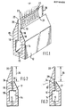
- a blade is shown having two side pieces 10 and 12, with a liquid conduit 14 being provided between them.
- the conduit runs along the length of the blade and is provided with liquid under pressure from a pump (not shown).
- a slot 16 is also provided between the side parts 10 and 12; the slot is between 120 and 380, e.g. 250, micrometres wide and receives liquid from the conduit 14 and conducts it to a liquid outlet 18, where the liquid collects as a bead 13.
- the width of slot 16 is determined by the width of a shim 15 and can be changed by changing the shim for one of different thickness.
- side piece 10 extends beyond side piece 12 and thus provides a surface 20 leading from the liquid outlet 18 to a discharge edge 22 at the end of side piece 10.
- the side pieces are held together by bolts (not shown) preferably the arrangement being such that the two side pieces can slide with respect to each other when the bolts are not fully tightened but, when fully tightened, the bolts clamp the side pieces and prevent any sliding movement.
- This arrangement allows the distance between discharge edge 22 and outlet 18 to be adjusted.
- the side piece 10 is made of a non-conductive material, e.g. polymethylmethacrylate or an epoxy resin (Perspex or Tufnol, which are Trade Marks), ceramics or any other insulating material.
- the other side piece 12 may be made of metal, e.g. aluminium, and is connected to a high voltage source in order to supply electrostatic charge to the liquid at the outlet 18.
- side piece 12 may be made of a non-conductive material in which case there should be a conductive wire or strip in the slot 16 to provide charge to the liquid at the outlet 18.
- Such a strip is shown in Figure 2 by the reference numeral 24 and is connected to a high voltage source ; the strip is embedded in side piece 10 which is made of insulating material as is side piece 12.
- the strip 24 may equally be embedded in side piece 12 or a strip 24 may be embedded in both of side pieces 10 and 12.
- the strip 24 may be in the position shown or it may be located further down the slot 16.
- the distance 26 between the slot outlet 18 and the discharge edge 22 is between 0.5 and 4 mm, e.g. approximately 2.5 mm.
- an electrode 19 may be placed on or near the outer side of the non-conductive side piece 10 to counteract the field produced by the conductive side piece 12. If electrode 19 were not provided, the liquid might migrate and wet the outer surface of side piece 10.
- the electrode may be in the form of a conductive layer or plate attached to the side piece 10 or it may be a plate spaced slightly from the side piece 10.
- liquid collects at the outlet 18 as a bead of liquid 13 and is maintained there either by providing a flat surface 25 at the top of side piece 12 (see Figure 2) or by providing a groove 28 in side piece 10 in which the liquid can accumulate as shown in
- a strip of conductive material 24 may be provided within or below the groove 28 to supply electrostatic charge to the liquid.
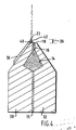
- the blade shown in Figure 4 has two side pieces 30 and 32 both made of aluminium and a spacing shim 15 located between them.
- a liquid conduit 14 extends along practically the whole length of the blade and a single slot 16 is provided for conducting the liquid from conduit 14 to an outlet 18.
- the width of slot 16 is determined by the width of the shim 15.
- a strip 36 of 1.5 mm thick Tufnol (Trade mark), which is an insulating material, is secured to the outer surface of blade side piece 30 and extends so that a leading edge 22 of the strip lies in front of the outlet 18 .
- the distance 26 between the slot outlet 18 and the leading (or discharge) edge 22 is approximately 2.5 mn.
- the blades shown in Figs 1 to 3 operate as follows: liquid is supplied under slight pressure to conduit 14 and it flows along slot 16 to outlet 18 where it collects as a bead 13.
- An electrostatic field is established between the blade and the object to be coated usually by holding the object at earth potential and charging the blade up to the working potential of 50 to 120 kV. This potential is supplied to side piece 12 when it is conductive or to strip 24 when sidepiece 12 is non-conductive. The liquid is thereby also charged.
- the electrostatic field draws the liquid 21 from the outlet 18 to the discharge edge 22.
- the liquid stream flowing along surface 20 rapidly decreases in thickness as it approaches discharge edge 22 and it may actually be formed into distinct rivulets 23 as shown in Figure 1 or it may reach the edge 22 as a single stream. In either case, only a small amount of liquid reaches the discharge edge, where it is atomised.
- the discharge is constant even at low discharge rates.
- the operation of the blade shown in Fig 4 is very similar to the operation of the blades shown in Figs 1 to 3. Electrostatic charge is applied to the liquid at the outlet via the side piece 30 and/or 32, the liquid collects as a bead 40 at the outlet 18 but that bead does not extend as far as discharge edge 22. Liquid from the bead is accelerated under the influence of the applied electrostatic field along surface 42 of the strip 36 until it reaches the leading edge where it is discharged. As it is drawn along surface 42 by the electrostatic field, the liquid forms a film of decreasing thickness and in this way, very small discharge rates of liquid can be achieved as described above.
- baldes can also be operated to provide much higher discharge rates.
- the blade according to the present invention is primarily designed to coat objects with oil to protect them from corrosion but it may also be used to apply any liquid that is customarily applied by electrostatic coating techniques.
- An electrostatic coating blade as shown in Figure 4 was used to coat an object with Nalco oil (type XL 174) having a resistivity 6.5 x 10 7 ohm cms at 35 0 C.
- the target object is held at earth potential and the blade is charged to a negative potential of 90 kV.
- the insulating strip is made of 6F45 Tufnol (Tufnol is a Trade Mark) which is an epoxy resin containing a fine weave fabric.
- the target object is located 9 inches (23 cms) from the blade.
- a discharge rate of 0.03 ml/cm of blade length/minute was obtained while still producing a uniform, continuous coating of the oil.
- the voltage was then increased to 120 kV and the rate of liquid supply to the blade was increased. Using these parameters, a discharge rate of 15 ml/cm of blade length/minute was obtained.
- a blade as illustrated in US-PS-2,695,002 was used to coat a similar object with XL 174-type Nalco oil; the minimum discharge rate that could be obtained was 0.5 ml/cm of blade length/minute but even at this rate, the object had uncoated patches caused by the fact that the blade produced large droplets.
- the blade of US-PS-2,695,002 required a discharge rate of 1.2 ml/cm of blade length/minute, i.e. 40 times that required by the present invention.
Landscapes
- Electrostatic Spraying Apparatus (AREA)
- Application Of Or Painting With Fluid Materials (AREA)
- Coating Apparatus (AREA)
Priority Applications (1)
| Application Number | Priority Date | Filing Date | Title |
|---|---|---|---|
| AT86306460T ATE38478T1 (de) | 1985-09-03 | 1986-08-20 | Rakel zum elektrostatischen beschichten und verfahren zum elektrostatischen bespruehen. |
Applications Claiming Priority (4)
| Application Number | Priority Date | Filing Date | Title |
|---|---|---|---|
| GB8521835 | 1985-09-03 | ||
| GB858521835A GB8521835D0 (en) | 1985-09-03 | 1985-09-03 | Electrostatic coating blade |
| GB8522144 | 1985-09-06 | ||
| GB858522144A GB8522144D0 (en) | 1985-09-06 | 1985-09-06 | Electrostatic coating blade |
Publications (2)
| Publication Number | Publication Date |
|---|---|
| EP0216502A1 true EP0216502A1 (fr) | 1987-04-01 |
| EP0216502B1 EP0216502B1 (fr) | 1988-11-09 |
Family
ID=26289725
Family Applications (1)
| Application Number | Title | Priority Date | Filing Date |
|---|---|---|---|
| EP86306460A Expired EP0216502B1 (fr) | 1985-09-03 | 1986-08-20 | Racle pour le revêtement électrostatique et méthode de pulvérisation électrostatique |
Country Status (8)
| Country | Link |
|---|---|
| US (1) | US4830872A (fr) |
| EP (1) | EP0216502B1 (fr) |
| JP (1) | JPH0815577B2 (fr) |
| KR (1) | KR870002874A (fr) |
| CA (1) | CA1260327A (fr) |
| DE (2) | DE216502T1 (fr) |
| ES (1) | ES2001639A6 (fr) |
| SU (1) | SU1547697A3 (fr) |
Cited By (7)
| Publication number | Priority date | Publication date | Assignee | Title |
|---|---|---|---|---|
| US4749125A (en) * | 1987-01-16 | 1988-06-07 | Terronics Development Corp. | Nozzle method and apparatus |
| US4846407A (en) * | 1986-04-21 | 1989-07-11 | Imperial Chemical Industries Plc | Electrostatic spraying apparatus |
| EP0470712A1 (fr) * | 1990-08-09 | 1992-02-12 | Imperial Chemical Industries Plc | Pulvérisation des liquides |
| US5162193A (en) * | 1989-11-21 | 1992-11-10 | Du Pont-Howson Limited | Radiation sensitive devices |
| US5332154A (en) * | 1992-02-28 | 1994-07-26 | Lundy And Associates | Shoot-up electrostatic nozzle and method |
| FR2950545A1 (fr) * | 2009-09-29 | 2011-04-01 | Centre Nat Rech Scient | Dispositif et procede de projection electrostatique d'un liquide, injecteur de carburant incorporant ce dispositif et utilisations de ce dernier |
| EP2665559A4 (fr) * | 2011-01-19 | 2017-06-28 | Washington University | Buse d'atomisation électrohydrodynamique émettant une feuille de liquide |
Families Citing this family (30)
| Publication number | Priority date | Publication date | Assignee | Title |
|---|---|---|---|---|
| JP3038879B2 (ja) * | 1989-11-21 | 2000-05-08 | セイコーエプソン株式会社 | ノズルレスインクジェット記録ヘッド |
| US5165601A (en) * | 1990-04-11 | 1992-11-24 | Terronics Development Corporation | Nozzle for low resistivity flowable material |
| US5209410A (en) * | 1992-03-05 | 1993-05-11 | United Air Specialists, Inc. | Electrostatic dispensing nozzle assembly |
| US5326598A (en) * | 1992-10-02 | 1994-07-05 | Minnesota Mining And Manufacturing Company | Electrospray coating apparatus and process utilizing precise control of filament and mist generation |
| GB9225098D0 (en) | 1992-12-01 | 1993-01-20 | Coffee Ronald A | Charged droplet spray mixer |
| US6105571A (en) | 1992-12-22 | 2000-08-22 | Electrosols, Ltd. | Dispensing device |
| US6880554B1 (en) | 1992-12-22 | 2005-04-19 | Battelle Memorial Institute | Dispensing device |
| US5441204A (en) * | 1993-06-10 | 1995-08-15 | United Air Specialists, Inc. | Electrostatic fluid distribution nozzle |
| GB9416581D0 (en) * | 1993-09-02 | 1994-10-12 | Ici Plc | Electrostatic spraying device |
| GB9406171D0 (en) * | 1994-03-29 | 1994-05-18 | Electrosols Ltd | Dispensing device |
| GB9410658D0 (en) * | 1994-05-27 | 1994-07-13 | Electrosols Ltd | Dispensing device |
| US5503336A (en) * | 1994-07-14 | 1996-04-02 | United Air Specialists | High volume - low volume electrostatic dispensing nozzle assembly |
| US6252129B1 (en) | 1996-07-23 | 2001-06-26 | Electrosols, Ltd. | Dispensing device and method for forming material |
| US7193124B2 (en) | 1997-07-22 | 2007-03-20 | Battelle Memorial Institute | Method for forming material |
| US6422848B1 (en) | 1997-03-19 | 2002-07-23 | Nordson Corporation | Modular meltblowing die |
| GB2327895B (en) | 1997-08-08 | 2001-08-08 | Electrosols Ltd | A dispensing device |
| US6012657A (en) * | 1997-10-03 | 2000-01-11 | Nordson Corporation | Powder spray head for fan-like patterns |
| US6368409B1 (en) | 1997-11-25 | 2002-04-09 | Nordson Corporation | Electrostatic dispensing apparatus and method |
| JP4677102B2 (ja) | 1999-04-23 | 2011-04-27 | バテル・メモリアル・インスティテュート | エーロゾル給送装置及びエーロゾル小滴を給送する方法 |
| US6737113B2 (en) * | 2001-01-10 | 2004-05-18 | 3M Innovative Properties Company | Method for improving the uniformity of a wet coating on a substrate using pick-and-place devices |
| US20020192360A1 (en) * | 2001-04-24 | 2002-12-19 | 3M Innovative Properties Company | Electrostatic spray coating apparatus and method |
| US6579574B2 (en) | 2001-04-24 | 2003-06-17 | 3M Innovative Properties Company | Variable electrostatic spray coating apparatus and method |
| US6534129B1 (en) | 2001-10-30 | 2003-03-18 | Nordson Corporation | Electrostatic liquid dispensing apparatus and method |
| US7045934B2 (en) * | 2002-04-11 | 2006-05-16 | Ernest Geskin | Method for jet formation and the apparatus for the same |
| GB0308021D0 (en) * | 2003-04-07 | 2003-05-14 | Aerstream Technology Ltd | Spray electrode |
| KR100648411B1 (ko) * | 2003-10-17 | 2006-11-24 | 주식회사 디엠에스 | 유체분사노즐 |
| EP1729887A4 (fr) | 2004-04-02 | 2008-12-31 | Wladimir Jassen | Systeme efficace et souple de depot electrostatique a buses de pulverisation multiples |
| US7740350B2 (en) * | 2005-06-15 | 2010-06-22 | Xerox Corporation | Printing apparatus |
| US20090297323A1 (en) * | 2008-05-30 | 2009-12-03 | Genesis Worldwide Ii, Inc. | Method and apparatus for stacking sheet materials |
| JP5976324B2 (ja) * | 2012-01-05 | 2016-08-23 | ナノミストテクノロジーズ株式会社 | 静電霧化装置 |
Citations (3)
| Publication number | Priority date | Publication date | Assignee | Title |
|---|---|---|---|---|
| US2695002A (en) * | 1950-06-24 | 1954-11-23 | Ransburg Electro Coating Corp | Electrostatic atomizer of liquids |
| US3486483A (en) * | 1968-08-23 | 1969-12-30 | Richard Tilney | Electrostatic spray coating apparatus |
| WO1984001524A1 (fr) * | 1982-10-21 | 1984-04-26 | Sale Tilney Technology Plc | Lames de revetement electrostatique, appareils comprenant de telles lames et procedes utilisant de telles lames |
Family Cites Families (4)
| Publication number | Priority date | Publication date | Assignee | Title |
|---|---|---|---|---|
| US2860599A (en) * | 1954-08-13 | 1958-11-18 | Binks Mfg Co | Electrostatic coating device with restricted fluid passageway opening adjacent sharpdischarge edge |
| US2782074A (en) * | 1957-01-15 | 1957-02-19 | Sedlacsik John | Electrostatic spraying apparatus |
| DE2059594C3 (de) * | 1970-07-31 | 1973-09-20 | Hajtomue Es Felvonogyar, Budapest | Vorrichtung zum elektrostatischen Aufstäuben von Farbstoffen, Pulver,Faserstoffen u.dgl |
| IE45426B1 (en) * | 1976-07-15 | 1982-08-25 | Ici Ltd | Atomisation of liquids |
-
1986
- 1986-08-20 DE DE198686306460T patent/DE216502T1/de active Pending
- 1986-08-20 DE DE8686306460T patent/DE3661121D1/de not_active Expired
- 1986-08-20 EP EP86306460A patent/EP0216502B1/fr not_active Expired
- 1986-08-20 US US06/898,260 patent/US4830872A/en not_active Expired - Lifetime
- 1986-08-26 JP JP61198294A patent/JPH0815577B2/ja not_active Expired - Lifetime
- 1986-09-02 CA CA000517306A patent/CA1260327A/fr not_active Expired
- 1986-09-02 KR KR1019860007329A patent/KR870002874A/ko not_active Withdrawn
- 1986-09-02 ES ES8601572A patent/ES2001639A6/es not_active Expired
- 1986-09-03 SU SU864028118A patent/SU1547697A3/ru active
Patent Citations (3)
| Publication number | Priority date | Publication date | Assignee | Title |
|---|---|---|---|---|
| US2695002A (en) * | 1950-06-24 | 1954-11-23 | Ransburg Electro Coating Corp | Electrostatic atomizer of liquids |
| US3486483A (en) * | 1968-08-23 | 1969-12-30 | Richard Tilney | Electrostatic spray coating apparatus |
| WO1984001524A1 (fr) * | 1982-10-21 | 1984-04-26 | Sale Tilney Technology Plc | Lames de revetement electrostatique, appareils comprenant de telles lames et procedes utilisant de telles lames |
Cited By (10)
| Publication number | Priority date | Publication date | Assignee | Title |
|---|---|---|---|---|
| US4846407A (en) * | 1986-04-21 | 1989-07-11 | Imperial Chemical Industries Plc | Electrostatic spraying apparatus |
| US4749125A (en) * | 1987-01-16 | 1988-06-07 | Terronics Development Corp. | Nozzle method and apparatus |
| US5162193A (en) * | 1989-11-21 | 1992-11-10 | Du Pont-Howson Limited | Radiation sensitive devices |
| EP0470712A1 (fr) * | 1990-08-09 | 1992-02-12 | Imperial Chemical Industries Plc | Pulvérisation des liquides |
| US5332154A (en) * | 1992-02-28 | 1994-07-26 | Lundy And Associates | Shoot-up electrostatic nozzle and method |
| FR2950545A1 (fr) * | 2009-09-29 | 2011-04-01 | Centre Nat Rech Scient | Dispositif et procede de projection electrostatique d'un liquide, injecteur de carburant incorporant ce dispositif et utilisations de ce dernier |
| WO2011039695A1 (fr) * | 2009-09-29 | 2011-04-07 | Centre National De La Recherche Scientifique | Dispositif et procede de projection electrostatique d'un liquide, injecteur de carburant incorporant ce dispositif et utilisations de ce dernier |
| US9188332B2 (en) | 2009-09-29 | 2015-11-17 | Centre National De La Recherche Scientifique | Device and method for electrostatically spraying a liquid |
| EP2665559A4 (fr) * | 2011-01-19 | 2017-06-28 | Washington University | Buse d'atomisation électrohydrodynamique émettant une feuille de liquide |
| US10562048B2 (en) | 2011-01-19 | 2020-02-18 | Nanocopoeia, Llc | Electrohydrodynamic atomization nozzle emitting a liquid sheet |
Also Published As
| Publication number | Publication date |
|---|---|
| DE216502T1 (de) | 1987-07-23 |
| KR870002874A (ko) | 1987-04-13 |
| JPH0815577B2 (ja) | 1996-02-21 |
| ES2001639A6 (es) | 1988-06-01 |
| US4830872A (en) | 1989-05-16 |
| DE3661121D1 (en) | 1988-12-15 |
| SU1547697A3 (ru) | 1990-02-28 |
| JPS6257664A (ja) | 1987-03-13 |
| CA1260327A (fr) | 1989-09-26 |
| EP0216502B1 (fr) | 1988-11-09 |
Similar Documents
| Publication | Publication Date | Title |
|---|---|---|
| US4830872A (en) | Electrostatic coating blade and method of applying a thin layer of liquid therewith onto an object | |
| EP0662866B1 (fr) | Appareil et procede d'enduction par electropulverisation | |
| EP1056546B1 (fr) | Pistolet pulverisateur a sonde anti-ionisation inverse dote d'un systeme de commande | |
| CA1284272C (fr) | Dispositif de pistolage electrostatique | |
| EP1870169B1 (fr) | Systeme de revetement de feuille d'isolation electrique et procede de production de feuille d'isolation electrique recouverte d'un film | |
| US3726701A (en) | Method for controlling deposit of coating material in electrostatic coating | |
| JPS6250192B2 (fr) | ||
| US20250050370A1 (en) | Spray Head Improvements for an Ultrasonic Spray Coating Assembly | |
| US4597533A (en) | Electrostatic spraying apparatus | |
| US5332154A (en) | Shoot-up electrostatic nozzle and method | |
| US3687368A (en) | Valve unit for air type electrostatic spray gun | |
| CA2101358C (fr) | Jet applicateur pour l'application d'un revetement sur une trame de papier et methode | |
| GB1558924A (en) | Electrostatic coating grid and method | |
| CA2018551C (fr) | Procede et appareil de pulverisation electrostatique | |
| ITMI20001023A1 (it) | Dispositivo per verniciatura elettrostatica, a geometria con profilo venturi planare per emissione lineare e a densita' uniforme di polvere, | |
| US4119522A (en) | Nozzle apparatus for electrophoretic coating of interior surfaces | |
| US5938126A (en) | Spray gun having a current monitored anti-back-ionization probe | |
| CN1429138B (zh) | 采用聚焦板材电荷场的静电辅助涂覆方法和装置 | |
| GB2183509A (en) | Electrostatic coating apparatus | |
| US4488505A (en) | Electronic strip oiler | |
| JP3211407B2 (ja) | 合金鍍金用電極 | |
| JPH0985133A (ja) | 静電塗装ガン | |
| ITMI20010654A1 (it) | Dispositivo per verniciatura elettrostatica ad emissione lineare di polvere attraverso una doppia fenditura di qualsivoglia lunghezza per us | |
| EP0291637B1 (fr) | Buse de mouillage pour machine à imprimer | |
| JPH0694600B2 (ja) | 移動する金属ストリツプの一面の電解被覆のための方法と装置 |
Legal Events
| Date | Code | Title | Description |
|---|---|---|---|
| PUAI | Public reference made under article 153(3) epc to a published international application that has entered the european phase |
Free format text: ORIGINAL CODE: 0009012 |
|
| AK | Designated contracting states |
Kind code of ref document: A1 Designated state(s): AT BE CH DE FR GB IT LI LU NL SE |
|
| DET | De: translation of patent claims | ||
| 17P | Request for examination filed |
Effective date: 19870914 |
|
| 17Q | First examination report despatched |
Effective date: 19880129 |
|
| ITF | It: translation for a ep patent filed | ||
| GRAA | (expected) grant |
Free format text: ORIGINAL CODE: 0009210 |
|
| AK | Designated contracting states |
Kind code of ref document: B1 Designated state(s): AT BE CH DE FR GB IT LI LU NL SE |
|
| REF | Corresponds to: |
Ref document number: 38478 Country of ref document: AT Date of ref document: 19881115 Kind code of ref document: T |
|
| REF | Corresponds to: |
Ref document number: 3661121 Country of ref document: DE Date of ref document: 19881215 |
|
| ET | Fr: translation filed | ||
| PGFP | Annual fee paid to national office [announced via postgrant information from national office to epo] |
Ref country code: BE Payment date: 19890531 Year of fee payment: 4 |
|
| PGFP | Annual fee paid to national office [announced via postgrant information from national office to epo] |
Ref country code: AT Payment date: 19890717 Year of fee payment: 4 |
|
| PLBI | Opposition filed |
Free format text: ORIGINAL CODE: 0009260 |
|
| PGFP | Annual fee paid to national office [announced via postgrant information from national office to epo] |
Ref country code: CH Payment date: 19890811 Year of fee payment: 4 |
|
| PGFP | Annual fee paid to national office [announced via postgrant information from national office to epo] |
Ref country code: SE Payment date: 19890828 Year of fee payment: 4 Ref country code: LU Payment date: 19890828 Year of fee payment: 4 |
|
| PGFP | Annual fee paid to national office [announced via postgrant information from national office to epo] |
Ref country code: FR Payment date: 19890829 Year of fee payment: 4 Ref country code: DE Payment date: 19890829 Year of fee payment: 4 |
|
| PG25 | Lapsed in a contracting state [announced via postgrant information from national office to epo] |
Ref country code: LU Free format text: LAPSE BECAUSE OF NON-PAYMENT OF DUE FEES Effective date: 19890831 |
|
| PGFP | Annual fee paid to national office [announced via postgrant information from national office to epo] |
Ref country code: NL Payment date: 19890831 Year of fee payment: 4 |
|
| 26 | Opposition filed |
Opponent name: IMPERIAL CHEMICAL INDUSTRIES PLC Effective date: 19890801 |
|
| NLR1 | Nl: opposition has been filed with the epo |
Opponent name: IMPERIAL CHEMICAL INDUSTRIES PLC |
|
| RDAG | Patent revoked |
Free format text: ORIGINAL CODE: 0009271 |
|
| STAA | Information on the status of an ep patent application or granted ep patent |
Free format text: STATUS: PATENT REVOKED |
|
| ITTA | It: last paid annual fee | ||
| REG | Reference to a national code |
Ref country code: CH Ref legal event code: PL |
|
| 27W | Patent revoked |
Effective date: 19900420 |
|
| GBPR | Gb: patent revoked under art. 102 of the ep convention designating the uk as contracting state | ||
| NLR2 | Nl: decision of opposition | ||
| BERE | Be: lapsed |
Owner name: SALE TILNEY TECHNOLOGY P.L.C. Effective date: 19900831 |
|
| EUG | Se: european patent has lapsed |
Ref document number: 86306460.6 Effective date: 19900919 |