EP0217478A1 - Contactless angle transducer - Google Patents
Contactless angle transducer Download PDFInfo
- Publication number
- EP0217478A1 EP0217478A1 EP86201692A EP86201692A EP0217478A1 EP 0217478 A1 EP0217478 A1 EP 0217478A1 EP 86201692 A EP86201692 A EP 86201692A EP 86201692 A EP86201692 A EP 86201692A EP 0217478 A1 EP0217478 A1 EP 0217478A1
- Authority
- EP
- European Patent Office
- Prior art keywords
- films
- angle transducer
- signal processing
- magnet
- processing unit
- Prior art date
- Legal status (The legal status is an assumption and is not a legal conclusion. Google has not performed a legal analysis and makes no representation as to the accuracy of the status listed.)
- Granted
Links
- 239000010408 film Substances 0.000 claims abstract description 77
- 239000010409 thin film Substances 0.000 claims abstract description 26
- 238000012545 processing Methods 0.000 claims abstract description 24
- 239000007779 soft material Substances 0.000 claims abstract description 14
- 230000001747 exhibiting effect Effects 0.000 claims abstract description 6
- 238000004519 manufacturing process Methods 0.000 claims abstract description 6
- 239000000463 material Substances 0.000 claims description 3
- 239000000758 substrate Substances 0.000 claims description 3
- 238000000137 annealing Methods 0.000 claims description 2
- 230000005415 magnetization Effects 0.000 description 6
- 238000005259 measurement Methods 0.000 description 6
- 230000000694 effects Effects 0.000 description 4
- XAGFODPZIPBFFR-UHFFFAOYSA-N aluminium Chemical compound [Al] XAGFODPZIPBFFR-UHFFFAOYSA-N 0.000 description 3
- 229910052782 aluminium Inorganic materials 0.000 description 3
- 238000012937 correction Methods 0.000 description 3
- 230000001419 dependent effect Effects 0.000 description 3
- 230000006399 behavior Effects 0.000 description 2
- 239000011247 coating layer Substances 0.000 description 2
- 238000000151 deposition Methods 0.000 description 2
- 238000010586 diagram Methods 0.000 description 2
- 238000000034 method Methods 0.000 description 2
- 230000002093 peripheral effect Effects 0.000 description 2
- 230000035945 sensitivity Effects 0.000 description 2
- 238000012935 Averaging Methods 0.000 description 1
- 230000005355 Hall effect Effects 0.000 description 1
- 239000004020 conductor Substances 0.000 description 1
- 230000008021 deposition Effects 0.000 description 1
- 230000002349 favourable effect Effects 0.000 description 1
- 230000004907 flux Effects 0.000 description 1
- 238000009472 formulation Methods 0.000 description 1
- 238000010438 heat treatment Methods 0.000 description 1
- 238000003698 laser cutting Methods 0.000 description 1
- 239000007788 liquid Substances 0.000 description 1
- 239000000203 mixture Substances 0.000 description 1
- 230000001360 synchronised effect Effects 0.000 description 1
- 238000009966 trimming Methods 0.000 description 1
Images

Classifications
-
- G—PHYSICS
- G01—MEASURING; TESTING
- G01D—MEASURING NOT SPECIALLY ADAPTED FOR A SPECIFIC VARIABLE; ARRANGEMENTS FOR MEASURING TWO OR MORE VARIABLES NOT COVERED IN A SINGLE OTHER SUBCLASS; TARIFF METERING APPARATUS; MEASURING OR TESTING NOT OTHERWISE PROVIDED FOR
- G01D5/00—Mechanical means for transferring the output of a sensing member; Means for converting the output of a sensing member to another variable where the form or nature of the sensing member does not constrain the means for converting; Transducers not specially adapted for a specific variable
- G01D5/12—Mechanical means for transferring the output of a sensing member; Means for converting the output of a sensing member to another variable where the form or nature of the sensing member does not constrain the means for converting; Transducers not specially adapted for a specific variable using electric or magnetic means
- G01D5/14—Mechanical means for transferring the output of a sensing member; Means for converting the output of a sensing member to another variable where the form or nature of the sensing member does not constrain the means for converting; Transducers not specially adapted for a specific variable using electric or magnetic means influencing the magnitude of a current or voltage
Definitions
- the invention relates to an angle transducer having at least one magnetically active element that is connected with a control and signal processing unit and a magnet co-operating therewith and relatively thereto rotatably positioned in such a way that an electrical property of that or each magnetically active element varies in dependence upon its angular position relative to the magnet, said control and signal processing unit being adapted for measuring the value of a quantity related with said property and generating a signal representative for said value and thus for said relative angular position.
- Such a prior art angle transducer has a number of disadvantages. It uses the ordinary Hall-effect, according to which the voltage supplied by the Hall-element is proportional with the magnetic flux. Due thereto this voltage is dependent upon the strength of the magnet and the distance of the magnet to the sensor.
- the strength of magnets is, in general, difficult to control, i.e. magnets cannot always be manufactured such that their strength is between narrow, predetermined tolerance limits. 'This fact, together with the critical distance of the magnet to the sensor implies that the angle transducer is more difficult to manufacture.
- the modulation depth is temperature dependent, even in case of application of a bridge circuit. Therefore additional compensation circuits are necessary, unless a low accuracy is accepted.
- Purpose of the invention is the provision of an angle transducer, that has not the above-mentioned disadvantages of the prior art.
- the aim is to engineer the angle transducer in such a way, that it can be manufacturing simply and thus cheaply, and nevertheless, if desired having a high accuracy and the control and signal processing unit may be simple.
- the signal supplied by the transducer and representative for the relative angular position to be measured is not proportional with that angular position, but varies with the sin 2 of the angular position.
- modulation depth can, due to the nature of the measurement, not be larger than in the order of 2%. This has the consequence that the additional electronics have to satisfy extreme requirements in order to achieve an acceptable resolution and an acceptable measuring accuracy. In practice the electronics cannot satisfy such requirements.
- both films are ring-shaped a higher output voltage is obtained upto in the order of magnitude of a factor ten, in comparison with an angle transducer provided with disc-shaped films having approximately the same dimensions and through which the same current flows.
- a part of the ring-shaped film extending between a current passing terminal and a voltage measuring terminal is in the form of a plurality of concentrically arranged strips, each of said strips extending over an angle of 90°, and said strips in meander-fashion electrically connected with their ends by means of radial connection strips.
- the connection strips have an electrical resistance substantially zero.
- the signal processing means are adapted for calculating said angular position from both said voltages according to the relations: in which
- the signal processing means are adapted for calculating said angular position from both said voltages according to the relations: in which
- control and signal processing unit As simply as possible and to avoid as much as possible dimensioning effects, advantageously use may be made of an alternative embodiment in which the films are identical.
- both films are rotation-symmetrical. In general sharp angles are as much as possible avoiding in order to avoid domain forming.
- Rotation symmetry has the advantage of identical magnetic behaviour of both elements. In case of a circle-shaped ring shape effects cancel by averaging, due to which the measuring linearity is excellently guaranteed. It should be noted that “rotation-symmetry" and “ring-shaped” should be interpreted in such a broad sense, that the alternative embodiment with the ring constructed in the way of a meander is covered by that formulation.
- the electronic control and signal processing unit can be constructed even more easily, whilst furthermore it can be considered as an advantage that heating phenomena are equal in both films.
- An extremely high accuracy can, if desired, be achieved with an embodiment which is characterized by, means for compensating error-angles occurring due to the magnetical anisotropy of the thin films, in which the distance of the magnet relative to the thin films, the strength of the magnet, and the shapes of the magnet and the films are chosen in such a way, that the shape of the magnetic field in the region of the thin films and said error-angle compensate for each other at least more or less.
- the accuracy achieved with this embodiment is not accompanied by a strong increase of the manufacturing costs.
- Balancing problems can substantially completely be avoided with an embodiment exhibiting the feature that both thin films are in the form of one film, that the control means are adapted for successively and alternately passing current through the one set and the other set currents passing terminals respectively, and that the measuring means are adapted for successively and alternately measuring the voltages belonging thereto.
- the advantage of very simple electronics is more or less cancelled by the necessity to control and to measure in a switching fashion. Within one element an imbalance can occur disturbing the sine-shape of the angular sensitivity.
- the magnetic element in the region of the sensor should be rectilinear within the required accuracy, now to be less dependent upon the position and the properties of the magnet one can use a method of manufacturing a ring-shaped strip of magnetically soft material for an angle transducer according to which method one manufactures a ring-shaped strip of magnetically soft material and uses the shape-preference direction extending tangentially along the ring, in order to direct the intrisic or material preference during an annealing operation, i.e. a temporary temperature increase of the ring upto in the order of magnitude of 300-350°C.
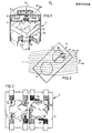
- the carrier plate 3 furthermore supports an electronic control and signal processing unit, consisting of integrated circuits 8 and 9 that can be connected with peripheral equipment and an electrical supply by means of a cable 10.
- the house 2 that by means not-shown can be rigidly coupled with a member, device or the like, the angular position of which has to be determined relative to another element, another device or the like, furthermore carries an alphanumerical presentation unit 11 provided with liquid cristals, on which the measured angular position is displayed in a directly readable manner.
- permanent magnet 12 is positioned on a shaft 13 in such a way that it is rotatable relative to the house.
- the axis of the shaft 13 extends to the centre of the integrated unit 4.
- the shaft 13 is beared in a relatively thick closing plate 14 of the house 2 and secured by a peripheral shoulder 15 on the one hand and by a securing ring 16 on the other hand.
- connection conductors between the integrated unit 4 on the one hand and the integrated circuits 8, 9 on the other hand are not shown.
- the angle transducer 1 is adapted for the determination of the angle between the house 2 and the orientation of the magnetization of magnet 12, therefore, between the house 1 and the shaft 13. If the house 2 is coupled with the one element and the shaft 13 with the other element, thus the angle transducer 1 can assess the angular position between both elements.
- fig. 2 shows the integrated unit 4.
- the thin films 6, 7 are provided with current passing terminals 17, 18 and 19, 20, respectively.
- the contacts 17, 18 and 19, 20, respectively, are arranged in diagonal relation. Also in diagonal relation, but in transverse direction relative to the mentioned current passing terminals 17, 18 and 19, 20 the films 6, 7 are provided with voltage measuring terminals 21, 22 and 23, 24, respectively.
- the planar Hall-voltage is measured at the voltage measuring terminals 21, 22 and 23, 24 respectively.
- the current passing terminals 17, 18 are positioned on a diagonal forming an angle of 45° with the diagonal connecting the current passing terminals 19, 20. Mutatis mutandis the same is valid for the voltage measuring terminals 21, 22 and 23, 24, respectively.
- Fig. 4 shows by way of example an electronic circuit of which the integrated unit 4 may form part.
- a sine generator 25 generates two AC-currents relatively phase-shifted with 90°, I sin (w t) and I cos (w t) at respective output terminals 26 and 27.
- the terminal 26 is connected with the current passing terminals 17, 18 of the thin film 6, which is shown for the sake of ease of one line and the terminal 27 is connected with the current passing terminals 19, 20 of the thin film 7.
- the voltage at the voltage measuring terminals 21, 22 of the thin film 6 is supplied to the one input 28 of a comparator 30, whilst the voltage at the voltage measuring terminals 23, 24 of the thin film 7 is supplied to the other terminal 29 of the comparator 30.
- the sine generator 25 supplies through an output 21 a voltage proportional with the phase of the output signal at terminal 26, i.e. linearly varying voltage periodically returning to zero, a sawtooth voltage. It is noted that this relates to an analog technique, whilst as will be understood also digitally operating circuits may be used.
- the output signals of films 6, 7, i.e. the signals at the inputs 28 and 29 of comparator 30 are proportional with I sin(M t).cos(2 ), en I.cos (0 t) and I cos(w t).sin(20 ), respectively, in which 0 is the angle between the house 2 according to fig. 1 and the shaft 13 on which the magnet 12 is fixed.
- the output 31 is connected with the information-input 31 of a memory/clock unit 33, the clock-input 34 of which is connected with the output 35 of comparator 30.
- the memory/clock unit 33 is connected with an analog display unit 53.
- Fig. 3 shows the integrated unit 4 according to fig. 2 in an inhomogeneous magnet field, that schematically is indicated with field lines 3.
- the relative positioning of magnet 12 and the unit 4 is such that the field line extending through the unit 4, that has been indicated with 36 for the sake of clarity, is a straight line.
- the connection line between the centre points of the magnetic films 6 and 7 does not coincide with the central field line 36, but forms an angle therewith.
- An arrow 38 indicates the preferred direction of the thin film 7.
- An arrow 39 indicates the direction of the field applied.
- the magnetization of the film 7 will not have the direction of the magnetic field according to arrow 39, but deviate therefrom irr the direction of the preferred direction 38.
- the magnetization is indicated with an interruptedly-shown arrow 40. It will be clear that due to the curvature of the field lines 37 in that region the magnetic field makes a certain angle with the direction of the central line 36, which if it would also be the magnetization of film 7, would introduce an angular error and thus a measuring error.
- the magnetization is directed in correspondence with arrow 14 as a result of the co-operation of the magnetical anisotropy of film 7 on the one hand and the shape of the magnetic field 37 applied a compensation occurs, in other words, the magnetization 40 extends in a more parallel relation with the field line 36 than magnet field 39.
- the above has for its purpose to indicate the principle on basis of which an angle transducer having an error angle as small as possible can be manufactured.
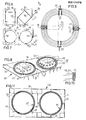
- Fig. 5 shows a schematic circuit in accordance with fig. 4.
- fig. 4 two magnetic films are used, whilst fig. 5 relates to an alternative embodiment in which both thin films are in the form of one film, in which in a switching manner successively current is passed through the one set and the other set of current passing terminals, respectively, whilst also in a switching fashion successively the related planar Hall-voltages are taken off the related voltage measuring terminals.
- a thin film 41 is provided with two sets of current passing terminals having a mutual angular position of 45° and two pairs of voltage measuring terminals exhibiting angles of 90° relative to their corresponding current passing terminals and the therefore exhibiting also a mutual relative angular position of 45°.
- the pairs of terminals are indicated with only one reference.
- With output terminal 26 of the sine generator 25 by means of a switch 42 a first pair of current passing terminals 43 is connected.
- a switch 44 connects output 27 with a second set of current passing terminals 45.
- the corresponding pairs of voltage measuring terminals of the thin film 41 are indicated with 46 and 47, respectively.
- a clock unit 52 controls the switches 42, 44, 48, 49 in a synchronous fashion. Due thereto successively current is passed through the terminals 43 and the measured voltage at the voltage measuring terminals 46 is passed through switch 48 to the sample and the hold circuit 50 and current is through switch 44 passed to the current passing terminals 45, the corresponding voltage at the terminals 47 is through switch 49 supplied to the sample and hold circuit 51.
- both films of a pair can also be positioned with small relative distance over each other.
- Parts of the embodiments according to figs. 6, 7, 8, 9, 10 and 11 to be discussed hereinafter corresponding with parts already mentioned of particularly the embodiment according to fig. 2 will be indicated with the same reference numerals as there and will not be discussed.
- Fig. 6 shows an integrated unit 54 for an angle transducer in plan view, corresponding to fig. 2.
- use is made of two films 55, 56 made of magnetically soft material each having the shape of a square ring.
- Fig. 7 shows an integrated unit 57 provided with two films 58, 59 made of magnetically soft material each having the shape of a circular ring.
- Fig. 8 shows an integrated unit 60 provided with two films 61, 62. Each part extending between a current passing terminal 17, 18; 19, 20 and a voltage measuring terminal 21, 22; 23, 24 of each film 61, 62 is in the form of three concentrically arranged strips, each extending over an angle of 90° and connected with their ends in the way of a meander by means of radial connection strips. The respective curvature-centres are all indicated with 64.
- the surface surrounded by each of the ring 61, 62, of the substrate 5, is used for carrying an IC 63.
- the IC's 63 comprise electronic circuits forming part of the angle transducer and which already have been discussed with reference to fig. 4.
- Fig. 9 shows a film 65 of magnetically soft material in an alternative embodiment of the film 61 according to fig. 8.
- Fig. 10 shows as the detail X according to fig. 8 that the ends of the respective parts of the film 61 are connected by means of a radial part of the film 61, which is electrically short-circuited by an aluminum coating layer 67.
- no radial connection strips of magnetically soft material are present between the ends of the film parts. The ends extend beyond the aluminum coating layers 67 operative as connection strips, which is favourable for the magnetic behaviour of the film parts at their ends.
- the terminals 17, 18, 21, 22 are in the form of aluminum strips, the ends of which are broadened in such a way that the concentric film parts between successive ends extend over exactly 90°.
- Fig. 11 at last shows an integrated unit 68 in plan view of an alternative embodiment of the unit 60 according to fig. 8.
- the films 61, 62 of the unit 60 comprise three concentric film parts, whilst the films 69, 70 comprise five concentric film parts.
Landscapes
- Physics & Mathematics (AREA)
- General Physics & Mathematics (AREA)
- Transmission And Conversion Of Sensor Element Output (AREA)
- Measurement Of Length, Angles, Or The Like Using Electric Or Magnetic Means (AREA)
- Ultra Sonic Daignosis Equipment (AREA)
- Investigating Or Analyzing Materials By The Use Of Ultrasonic Waves (AREA)
- Measuring Magnetic Variables (AREA)
Abstract
Description
- The invention relates to an angle transducer having at least one magnetically active element that is connected with a control and signal processing unit and a magnet co-operating therewith and relatively thereto rotatably positioned in such a way that an electrical property of that or each magnetically active element varies in dependence upon its angular position relative to the magnet, said control and signal processing unit being adapted for measuring the value of a quantity related with said property and generating a signal representative for said value and thus for said relative angular position.
- Such an angle transducer is known from US
patent specification 3 777 273. - Such a prior art angle transducer has a number of disadvantages. It uses the ordinary Hall-effect, according to which the voltage supplied by the Hall-element is proportional with the magnetic flux. Due thereto this voltage is dependent upon the strength of the magnet and the distance of the magnet to the sensor. The strength of magnets is, in general, difficult to control, i.e. magnets cannot always be manufactured such that their strength is between narrow, predetermined tolerance limits. 'This fact, together with the critical distance of the magnet to the sensor implies that the angle transducer is more difficult to manufacture.
- The modulation depth is temperature dependent, even in case of application of a bridge circuit. Therefore additional compensation circuits are necessary, unless a low accuracy is accepted.
- Purpose of the invention is the provision of an angle transducer, that has not the above-mentioned disadvantages of the prior art. The aim is to engineer the angle transducer in such a way, that it can be manufacturing simply and thus cheaply, and nevertheless, if desired having a high accuracy and the control and signal processing unit may be simple.
- These purposes are, according to the invention, generally realized by an angle transducer of the type mentioned in the preamble and which is characterized by
- at least one set of two mutually parallel flat thin films of magnetically soft material that it is kept in saturation by the magnet, said films exhibiting resistance anisotropy, having each two current passing terminals positioned at the ends of a first diagonal and two voltage measuring terminals positioned at the ends of a second diagonal positioned perpendicularly relative to said first diagonal, said first and said second diagonals forming angles of 45° with each other;
- control means forming part of the signal processing unit for supplying electrical currents through the current passing terminals of both films;
- measuring means forming part of the signal processing unit for measuring the voltages over the voltage measuring terminals of both films; and
- signal processing means forming part of the signal processing unit for calculating said angular position from both voltages.
- It should be noted that from the
German patent specification 29 15 461 a device is known for measuring rotation sense and rotation speed. With such a device only a AC-component can be measured, which is much more easy than a DC-component in case of stationary measurements. If this device would be used as an angle transducer it would exhibit a plurality of substantial drawbacks. - Firstly the signal supplied by the transducer and representative for the relative angular position to be measured is not proportional with that angular position, but varies with the sin2 of the angular position.
- Furthermore the modulation depth can, due to the nature of the measurement, not be larger than in the order of 2%. This has the consequence that the additional electronics have to satisfy extreme requirements in order to achieve an acceptable resolution and an acceptable measuring accuracy. In practice the electronics cannot satisfy such requirements.
- Use may be made of an embodiment in which both films are disc-shaped.
- In an embodiment in which both films are ring-shaped a higher output voltage is obtained upto in the order of magnitude of a factor ten, in comparison with an angle transducer provided with disc-shaped films having approximately the same dimensions and through which the same current flows.
- In order to maximize in this last-mentioned case the sensitivity as much as possible, one can use an embodiment having the special feature that a part of the ring-shaped film extending between a current passing terminal and a voltage measuring terminal is in the form of a plurality of concentrically arranged strips, each of said strips extending over an angle of 90°, and said strips in meander-fashion electrically connected with their ends by means of radial connection strips. In this case the connection strips have an electrical resistance substantially zero.
- For an embodiment, in which both films are in the form of round discs, the signal processing means are adapted for calculating said angular position from both said voltages according to the relations:

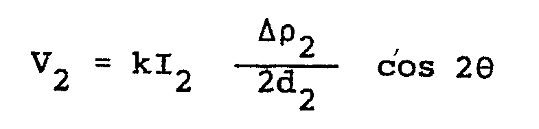
- V1 = the voltage over the first film
- V2 = the voltage over the second film
- I1 = the current through the first film
- 12 = the current through the second film
- Δρ1,2 = the anisotropic magneto-resistance effect
- d1 = the thickness of the first film
- d2 = the thickness of the second film
- θ = the relative angular position to be measured
- k = a calibration constant
- In the case, in which both thin films are in the form of roung rings the signal processing means are adapted for calculating said angular position from both said voltages according to the relations:


- V1 = the voltage over the first film
- V2 = the voltage over the second film
- II = the current through the first film
- 12 = the current through the second film
- Δρ1,2 = the anisotropic magneto-resistance effect
- d1 = the thickness of the first film
- d2 = the thickness of the second film
- r1 = the radius of the first ring upto the half width
- r2 = the radius of the first ring upto the half width
- w1 = the radial dimension of the first ring
- w2 = the radial dimension of the second ring
- 0 = the relative angular position to be measured which for r1,2 >> w1,2 passes to:


- On basis of the above-mentioned mathematical relations, in which the voltages occurring as a result of modulation of the resistance-anisotropy are brought into relation with the sine and the cosine, respectively, of the double value of the relative angular position to be measured, one can understand that the measurement of the relative angular position can be considered as the interpretation of a Lissajous-figure. In particular in the case in which the currents through both films are equal the anisotropic magneto-resistance-effect and the thicknesses of both films are equal, said Lissajous-figure is a circle. The measurement of the angular position, thus, is essentially a phase-measurement; namely, this Lissajous-figure is phase-linear. Even in case of a deviation of a current once adjusted the measurement can be performed in a reliable fashion as, namely, only the relation between both voltages is considered, in terms of a direction in a Lissajous-figure.
- In order to be able to construct the control and signal processing unit as simply as possible and to avoid as much as possible dimensioning effects, advantageously use may be made of an alternative embodiment in which the films are identical.
- In a preferred embodiment both films are rotation-symmetrical. In general sharp angles are as much as possible avoiding in order to avoid domain forming. Rotation symmetry has the advantage of identical magnetic behaviour of both elements. In case of a circle-shaped ring shape effects cancel by averaging, due to which the measuring linearity is excellently guaranteed. It should be noted that "rotation-symmetry" and "ring-shaped" should be interpreted in such a broad sense, that the alternative embodiment with the ring constructed in the way of a meander is covered by that formulation.
- In an embodiment in which the amplitudes of the currents through the current passing terminals of both films are equal the electronic control and signal processing unit can be constructed even more easily, whilst furthermore it can be considered as an advantage that heating phenomena are equal in both films.
- It will be obvious that the greatest advantages are obtained in the case, in which use is made of two identical, rotation-symmetrical thin films through which equal currents are passed.
- An extremely high accuracy can, if desired, be achieved with an embodiment which is characterized by, means for compensating error-angles occurring due to the magnetical anisotropy of the thin films, in which the distance of the magnet relative to the thin films, the strength of the magnet, and the shapes of the magnet and the films are chosen in such a way, that the shape of the magnetic field in the region of the thin films and said error-angle compensate for each other at least more or less. The accuracy achieved with this embodiment is not accompanied by a strong increase of the manufacturing costs.
- Balancing problems can substantially completely be avoided with an embodiment exhibiting the feature that both thin films are in the form of one film, that the control means are adapted for successively and alternately passing current through the one set and the other set currents passing terminals respectively, and that the measuring means are adapted for successively and alternately measuring the voltages belonging thereto. In this last-mentioned embodiment the advantage of very simple electronics is more or less cancelled by the necessity to control and to measure in a switching fashion. Within one element an imbalance can occur disturbing the sine-shape of the angular sensitivity. The provision of two additional strips, in case of a ring or disc-shaped sensor in parallel relation with one side of the element and in case of a meander-shaped sensor in series with the meanders in such a way that they contribute only to a small degree to the total output voltage, can offer a solution. By laser-cutting or another trimming operation in these strips the imbalance can be cancelled. A small deviation due to roughness of cuts or do to unequal shapes is the result. This deviation, however, is very small, as the contribution of these parts to the output voltage of the element is very small.
- In view of the required accuracy of the angle transducer the magnetic element in the region of the sensor should be rectilinear within the required accuracy, now to be less dependent upon the position and the properties of the magnet one can use a method of manufacturing a ring-shaped strip of magnetically soft material for an angle transducer according to which method one manufactures a ring-shaped strip of magnetically soft material and uses the shape-preference direction extending tangentially along the ring, in order to direct the intrisic or material preference during an annealing operation, i.e. a temporary temperature increase of the ring upto in the order of magnitude of 300-350°C.
- The invention will now be explained with reference to the drawing of some arbitrary embodiments, to which the invention, however, is not limited.
-
- Fig. 1 is a perspective view, partially broken away of an angle transducer according to the invention;
- Fig. 2 is a chip provided with two flat thin films of magnetically soft material as is used in the embodiment according to fig. 1;
- Fig. 3 is the chip according to fig. 2 in an inhomogeneous magnetic field, as an explanation of the error-angle compensation as a result of magnetical anisotropy of the thin films;
- Fig. 4 is a block schematic diagram of the device according to fig. 1;
- Fig. 5 is a block schematic diagram corresponding with fig. 4 of an alternative embodiment, in which both films are in the form of one film;
- Fig. 6 is a plan view of an alternative embodiment provided with films having the shapes of square rings;
- Fig. 7 is a plan view of an alternative embodiment provided with films having the shapes of circle-shaped rings;
- Fig. 8 is a schematic perspective view of a variant provided with three films connected with each other in the way of a meander and having the general shapes of circle-shaped rings;
- Fig. 9 is a plan view of one ring in a more sophisticated embodiment of the variant according to fig. 8;
- Fig. 10 is the detail X form fig. 8; and
- Fig. 11 is a schematic perspective view of a variant provided with five films connected with each other in the way of a meander and having the general shapes of circle-shaped rings.
- Fig. 1 shows an angle transducer 1, comprising a
house 2 in which acarrier plate 3 is fixed. Thecarrier plate 3 supports an integrated unit 4 (see also fig. 2) consisting from asubstrate 5 of magnetically inert material, on which twothin films 6, 7 of magnetically soft material are formed by vapour deposition or another deposition method. - The
carrier plate 3 furthermore supports an electronic control and signal processing unit, consisting of integrated circuits 8 and 9 that can be connected with peripheral equipment and an electrical supply by means of a cable 10. Thehouse 2 that by means not-shown can be rigidly coupled with a member, device or the like, the angular position of which has to be determined relative to another element, another device or the like, furthermore carries an alphanumerical presentation unit 11 provided with liquid cristals, on which the measured angular position is displayed in a directly readable manner. - In the
house 2permanent magnet 12 is positioned on ashaft 13 in such a way that it is rotatable relative to the house. The axis of theshaft 13 extends to the centre of the integrated unit 4. Theshaft 13 is beared in a relativelythick closing plate 14 of thehouse 2 and secured by aperipheral shoulder 15 on the one hand and by a securingring 16 on the other hand. - For the sake of clarity of fig. 1 connection conductors between the integrated unit 4 on the one hand and the integrated circuits 8, 9 on the other hand are not shown.
- The angle transducer 1 is adapted for the determination of the angle between the
house 2 and the orientation of the magnetization ofmagnet 12, therefore, between the house 1 and theshaft 13. If thehouse 2 is coupled with the one element and theshaft 13 with the other element, thus the angle transducer 1 can assess the angular position between both elements. - As has been noted already, fig. 2 shows the integrated unit 4. The
thin films 6, 7 are provided with current passingterminals contacts terminals films 6, 7 are provided withvoltage measuring terminals terminals magnet 12, the planar Hall-voltage is measured at thevoltage measuring terminals terminals terminals voltage measuring terminals - Fig. 4 shows by way of example an electronic circuit of which the integrated unit 4 may form part.
- A
sine generator 25 generates two AC-currents relatively phase-shifted with 90°, I sin (w t) and I cos (w t) atrespective output terminals terminals terminals thin film 7. The voltage at thevoltage measuring terminals input 28 of acomparator 30, whilst the voltage at thevoltage measuring terminals thin film 7 is supplied to theother terminal 29 of thecomparator 30. - The
sine generator 25 supplies through an output 21 a voltage proportional with the phase of the output signal atterminal 26, i.e. linearly varying voltage periodically returning to zero, a sawtooth voltage. It is noted that this relates to an analog technique, whilst as will be understood also digitally operating circuits may be used. - The output signals of
films 6, 7, i.e. the signals at theinputs comparator 30 are proportional with I sin(M t).cos(2 ), en I.cos (0 t) and I cos(w t).sin(20 ), respectively, in which 0 is the angle between thehouse 2 according to fig. 1 and theshaft 13 on which themagnet 12 is fixed. - The
output 31 is connected with the information-input 31 of a memory/clock unit 33, the clock-input 34 of which is connected with theoutput 35 ofcomparator 30. - The memory/
clock unit 33, is connected with ananalog display unit 53. - Fig. 3 shows the integrated unit 4 according to fig. 2 in an inhomogeneous magnet field, that schematically is indicated with
field lines 3. With reference to fig. 1 it will be clear that the relative positioning ofmagnet 12 and the unit 4 is such that the field line extending through the unit 4, that has been indicated with 36 for the sake of clarity, is a straight line. To the degree in which the distance in the plane of the unit 4 relative to the central line 36 increases also the curvature of the field lines increases. In the situation shown in fig. 3 the connection line between the centre points of themagnetic films 6 and 7 does not coincide with the central field line 36, but forms an angle therewith. An arrow 38 indicates the preferred direction of thethin film 7. An arrow 39 indicates the direction of the field applied. As a result of the magnetic anisotropy of thefilm 7, manifesting itself as the preferred direction 38, the magnetization of thefilm 7 will not have the direction of the magnetic field according to arrow 39, but deviate therefrom irr the direction of the preferred direction 38. The magnetization is indicated with an interruptedly-shown arrow 40. It will be clear that due to the curvature of the field lines 37 in that region the magnetic field makes a certain angle with the direction of the central line 36, which if it would also be the magnetization offilm 7, would introduce an angular error and thus a measuring error. As, however, the magnetization is directed in correspondence witharrow 14 as a result of the co-operation of the magnetical anisotropy offilm 7 on the one hand and the shape of the magnetic field 37 applied a compensation occurs, in other words, the magnetization 40 extends in a more parallel relation with the field line 36 than magnet field 39. - The above has for its purpose to indicate the principle on basis of which an angle transducer having an error angle as small as possible can be manufactured.
- In the case to be discussed hereinafter with reference to fig. 5 in which only one switchingly driven magnetizable film is used, it should, in view of the error correction in accordance with fig. 3 also be arranged excentrically rotatable.
- As has been said already this manner of error correction is based on a magnetically anisotropic film and an inhomogeneous magnetic field chosen on basis thereof. Such an error correction is not necessary if the film is isotropic and the field is homogeneous. This last-mentioned feature, however, cannot also be realized in a simple fashion.
- In fig. 3 for clarity's sake that is refrained from showing electrically connections of
films 6 and 7. - Fig. 5 shows a schematic circuit in accordance with fig. 4. In fig. 4 two magnetic films are used, whilst fig. 5 relates to an alternative embodiment in which both thin films are in the form of one film, in which in a switching manner successively current is passed through the one set and the other set of current passing terminals, respectively, whilst also in a switching fashion successively the related planar Hall-voltages are taken off the related voltage measuring terminals.
- A
thin film 41 is provided with two sets of current passing terminals having a mutual angular position of 45° and two pairs of voltage measuring terminals exhibiting angles of 90° relative to their corresponding current passing terminals and the therefore exhibiting also a mutual relative angular position of 45°. As in the schematic presentation of fig. 4 for clarity's sake in fig. 5 the pairs of terminals are indicated with only one reference. Withoutput terminal 26 of thesine generator 25 by means of a switch 42 a first pair of current passingterminals 43 is connected. Aswitch 44 connectsoutput 27 with a second set of current passingterminals 45. The corresponding pairs of voltage measuring terminals of thethin film 41 are indicated with 46 and 47, respectively. They are, through respective switches 48, 49, through sample/hold circuits inputs comparator 30. Aclock unit 52 controls theswitches terminals 43 and the measured voltage at thevoltage measuring terminals 46 is passed through switch 48 to the sample and thehold circuit 50 and current is throughswitch 44 passed to the current passingterminals 45, the corresponding voltage at the terminals 47 is through switch 49 supplied to the sample and holdcircuit 51. - It is noted that both films of a pair can also be positioned with small relative distance over each other. Parts of the embodiments according to figs. 6, 7, 8, 9, 10 and 11 to be discussed hereinafter corresponding with parts already mentioned of particularly the embodiment according to fig. 2 , will be indicated with the same reference numerals as there and will not be discussed.
- Fig. 6 shows an
integrated unit 54 for an angle transducer in plan view, corresponding to fig. 2. In this embodiment use is made of twofilms - Fig. 7 shows an
integrated unit 57 provided with twofilms - Fig. 8 shows an
integrated unit 60 provided with twofilms terminal voltage measuring terminal film - In this embodiment the surface surrounded by each of the
ring substrate 5, is used for carrying an IC 63. The IC's 63 comprise electronic circuits forming part of the angle transducer and which already have been discussed with reference to fig. 4. - Fig. 9 shows a film 65 of magnetically soft material in an alternative embodiment of the
film 61 according to fig. 8. Fig. 10 shows as the detail X according to fig. 8 that the ends of the respective parts of thefilm 61 are connected by means of a radial part of thefilm 61, which is electrically short-circuited by analuminum coating layer 67. In the embodiment according to fig. 9 no radial connection strips of magnetically soft material are present between the ends of the film parts. The ends extend beyond the aluminum coating layers 67 operative as connection strips, which is favourable for the magnetic behaviour of the film parts at their ends. - The
terminals - Fig. 11 at last shows an
integrated unit 68 in plan view of an alternative embodiment of theunit 60 according to fig. 8. Thefilms unit 60 comprise three concentric film parts, whilst thefilms
Claims (12)
at least one set of two mutually parallel flat thin films of magnetically soft material that it is kept in saturation by the magnet, said films exhibiting resistance anisotropy, having each two current passing terminals positioned at the ends of a first diagonal and two voltage measuring terminals positioned at the ends of a second diagonal positioned perpendicularly relative to said first diagonal, said first and said second diagonals forming angles of 45° with each other;
Priority Applications (1)
| Application Number | Priority Date | Filing Date | Title |
|---|---|---|---|
| AT86201692T ATE65601T1 (en) | 1985-10-01 | 1986-10-01 | NON-CONTACT ANGLE SENSOR. |
Applications Claiming Priority (2)
| Application Number | Priority Date | Filing Date | Title |
|---|---|---|---|
| NL8502683 | 1985-10-01 | ||
| NL8502683A NL8502683A (en) | 1985-10-01 | 1985-10-01 | NON-CONTACT CORNER RECORDER. |
Publications (2)
| Publication Number | Publication Date |
|---|---|
| EP0217478A1 true EP0217478A1 (en) | 1987-04-08 |
| EP0217478B1 EP0217478B1 (en) | 1991-07-24 |
Family
ID=19846652
Family Applications (1)
| Application Number | Title | Priority Date | Filing Date |
|---|---|---|---|
| EP86201692A Expired - Lifetime EP0217478B1 (en) | 1985-10-01 | 1986-10-01 | Contactless angle transducer |
Country Status (6)
| Country | Link |
|---|---|
| EP (1) | EP0217478B1 (en) |
| JP (1) | JPS62116211A (en) |
| AT (1) | ATE65601T1 (en) |
| DE (1) | DE3680435D1 (en) |
| ES (1) | ES2024419B3 (en) |
| NL (1) | NL8502683A (en) |
Cited By (8)
| Publication number | Priority date | Publication date | Assignee | Title |
|---|---|---|---|---|
| EP0360700A1 (en) * | 1988-09-23 | 1990-03-28 | Centre National De La Recherche Scientifique (Cnrs) | Magneto-electric probe and method of using same |
| US5602471A (en) * | 1994-03-10 | 1997-02-11 | U.S. Philips Corporation | Angle sensor including angularly spaced sensor units |
| DE19532065A1 (en) * | 1995-08-31 | 1997-03-06 | Bosch Gmbh Robert | Magnetoresistive sensor giving simultaneous sine and cosine voltages for angles of rotation |
| US5668331A (en) * | 1995-08-18 | 1997-09-16 | U.S. Philips Corporation | Position sensor |
| DE10007868A1 (en) * | 2000-02-21 | 2001-08-23 | Bosch Gmbh Robert | Electronic control circuit |
| EP1798524A1 (en) * | 2005-12-16 | 2007-06-20 | Zertan, S.A. | Angular position sensor |
| WO2007071489A1 (en) * | 2005-12-20 | 2007-06-28 | Robert Bosch Gmbh | Apparatus for detecting rotational speed and position |
| CN107421406A (en) * | 2017-09-06 | 2017-12-01 | 四川为天建设工程检测有限公司 | A kind of polygon film chi |
Families Citing this family (5)
| Publication number | Priority date | Publication date | Assignee | Title |
|---|---|---|---|---|
| US5880586A (en) * | 1994-11-22 | 1999-03-09 | Robert Bosch Gmbh | Apparatus for determining rotational position of a rotatable element without contacting it |
| US6326781B1 (en) | 1999-01-11 | 2001-12-04 | Bvr Aero Precision Corp | 360 degree shaft angle sensing and remote indicating system using a two-axis magnetoresistive microcircuit |
| US6411081B1 (en) * | 2000-02-10 | 2002-06-25 | Siemens Ag | Linear position sensor using magnetic fields |
| JP4191940B2 (en) * | 2002-03-12 | 2008-12-03 | アルプス電気株式会社 | Rotary position sensor |
| JP2006029792A (en) * | 2004-07-12 | 2006-02-02 | Matsushita Electric Ind Co Ltd | Anisotropic magnetoresistive element and rotation angle detector using the same |
Citations (2)
| Publication number | Priority date | Publication date | Assignee | Title |
|---|---|---|---|---|
| FR2159862A5 (en) * | 1971-11-08 | 1973-06-22 | Nissan Motor | |
| NL7701798A (en) * | 1976-02-19 | 1977-08-23 | Thomsen Ib | DEVICE FOR DETECTING THE ANGLE POSITION OF A ROTATABLE MAGNET. |
Family Cites Families (1)
| Publication number | Priority date | Publication date | Assignee | Title |
|---|---|---|---|---|
| JPS5886405A (en) * | 1981-11-18 | 1983-05-24 | Nec Corp | Angle detector |
-
1985
- 1985-10-01 NL NL8502683A patent/NL8502683A/en not_active Application Discontinuation
-
1986
- 1986-10-01 DE DE8686201692T patent/DE3680435D1/en not_active Expired - Fee Related
- 1986-10-01 AT AT86201692T patent/ATE65601T1/en not_active IP Right Cessation
- 1986-10-01 ES ES86201692T patent/ES2024419B3/en not_active Expired - Lifetime
- 1986-10-01 EP EP86201692A patent/EP0217478B1/en not_active Expired - Lifetime
- 1986-10-01 JP JP61235476A patent/JPS62116211A/en active Pending
Patent Citations (2)
| Publication number | Priority date | Publication date | Assignee | Title |
|---|---|---|---|---|
| FR2159862A5 (en) * | 1971-11-08 | 1973-06-22 | Nissan Motor | |
| NL7701798A (en) * | 1976-02-19 | 1977-08-23 | Thomsen Ib | DEVICE FOR DETECTING THE ANGLE POSITION OF A ROTATABLE MAGNET. |
Cited By (11)
| Publication number | Priority date | Publication date | Assignee | Title |
|---|---|---|---|---|
| EP0360700A1 (en) * | 1988-09-23 | 1990-03-28 | Centre National De La Recherche Scientifique (Cnrs) | Magneto-electric probe and method of using same |
| FR2637086A1 (en) * | 1988-09-23 | 1990-03-30 | Centre Nat Rech Scient | MAGNETOELECTRIC EFFECTS MEASURING PROBE AND CORRESPONDING METHOD |
| US5602471A (en) * | 1994-03-10 | 1997-02-11 | U.S. Philips Corporation | Angle sensor including angularly spaced sensor units |
| US5668331A (en) * | 1995-08-18 | 1997-09-16 | U.S. Philips Corporation | Position sensor |
| DE19532065A1 (en) * | 1995-08-31 | 1997-03-06 | Bosch Gmbh Robert | Magnetoresistive sensor giving simultaneous sine and cosine voltages for angles of rotation |
| DE19532065C2 (en) * | 1995-08-31 | 1998-05-07 | Bosch Gmbh Robert | Magnetoresistive sensor |
| DE10007868A1 (en) * | 2000-02-21 | 2001-08-23 | Bosch Gmbh Robert | Electronic control circuit |
| DE10007868B4 (en) * | 2000-02-21 | 2010-02-18 | Robert Bosch Gmbh | Electronic control circuit |
| EP1798524A1 (en) * | 2005-12-16 | 2007-06-20 | Zertan, S.A. | Angular position sensor |
| WO2007071489A1 (en) * | 2005-12-20 | 2007-06-28 | Robert Bosch Gmbh | Apparatus for detecting rotational speed and position |
| CN107421406A (en) * | 2017-09-06 | 2017-12-01 | 四川为天建设工程检测有限公司 | A kind of polygon film chi |
Also Published As
| Publication number | Publication date |
|---|---|
| ES2024419B3 (en) | 1992-03-01 |
| EP0217478B1 (en) | 1991-07-24 |
| JPS62116211A (en) | 1987-05-27 |
| NL8502683A (en) | 1987-05-04 |
| ATE65601T1 (en) | 1991-08-15 |
| DE3680435D1 (en) | 1991-08-29 |
Similar Documents
| Publication | Publication Date | Title |
|---|---|---|
| US6011390A (en) | Sensor chip with magnetoresistive wheatstone bridges for determining magnetic field directions | |
| EP0217478B1 (en) | Contactless angle transducer | |
| US8525513B2 (en) | Angular position measuring device | |
| US4725776A (en) | Magnetic position detector using a thin film magnetoresistor element inclined relative to a moving object | |
| US4053829A (en) | Apparatus for detecting the direction of a magnetic field to sense the position of, for example, a rotary element or the like | |
| US10690515B2 (en) | Dual Z-axis magnetoresistive angle sensor | |
| US6667682B2 (en) | System and method for using magneto-resistive sensors as dual purpose sensors | |
| US8164332B2 (en) | Magnetoresistive sensor for determining an angle or a position | |
| US10866287B1 (en) | Magnetic field sensor with magnetoresistance elements arranged in a bridge and having a common reference direction and opposite bias directions | |
| US6731105B1 (en) | Current sensor with correction for transverse installation misalignment | |
| US20090115405A1 (en) | Magnetic field angular sensor with a full angle detection | |
| US20030151406A1 (en) | Magnetic field sensor | |
| US20150142376A1 (en) | Perpendicular gradiometric angle sensors, systems and methods | |
| US20120038348A1 (en) | Angle detection apparatus and position detection apparatus | |
| US20040160220A1 (en) | Arrangement for measuring the angular position of an object | |
| JP5187538B2 (en) | Magnetic sensor | |
| EP3147631B1 (en) | 360° magnetic rotary position sensor system and method for calculating high precision 360-degrees absolute angle of a rotating body | |
| US12399237B2 (en) | Magnetic sensor and magnetic detection system | |
| US11280851B2 (en) | Assembly and method for determining the strength of a magnetic stray field | |
| CN108226818B (en) | Magnetic sensor | |
| JPS63212803A (en) | displacement measuring device | |
| RU2664868C1 (en) | Method of balancing the magnetoresistive sensor | |
| JP2556851B2 (en) | Magnetoresistive element | |
| US20240255591A1 (en) | Magnetic sensor and magnetic detection system | |
| WO2023157264A1 (en) | Magnetic sensor and magnetic detection method |
Legal Events
| Date | Code | Title | Description |
|---|---|---|---|
| PUAI | Public reference made under article 153(3) epc to a published international application that has entered the european phase |
Free format text: ORIGINAL CODE: 0009012 |
|
| AK | Designated contracting states |
Kind code of ref document: A1 Designated state(s): AT BE CH DE ES FR GB IT LI LU NL SE |
|
| 17P | Request for examination filed |
Effective date: 19871007 |
|
| 17Q | First examination report despatched |
Effective date: 19890328 |
|
| GRAA | (expected) grant |
Free format text: ORIGINAL CODE: 0009210 |
|
| RAP1 | Party data changed (applicant data changed or rights of an application transferred) |
Owner name: TWENTE TECHNOLOGY TRANSFER B.V. |
|
| AK | Designated contracting states |
Kind code of ref document: B1 Designated state(s): AT BE CH DE ES FR GB IT LI LU NL SE |
|
| REF | Corresponds to: |
Ref document number: 65601 Country of ref document: AT Date of ref document: 19910815 Kind code of ref document: T |
|
| REF | Corresponds to: |
Ref document number: 3680435 Country of ref document: DE Date of ref document: 19910829 |
|
| ET | Fr: translation filed | ||
| ITF | It: translation for a ep patent filed | ||
| PLBE | No opposition filed within time limit |
Free format text: ORIGINAL CODE: 0009261 |
|
| STAA | Information on the status of an ep patent application or granted ep patent |
Free format text: STATUS: NO OPPOSITION FILED WITHIN TIME LIMIT |
|
| 26N | No opposition filed | ||
| EPTA | Lu: last paid annual fee | ||
| REG | Reference to a national code |
Ref country code: CH Ref legal event code: PUE Owner name: 3T B.V. |
|
| ITPR | It: changes in ownership of a european patent |
Owner name: CESSIONE;3T B.V. |
|
| EAL | Se: european patent in force in sweden |
Ref document number: 86201692.0 |
|
| NLS | Nl: assignments of ep-patents |
Owner name: 3T B.V. TE ENSCHEDE. |
|
| REG | Reference to a national code |
Ref country code: FR Ref legal event code: TP |
|
| REG | Reference to a national code |
Ref country code: GB Ref legal event code: 732E |
|
| REG | Reference to a national code |
Ref country code: ES Ref legal event code: PC2A Owner name: 3T B.V. |
|
| PGFP | Annual fee paid to national office [announced via postgrant information from national office to epo] |
Ref country code: GB Payment date: 19991021 Year of fee payment: 14 |
|
| PGFP | Annual fee paid to national office [announced via postgrant information from national office to epo] |
Ref country code: SE Payment date: 19991027 Year of fee payment: 14 |
|
| PGFP | Annual fee paid to national office [announced via postgrant information from national office to epo] |
Ref country code: ES Payment date: 19991028 Year of fee payment: 14 |
|
| PGFP | Annual fee paid to national office [announced via postgrant information from national office to epo] |
Ref country code: NL Payment date: 19991029 Year of fee payment: 14 Ref country code: LU Payment date: 19991029 Year of fee payment: 14 Ref country code: FR Payment date: 19991029 Year of fee payment: 14 Ref country code: DE Payment date: 19991029 Year of fee payment: 14 Ref country code: AT Payment date: 19991029 Year of fee payment: 14 |
|
| PGFP | Annual fee paid to national office [announced via postgrant information from national office to epo] |
Ref country code: BE Payment date: 19991117 Year of fee payment: 14 |
|
| PGFP | Annual fee paid to national office [announced via postgrant information from national office to epo] |
Ref country code: CH Payment date: 20000110 Year of fee payment: 14 |
|
| PG25 | Lapsed in a contracting state [announced via postgrant information from national office to epo] |
Ref country code: LU Free format text: LAPSE BECAUSE OF NON-PAYMENT OF DUE FEES Effective date: 20001001 Ref country code: GB Free format text: LAPSE BECAUSE OF NON-PAYMENT OF DUE FEES Effective date: 20001001 Ref country code: AT Free format text: LAPSE BECAUSE OF NON-PAYMENT OF DUE FEES Effective date: 20001001 |
|
| PG25 | Lapsed in a contracting state [announced via postgrant information from national office to epo] |
Ref country code: ES Free format text: LAPSE BECAUSE OF NON-PAYMENT OF DUE FEES Effective date: 20001002 |
|
| PG25 | Lapsed in a contracting state [announced via postgrant information from national office to epo] |
Ref country code: SE Free format text: THE PATENT HAS BEEN ANNULLED BY A DECISION OF A NATIONAL AUTHORITY Effective date: 20001030 |
|
| PG25 | Lapsed in a contracting state [announced via postgrant information from national office to epo] |
Ref country code: LI Free format text: LAPSE BECAUSE OF NON-PAYMENT OF DUE FEES Effective date: 20001031 Ref country code: CH Free format text: LAPSE BECAUSE OF NON-PAYMENT OF DUE FEES Effective date: 20001031 Ref country code: BE Free format text: LAPSE BECAUSE OF NON-PAYMENT OF DUE FEES Effective date: 20001031 |
|
| BERE | Be: lapsed |
Owner name: 3T B.V. Effective date: 20001031 |
|
| PG25 | Lapsed in a contracting state [announced via postgrant information from national office to epo] |
Ref country code: NL Free format text: LAPSE BECAUSE OF NON-PAYMENT OF DUE FEES Effective date: 20010501 |
|
| GBPC | Gb: european patent ceased through non-payment of renewal fee |
Effective date: 20001001 |
|
| REG | Reference to a national code |
Ref country code: CH Ref legal event code: PL |
|
| EUG | Se: european patent has lapsed |
Ref document number: 86201692.0 |
|
| PG25 | Lapsed in a contracting state [announced via postgrant information from national office to epo] |
Ref country code: FR Free format text: LAPSE BECAUSE OF NON-PAYMENT OF DUE FEES Effective date: 20010629 |
|
| NLV4 | Nl: lapsed or anulled due to non-payment of the annual fee |
Effective date: 20010501 |
|
| PG25 | Lapsed in a contracting state [announced via postgrant information from national office to epo] |
Ref country code: DE Free format text: LAPSE BECAUSE OF NON-PAYMENT OF DUE FEES Effective date: 20010703 |
|
| REG | Reference to a national code |
Ref country code: FR Ref legal event code: ST |
|
| REG | Reference to a national code |
Ref country code: ES Ref legal event code: FD2A Effective date: 20011113 |
|
| PG25 | Lapsed in a contracting state [announced via postgrant information from national office to epo] |
Ref country code: IT Free format text: LAPSE BECAUSE OF NON-PAYMENT OF DUE FEES;WARNING: LAPSES OF ITALIAN PATENTS WITH EFFECTIVE DATE BEFORE 2007 MAY HAVE OCCURRED AT ANY TIME BEFORE 2007. THE CORRECT EFFECTIVE DATE MAY BE DIFFERENT FROM THE ONE RECORDED. Effective date: 20051001 |