EP0218025A2 - Schienengeführter Abfalleimer - Google Patents
Schienengeführter Abfalleimer Download PDFInfo
- Publication number
- EP0218025A2 EP0218025A2 EP86109936A EP86109936A EP0218025A2 EP 0218025 A2 EP0218025 A2 EP 0218025A2 EP 86109936 A EP86109936 A EP 86109936A EP 86109936 A EP86109936 A EP 86109936A EP 0218025 A2 EP0218025 A2 EP 0218025A2
- Authority
- EP
- European Patent Office
- Prior art keywords
- trash
- control plate
- carrier
- driver
- rotary
- Prior art date
- Legal status (The legal status is an assumption and is not a legal conclusion. Google has not performed a legal analysis and makes no representation as to the accuracy of the status listed.)
- Granted
Links
Images


Classifications
-
- B—PERFORMING OPERATIONS; TRANSPORTING
- B65—CONVEYING; PACKING; STORING; HANDLING THIN OR FILAMENTARY MATERIAL
- B65F—GATHERING OR REMOVAL OF DOMESTIC OR LIKE REFUSE
- B65F1/00—Refuse receptacles; Accessories therefor
- B65F1/14—Other constructional features; Accessories
- B65F1/1426—Housings, cabinets or enclosures for refuse receptacles
- B65F1/1436—Housings, cabinets or enclosures for refuse receptacles having a waste receptacle withdrawn upon opening of the enclosure
-
- A—HUMAN NECESSITIES
- A47—FURNITURE; DOMESTIC ARTICLES OR APPLIANCES; COFFEE MILLS; SPICE MILLS; SUCTION CLEANERS IN GENERAL
- A47B—TABLES; DESKS; OFFICE FURNITURE; CABINETS; DRAWERS; GENERAL DETAILS OF FURNITURE
- A47B77/00—Kitchen cabinets
- A47B77/04—Provision for particular uses of compartments or other parts ; Compartments moving up and down, revolving parts
- A47B77/18—Provision for particular uses of compartments or other parts ; Compartments moving up and down, revolving parts by special arrangements for accommodating removable containers
Definitions
- the invention relates to a trash can which is preferably guided over the opening of the cabinet, in particular a kitchen cabinet, the upper opening cross section of which is closed by a cover which can be pivoted about a fixed horizontal axis of a support and which extends over the opening cross section and which, when the trash can is ancestor, is in the open position and is controlled when returning to the closed position and by a plunger which engages adjacent to the lid pivot axis and which is controlled from the closed position into the open position during part of the extension or retraction movement by positive engagement with a driver adjacent to the waste bin.
- a control device of this type is known from DE-PS 33 04 327.
- the tappet which engages on the swivel axis side of the cover and acts like a ball head, is moved from an oblique position into a vertical position by a controlling attack at its other end. This end leads in a traverse lying transverse to the driving movement.
- the shift is effected by two fork tines which grip the cross-displaceable end and are movable relative thereto.
- the design in this regard is complex to manufacture and prone to failure. Minor, for example when cleaning the cabinet interior, relocations of the tappet end on the control side, which cannot be ruled out with certainty, can blur the functional alignment. This can cause the forks to bend.
- the control device also appears to be sensitive to tolerances and unfavorable in terms of force transmission. There must also be high friction be overcome. The rather bulky structure of the facility ultimately leads to loss of space.
- the object of the invention is to provide a generic control device for the travel-dependent opening and closing of the cover in a technically simple, more reliable and above all compact design.
- a generic control device of increased utility value is achieved: long linear control paths are no longer required; rather, the work is done using a rotary motion;
- the plunger is realized as a rotary switch cam supported on a carrier, the axis of which carries a control plate with a slot directed transversely to the direction of travel for entry of the driver. This can be done in the smallest space. Accordingly, more usable space remains available within the cabinet. The power transmission ratios are better. Even if a larger spatial distance between the control and the controlled area had to be overcome due to the design, this could be better achieved by the pure rotary movement.
- control plate which is mounted so as to be able to deflect transversely to the movement, can be displaced by the driver driving over it. In this way, the control plate can move out of alignment when the waste bin is retracted, provided the lid is in the closed position. Destruction of the device is therefore impossible.
- the construction procedure is such that the control plate is equipped with a lifting bevel.
- the invention further proposes that the Carrier is arranged in the upper region of an angular column of a rail-guided floor carrying the waste bin, transversely to the travel movement, and the carrier is seated on the wall of the cabinet lying transversely to the travel movement.
- rotary control cams and control plate for left or right stop of the carrier are designed to be reversed-symmetrical. This is advantageous in terms of production technology and also reduces tool costs. There is also a significant simplification in warehousing and sales organization.
- the invention also proposes that the abutment surface of the rotary control cam against the vertical wall of a box-shaped extension of the cover which receives the cover pivot axis. Due to the box-like structure of the protruding lid section, there is a high degree of internal stability. On the cover side, there are practically no structural measures to be taken with regard to the control; the butt surface rather interacts with an already existing part of the lid.
- the kitchen cabinet having the control device according to the invention has the two side cabinet walls 1, 2, a rear wall 3, the ceiling 4 and a floor 5.
- the front opening of the kitchen cupboard is closed by a vertical panel, not shown, which continues immediately above the base 5 into a rail-guided base 6.
- the parallel aligned rail guides in the lower area of the cabinet walls 1 and 2 are designated by 7.
- the sliding end stop forms the rear wall.
- the rail-guided floor 6 carries a waste bin 8. Its opening cross section 9 at the top is closed by a cover 10 when the cover is in the closed position. It is a hinged lid. The latter sits on a stationary, horizontally oriented axis 11 of a carrier 12. This cover, which consequently remains in the interior of the kitchen cupboard, is controlled when the waste bin is moved forward into the open position and when the bin is moved back into the closed position.
- the corresponding control device is designated as a whole by 13. It consists of a plunger which is spatially below the cover pivot axis 11 and is designed as a rotary switching cam 14. The rotary switch cam occurs in two switch positions and extends horizontally. Its axis xx is aligned vertically.
- the rotary control cam 14 receives its rotary drive via a control plate 15, which is located at an axial distance below the rotary control cam 14 and is firmly connected to the latter. It is also oriented horizontally and extends as a segment-like body in the range of motion of a driver 16. The latter occurs over a partial length of the exit or retracting movement of the waste bin 8 in a form-fitting manner into a slot 17 of the control plate 15.
- the peripheral catch opening of the slot 17 is already rounded by rounding the slot ends, i. H. the slot flanks 17 'and 17 "are slightly widened like a funnel.
- the slot flanks diverge outwards, so that there is a structure which takes account of the rolling requirement (practically comparable to a toothed wheel engagement).
- the driver is formed by a U-shaped component, as can be seen particularly clearly from FIGS. 4 and 5.
- the actual switching finger of the driver is formed by the U-leg 18, which is closer to the rear wall 3 of the kitchen cabinet, and whose vertical end face, which points towards the cabinet wall 1 on the fastening side, is also transversely rounded, namely the outer corner.
- the web of the U-shaped component is used to fasten the driver 16.
- Fastening means in the form of retaining screws 19 pass through this, which either fix the driver directly in the vicinity of the upper bucket edge 21 or, as in the exemplary embodiment, on an angle column 20 which carries the waste bin 8 and which emanates from the top of the rail-guided base 6.
- the attachment can be carried out via a flange plate that fills the bottom of the angular space and has openings for attachment screws (not shown in more detail).
- the waste bin 8 has a long, rectangular plan, the corner zones being rounded.
- the waste bin 8 is assigned by slipping its correspondingly overturned edge 21 onto the upper area of the angle profile of the column 20.
- the dead load and, in addition, the filling load ensure the relevant vertical plug-in assignment.
- Cross beads 22 give the angular column 20 high internal stability and load-bearing capacity despite the small wall thickness.
- the two tappet-forming control parts namely the rotary switch cam 14 and the control plate 15 by a tube 23 forming a hub, which projects slightly above the top of the rotary switch cam 14 and below the underside of the control plate 15, so that these sides are not on the by angled tongues
- the bearing flap 24 formed by the carrier 12 grinds, but only the substantially smaller end-face ring zone of the tube 23.
- the actual axis is formed by a bearing pin 24, which penetrates centrally from above, and the hub cavity 23 'of the tube 23.
- the latter has a rivet-head-like head preventing it from slipping Thickening 26.
- the vertical distance between the inner sides of the bearing tabs 24 is larger than the total length of the hub-forming tube 23.
- This distance difference leads to a free stroke path y.
- the control plate has a lifting bevel flank 28 lying in the range of movement of the driver 16, specifically in the back of the slot flank 17 'facing the panel.
- Rotary switching cams 14 and control plate 15 are designed to be reverse-symmetrical for use as a left or right stop of the support 12.
- the plane of symmetry EE results from FIG. 7. It intersects the axis xx.
- the slots extend at an acute angle alpha of approximately 45 ° to this plane, the apex of the acute angle being just in front of the lateral surface of the tube and the line extension affecting this lateral surface on the other side of the plane EE.
- the symmetrical shape of the control plate can be used to form limit stops for the two switch positions use.
- the segment-like floor plan extends almost over a quarter circle, so that, taking into account the elongated orientation of the carrier, in the immediate vicinity of which the rotary ram axis is made, there is a rotation angle range of approximately 90 °, so that the slot 17 does not come from the catch area of the driver can guess.
- one wing edge F 1 moves against the fastening-side base plate of the support 12 and in the open position of the cover the other wing F 2 moves against a counter-stop 29 in the form of a lug 29 'which is still associated with the said support.
- the latter viewed in the vertical direction, is of such a height that it is not possible to overlap the control plate 15 which evades in the event of an emergency function.
- the carrier 12 consists of a U-shaped basic profile, the web of which is used for fastening on the wall. Parts of the legs pointing horizontally into the cabinet space form the bearing tabs 24 already mentioned, but also the bearing eyes 30 for the axis 11 forming the lid hinge by means of transversely cut open tabs.
- the hinge region of the lid 10 forms a box 31 which is open at the bottom and whose vertical wall 32 faces the cabinet wall 1, i. H. its section below the axis 11 works in terms of control technology with the abutment surface 33 of the rotary control cam 14.
- This abutment surface 33 is composed of two, in the case of the mirror-symmetrical design, a total of three control surface sections, namely an abutment surface section 33 'which extends at a greater radial distance from the vertical axis xx and two abutment surface sections 33''which are at both ends at an obtuse angle Beta and a smaller radial distance from the aforementioned
- the rest of the circumference is circular, and when the cover 10 is in the closed position (see FIGS.
- the bucket is inserted into the cabinet in the reverse order.
- the rotary plunger assumes a non-functional position when the floor 6 is pulled forward, for example due to touching during cleaning measures in the interior of the cabinet, so that the wing F 1 has hit the bottom of the carrier, the inclined flank 28 causes the rotary plunger to squat.
- the driver 16 passes undamaged the control plate 15 and the slot 17 engages.
- the displaceable bottom 6 can carry a plurality of trash cans 8 covered at the same time by a lid, for example in order to sort the waste into waste value and normal waste.
Landscapes
- Engineering & Computer Science (AREA)
- Mechanical Engineering (AREA)
- Refuse Receptacles (AREA)
- Processing And Handling Of Plastics And Other Materials For Molding In General (AREA)
- Refuse Collection And Transfer (AREA)
- Sink And Installation For Waste Water (AREA)
- Threshing Machine Elements (AREA)
Abstract
Description
- Die Erfindung bezieht sich auf einen auf Schienen eines Schrankes, insbesondere Küchenschrankes über dessen Öffnung vorziehbar geführten Abfalleimer, dessen oberer Öffnungsquerschnitt von einem um eine ortsfeste horizontale Achse eines Trägers schwenkbaren und über den Öffnungsquerschnitt ausladenden Deckel verschlossen ist, welcher bei Vorfahren des Abfalleimers in die Öffnungsstellung und beim Rückfahren in die Schließstellung gesteuert ist und durch einen benachbart zur Deckelschwenkachse angreifenden Stößel, der während einer Teillänge der Aus- bzw. Einfahrbewegung durch formschlüssigen Eingriff zu einem dem Abfalleimer benachbarten Mitnehmer von der Schließstellung in die Öffnungsstellung gesteuert ist.
- Eine Steuereinrichtung dieser Art ist durch die DE-PS 33 04 327 bekannt. Dort wird der am schwenkachsenseitig ausladenden Abschnitt des Deckels kugelkopfartig angreifende Stößel durch steuernden Angriff an seinem anderen Ende aus einer Schräglage in eine vertikale Stellung verlagert. Dieses Ende führt sich in einer quer zur Fahrbewegung liegenden Traverse. Bewirkt wird die Verlagerung durch zwei das querverlagerbare Ende fassende, relativ dazu bewegliche Gabelzinken. Die diesbezügliche Ausgestaltung ist fertigungsaufwendig und störungsanfällig. Geringe, bspw. beim Reinigen des Schrankinnenraumes nicht mit Sicherheit auszuschließende Verlagerungen des steuerseitigen Stößelendes können die funktionsgerechte Ausrichtung verwischen. Das kann zu einem Verbiegen der Gabelzinken führen. Insgesamt erscheint die Steuereinrichtung auch toleranzempfindlich und in der Kraftübersetzung ungünstig. Es müssen ferner hohe Reibungen überwunden werden. Der recht sperrige Aufbau der Einrichtung führt schließlich zu Raumverlust.
- Aufgabe der Erfindung ist es, eine gattungsgemäße Steuereinrichtung zum verfahrabhängigen Öffnen und Schließen des Deckels in herstellungstechnisch einfacher, gebrauchszuverlässigerer und vor allen Dingen gedrungenerer Bauform auszubilden.
- Gelöst ist diese Aufgabe durch die im Anspruch 1 angegebene Erfindung.
- Die Unteransprüche sind vorteilhafte Weiterbildungen der erfindungsgemäßen Steuereinrichtung.
- Zufolge solcher Ausgestaltung ist eine gattungsgemäße Steuereinrichtung erhöhten Gebrauchswerts erzielt: Es bedarf keiner langen linearen Steuerwege mehr; vielmehr wird über eine Drehbewegung gearbeitet; dazu ist der Stößel als trägergelagerter Drehschaltnocken realisiert, dessen Achse eine Steuerplatte mit einem quer zur Fahrtrichtung gerichteten Schlitz zum Eintritt des Mitnehmers trägt. Das kann auf kleinstem Raum geschehen. Entsprechend bleibt mehr Nutzraum innerhalb des Schrankes zur Verfügung. Die Kraftübertragungsverhältnisse sind besser. Selbst wenn konstruktionsbedingt eine größere Ortsdistanz von Steuerung und gesteuertem Bereich zu überwinden wäre, ließe sich dies durch die reine Drehbewegung besser realisieren. Weiter erweist es sich als vorteilhaft, daß die quer zur Fahrbewegung ausweichbar gelagerte Steuerplatte vom diese überfahrenden Mitnehmer verlagerbar ist. Die Steuerplatte kann so im Falle einer nicht funktionsgerechten Ausrichtung beim Einfahren des Abfalleimers ausweichen, sofern sich der Deckel in der Schließlage befinden sollte. Eine Zerstörung der Einrichtung ist somit ausgeschlossen. Baulich wird so vorgegangen, daß die Steuerplatte mit einer Aushebe-Schrägflanke ausgestattet ist. Weiter bringt die Erfindung in Vorschlag, daß der Mitnehmer im oberen Bereich einer den Abfalleimer tragenden Winkelsäule eines schienengeführten Bodens quer zur Fahrbewegung vorstehend angeordnet ist und der Träger an der quer zur Fahrbewegung liegenden Schrankwand sitzt. Weiter erweist es sich als günstig, daß Drehschaltnocken und Steuerplatte für Links- oder Rechtsanschlag des Trägers umwende-symmetrisch gestaltet sind. Das ist herstellungstechnisch vorteilhaft und verringert ferner die Werkzeugkosten. Auch in der Lagerhaltung und Verkaufsorganisation tritt eine wesentliche Vereinfachung auf. Endlich bringt die Erfindung noch in Vorschlag, daß die Stoßfläche des Drehschaltnockens gegen die vertikale Wand eines die Deckelschwenkachse aufnehmenden, kastenförmigen Ansatzes des Deckels tritt. Zufolge des kastenartigen Aufbaues des ausladenden Deckelabschnitts ergibt sich eine hohe innere Stabilität. Deckelseitig sind praktisch überhaupt keine baulichen Maßnahmen zu treffen in Bezug auf die Steuerung; die Stoßfläche wirkt vielmehr mit einer ohnehin vorhandenen Partie des Deckels zusammen.
- Der Gegenstand der Erfindung ist nachstehend anhand eines zeichnerisch veranschaulichten Ausführungsbeispieles näher erläutert. Es zeigt
- Fig. 1 den mit der erfindungsgemäßen Steuereinrichtung ausgerüsteten Küchenschrank im Vertikalschnitt,
- Fig. 2 die Steuereinrichtung in gegenüber Fig. 1 vergrößerter Wiedergabe, und zwar in Schließstellung des Deckels,
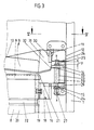
- Fig. 3 eine der Fig. 2 entsprechende Darstellung, jedoch bei in Öffnungsstellung befindlichem Deckel,
- Fig. 4 den Schnitt gemäß Linie IV-IV in Fig. 2,
- Fig. 5 den Schnitt gemäß Linie V-V in Fig. 3,
- Fig. 6 den Drehschaltnocken in perspektivischer Einzeldarstellung,
- Fig. 7 die Unteransicht hierzu,
- Fig.8-10 eine Bewegungsstudie unter Verdeutlichung einer Ausweichbewegung bei nicht funktionsgerechter Ausrichtung des Drehschaltnockens bzw. der Steuerplatte.
- Der die erfindungsgemäße Steuereinrichtung aufweisende Küchenschrank besitzt die beiden seitlichen Schrankwände 1, 2, eine Rückwand 3, die Decke 4 sowie einen Boden 5.
- Die Frontöffnung des Küchenschrankes wird über eine nicht näher dargestellte vertikale Blende verschlossen, welche sich unmittelbar oberhalb des Bodens 5 in einen schienengeführten Boden 6 fortsetzt. Die parallel ausgerichtet im unteren Bereich der Schrankwände 1 und 2 angeschlagenen Schienenführungen sind mit 7 bezeichnet. Den Schiebeendanschlag bildet die Rückwand.
- Der schienengeführte Boden 6 trägt einen Abfalleimer 8. Dessen obenliegender Öffnungsquerschnitt 9 ist bei in die Schließstellung getretener Blende durch einen Deckel 10 verschlossen. Es handlet sich um einen Klappdeckel. Letzterer sitzt an einer ortsfesten, horizontal ausgerichteten Achse 11 eines Trägers 12. Dieser folglich im Innenraum des Küchenschrankes verbleibende Deckel wird beim Vorfahren des Abfalleimers in die Öffnungsstellung und beim Zurückfahren desselben in die Schließstellung gesteuert. Die entsprechende Steuereinrichtung ist als Ganzes mit 13 bezeichnet. Sie besteht aus einem räumlich unterhalb der Deckel-Schwenkachse 11 liegenden, als Drehschaltnocken 14 ausgebildeten Stößel. Der Drehschaltnocken tritt in zwei Schaltstellungen und erstreckt sich in der Horizontalen. Seine Achse x-x ist vertikal ausgerichtet.
- Seinen Drehantrieb erhält der Drehschaltnocken 14 über eine in axialem Abstand unterhalb des Drehschaltnockens 14 sitzende, fest mit letzterem verbundene Steuerplatte 15. Auch diese ist horizontal ausgerichtet und erstreckt sich als segmentartiger Körper in den Bewegungsbereich eines Mitnehmers 16. Letzterer tritt auf einer Teillänge der Aus- bzw. Einfahrbewegung des Abfalleimers 8 formschlüssig in einen Schlitz 17 der Steuerplatte 15 ein. Die periphere Fangöffnung des Schlitzes 17 ist schon durch Verrunden der Schlitzenden, d. h. der Schlitzflanken 17' und 17" leicht trichterartig geweitet. Außerdem divergieren die Schlitzflanken nach außen hin noch, so daß eine dem Abwälzerfordernis Rechnung tragende Struktur vorliegt (praktisch einem Zahnradeingriff vergleichbar).
- Gebildet ist der Mitnehmer von einem U-förmigen Bauteil, wie es sich besonders deutlich aus den Fig. 4 und 5 ergibt. Den eigentlichen Schaltfinger des Mitnehmers formt der der Rückwand 3 des Küchenschrankes näherliegende U-Schenkel 18, dessen vertikale, gegen die befestigungsseitige Schrankwand 1 weisende Stirnfläche ebenfalls quergerundet ist, und zwar die Außenecke. Zur Befestigung des Mitnehmers 16 ist der Steg des U-förmigen Bauteiles herangezogen. Durch diesen treten Befestigungsmittel in Form von Halteschrauben 19 hindurch, welche den Mitnehmer entweder unmittelbar in Nähe des oberen Eimerrandes 21 festlegen oder, wie beim Ausführungsbeispiel bevorzugt, an einer den Abfalleimer 8 tragenden Winkelsäule 20, welche von der Oberseite des schienengeführten Bodens 6 ausgeht. Die Befestigung kann über eine den Winkelraum bodenseitig ausfüllenden Flanschplatte erfolgen, die Durchbrechungen für Befestigungsschrauben aufweist (nicht näher dargestellt). Der Abfalleimer 8 besitzt lang rechteckigen Grundriß, wobei die Eckzonen gerundet sind. Die Zuordnung des Abfalleimers 8 erfolgt durch Aufstülpen seines entsprechend umgekümpelten Randes 21 auf den oberen Bereich des Winkelprofils der Säule 20. Die Eigenlast und, unterstützend auch die Füllast, sichern die diesbezügliche vertikale Steckzuordnung. Quersicken 22 verleihen der Winkelsäule 20 trotz geringer Wandungsdicke eine hohe innere Stabilität und Tragfähigkeit.
- Verbunden sind die beiden stößelbildenden Steuerteile, nämlich der Drehschaltnocken 14 und die Steuerplatte 15 durch ein eine Nabe bildendes Röhrchen 23, welches oben die Oberseite des Drehschaltnockens 14 und unten die Unterseite der Steuerplatte 15 geringfügig überragt, so daß diese Seiten nicht auf den durch abgewinkelte Zungen des Trägers 12 gebildeten Lagerlappen 24 schleift, sondern nur die wesentlich flächenkleinere Stirnringzone des Röhrchens 23. Die eigentliche Achse bildet ein von oben her die Lagerlappen 24 sowie die Nabenhöhlung 23' des Röhrchens 23 zentral durchsetzender Bolzen 25. Letzterer bestizt oberseitig eine sein Durchrutschen verhindernde nietkopfartige Verdickung 26. Das noch etwas aus dem unteren Lagerlappen 24 des Trägers vorstehende Ende des Bolzens 25 nimmt ein Hütchen 27 auf. Dieses ist klemmend gehalten. Es kann sich um ein solches aus Gummi oder weichelastischem Kunststoff handeln.
- Wie bspw. Fig. 2 entnehmbar, ist der vertikale Abstand zwischen den Innenseiten der Lagerlappen 24 größer bemessen als die Gesamtlänge des nabenbildenden Röhrchens 23. Diese Abstandsdifferenz führt zu einem freien Hubweg y. Dieser entspricht mindestens der in der Vertikalen gemessenen Dicke der Steuerplatte 15, so daß diese bei nicht funktionsgerechter Grundstellung in vertikaler Richtung nach oben ausweichen kann. Die Steuerplatte besitzt dazu eine im Bewegungsbereich des Mitnehmers 16 liegende Aushebe-Schrägflanke 28, und zwar im Rücken der der Blende augewandten Schlitzflanke 17'.
- Drehschaltnocken 14 und Steuerplatte 15 sind für den Einsatz als Links- oder Rechtsanschlag des Trägers 12 umwende-symmetrisch gestaltet. Die Symmetrie-Ebene E-E ergibt sich aus Fig. 7. Sie schneidet die Achse x-x. Die Schlitze erstrecken sich in einem spitzen Winkel Alpha von ca. 45° zu dieser Ebene, wobei der Scheitelpunkt des spitzen Winkels kurz vor der Mantelfläche des Röhrchens liegt und die Linienverlängerung diese Mantelfläche auf der anderen Seiteder Ebene E-E tangiert. Die symmetrische Gestalt der steuerplatte läßt sich zur Bildung von Begrenzungs-Endanschlägen der beiden Schaltstellungen nutzen. Der segmentartige Grundriß erstreckt sich nahezu über einen Viertelkreis, so daß unter Berücksichtigung der gestreckten Ausrichtung des Trägers, in dessen unmittelbarer Nähe die Drehstößel-Verachsung vorgenommen ist, ein Drehwinkelbereich von ca. 90° vorliegt, der Schlitz 17 also nicht aus dem Fangbereich des Mitnehmers geraten kann. In Schließstellung des Deckels 10 fährt die eine Flügelkante F 1 gegen die befestigungsseitige Grundplatte des Trägers 12 und in der Öffnungsstellung des Deckels der andere Flügel F 2 gegen einen dem genannten Träger noch zugeordneten Gegenanschlag 29 in Form eines Böckchens 29'. Letzteres ist, in vertikaler Richtung gesehen, von einer solchen Höhe, daß ein Übergreifen der bei Notfunktion ausweichenden Steuerplatte 15 nicht möglich ist.
- Wie Fig. 2 deutlich entnehmbar, besteht der Träger 12 aus einem U-förmigen Grundprofil, dessen Steg zur wandseitigen Befestigung herangezogen ist. Teile der horizontal in den Schrankraum weisenden Schenkel formen die bereits erwähnten Lagerlappen 24, darüber hinaus aber auch durch quer dazu liegende, freigeschnittene Lappen die Lageraugen 30 für die deckelscharnierbildende Achse 11.
- Der Scharnierbereich des Deckels 10 formt einen nach unten hin offenen Kasten 31. Dessen der Schrankwand 1 zugewandte vertikale Wand 32, d. h. ihr unterhalb der Achse 11 liegender Abschnitt arbeitet steuerungstechnisch mit der Stoßfläche 33 des Drehschaltnockens 14 zusammen.
- Diese Stoßfläche 33 setzt sich aus zwei, im Falle der spiegelsymmetrischen Ausgestaltung insgesamt aus drei Steuerflächenabschnitten zusammen, nämlich einem sich in größerem radialen Abstand zur Vertikalachse x-x erstreckenden Stoßflächenabschnitt 33' und zwei beiderseits dazu im stumpfen Winkel Beta anschließende Stoßflächenabschnitte 33" geringeren radialen Abstands zur genannten Achse. Der Restumfang ist kreisrund. In Schließstellung des Deckels 10 (vergl. Fig. 2 und 4) befindet sich der in geringerem Abstand zur Achse x-x liegende Stoßflächenabschnitt 33" in Anlage zur Wand 32 des Deckels, während zum Anheben des Deckels 10 in seine leichte Hochklapplage (vergl. Fig. 3) der in größerem Abstand zur genannten Achse stehende Stoßflächenabschnitt 33' in Funktion tritt. Zufolge der möglichst nahen Anrodnung des Drehschaltnockens zur Scharnierstelle, kommt man mit einer relativ geringen, radialen Nockenhöhe aus.
- Die Funktion ist, kurz zusammengefaßt, wie folgt: Durch Ziehen an der nicht dargestellten Blende fährt der den Abfalleimer 8 tragende Boden 6 in Richtung des Pfeiles A (Fig. 4) aus dem Inneren des Schrankes aus, bis sein Öffnungsquerschnitt völlig außerhalb der Grundrißebene des Schrankes liegt, so daß der Abfalleimer unter Benutzung seines Tragbügels 34 angehoben werden kann. Gleich zu Anfang der Ausfahrbewegung bewirkt der Mitnehmer 16 unter Drehen der Steuerplatte 15 das Verschwenken des Drehschaltnockens 14 derart, daß seine maximal vorstehender Abschnitt, nämlich der Stoßflächenabschnitt 33' gegen die Wand 32 des Deckels fährt, um diesen in Richtung des Pfeiles B zu verschwenken.
- Das Einführen des Eimers in den Schrank geschieht in umgekehrter Reihenfolge.
- Nimmt der Drehstößel bei vorgezogenem Boden 6 eine nicht funktionsgerechte Lage ein, bspw. aufgrund von Berührungen bei Reinigungsmaßnahmen im Schrankinneren, so daß der Flügel F 1 gegen den Grund des Trägers getreten ist, so bewirkt die Schrägflanke 28 ein Hocksteuern des Drehstößels. Der Mitnehmer 16 unterläuft schadfrei die Steuerplatte 15 und der Schlitz 17 fällt ein.
- Der verschiebliche Boden 6 kann mehrere zugleich von einem Deckel überfangene Abfalleimer 8 tragen, bspw. um den Abfall in Wertabfall und üblichen Abfall zu sortieren.
- Alle in der Beschreibung erwähnten und in der Zeichnung dargestellten neuen Merkmale sind erfindungswesentlich, auch soweit sie in den Ansprüchen nicht ausdrücklich beansprucht sind.
Claims (6)
Priority Applications (1)
| Application Number | Priority Date | Filing Date | Title |
|---|---|---|---|
| AT86109936T ATE50227T1 (de) | 1985-10-09 | 1986-07-19 | Schienengefuehrter abfalleimer. |
Applications Claiming Priority (2)
| Application Number | Priority Date | Filing Date | Title |
|---|---|---|---|
| DE3535969A DE3535969C1 (de) | 1985-10-09 | 1985-10-09 | Schienengefuehrter Abfalleimer |
| DE3535969 | 1985-10-09 |
Publications (3)
| Publication Number | Publication Date |
|---|---|
| EP0218025A2 true EP0218025A2 (de) | 1987-04-15 |
| EP0218025A3 EP0218025A3 (en) | 1988-11-30 |
| EP0218025B1 EP0218025B1 (de) | 1990-02-07 |
Family
ID=6283114
Family Applications (1)
| Application Number | Title | Priority Date | Filing Date |
|---|---|---|---|
| EP86109936A Expired - Lifetime EP0218025B1 (de) | 1985-10-09 | 1986-07-19 | Schienengeführter Abfalleimer |
Country Status (3)
| Country | Link |
|---|---|
| EP (1) | EP0218025B1 (de) |
| AT (1) | ATE50227T1 (de) |
| DE (2) | DE3535969C1 (de) |
Cited By (2)
| Publication number | Priority date | Publication date | Assignee | Title |
|---|---|---|---|---|
| EP0443601B1 (de) * | 1990-02-22 | 1994-04-13 | Fritz Hakemann | Vorrichtung zur Aufnahme von insbesondere in Haushalt, Gastronomie und dergleichen anfallendem Abfall |
| WO1995029110A1 (de) * | 1994-04-25 | 1995-11-02 | Westermann Kg | Abfallsammler |
Family Cites Families (1)
| Publication number | Priority date | Publication date | Assignee | Title |
|---|---|---|---|---|
| DE3304327C2 (de) * | 1983-02-09 | 1984-11-29 | Hailo-Werk Rudolf Loh Gmbh & Co Kg, 6342 Haiger | Vorrichtung zum Öffnen und Schließen des Deckels für einen Abfalleimer innerhalb eines Schrankes |
-
1985
- 1985-10-09 DE DE3535969A patent/DE3535969C1/de not_active Expired
-
1986
- 1986-07-19 AT AT86109936T patent/ATE50227T1/de not_active IP Right Cessation
- 1986-07-19 EP EP86109936A patent/EP0218025B1/de not_active Expired - Lifetime
- 1986-07-19 DE DE8686109936T patent/DE3668871D1/de not_active Expired - Fee Related
Cited By (2)
| Publication number | Priority date | Publication date | Assignee | Title |
|---|---|---|---|---|
| EP0443601B1 (de) * | 1990-02-22 | 1994-04-13 | Fritz Hakemann | Vorrichtung zur Aufnahme von insbesondere in Haushalt, Gastronomie und dergleichen anfallendem Abfall |
| WO1995029110A1 (de) * | 1994-04-25 | 1995-11-02 | Westermann Kg | Abfallsammler |
Also Published As
| Publication number | Publication date |
|---|---|
| EP0218025B1 (de) | 1990-02-07 |
| ATE50227T1 (de) | 1990-02-15 |
| DE3535969C1 (de) | 1986-12-18 |
| EP0218025A3 (en) | 1988-11-30 |
| DE3668871D1 (de) | 1990-03-15 |
Similar Documents
| Publication | Publication Date | Title |
|---|---|---|
| EP0377703B1 (de) | Beschlag für ein mehrere übereinander angeordnete schubkästen aufweisendes möbel | |
| AT413630B (de) | Ausziehsperreinrichtung | |
| DE102015002945A1 (de) | Schublade, Möbelstück mit Schublade und Verfahren zum Öffnen einer Schublade | |
| EP3941310B1 (de) | Schiebe-schwenkmechanik für eine ablage eines möbels oder haushaltsgerätes und möbel bzw. haushaltsgerät | |
| DE3215572A1 (de) | Oberschrank mit einem absenkbaren einsatzkorb | |
| EP0361001B1 (de) | Schlosshaken | |
| EP0218025B1 (de) | Schienengeführter Abfalleimer | |
| DE102017211203B4 (de) | Hebesystem für eine Haushaltsgeschirrspülmaschine oder ein Möbel | |
| DE2259273A1 (de) | Vorrichtung zum umsetzen von stueckgut aus einer rollenbahn | |
| EP0379475B1 (de) | Kippvorrichtung zum Entleeren eines Müllbehälters, insbesondere für Müllfahrzeuge | |
| DE4314062A1 (de) | Handbetätigbare Presse | |
| DE3040479A1 (de) | Behaelter | |
| DE2430737C3 (de) | Drehtisch | |
| DE10147782A1 (de) | Betätigungsgetriebe, insbesondere Schloss für einen Treibstangenbeschlag sowie Treibstangenbeschlag mit einem solchen Betätigungsgetriebe | |
| EP0501111A1 (de) | Faltbare Tür | |
| DE2937440C2 (de) | Haushaltgerät, insbesondere Geschirrspülmaschine, mit einer Tür und einer zweiteiligen Vorsatzplatte | |
| EP3089890B1 (de) | Abdeckvorrichtung eines kofferraumfachs eines kraftfahrzeugs | |
| EP0536547B1 (de) | Wagenheber | |
| DE8804437U1 (de) | Vorrichtung für eine mittels eines Motors schließbare Tür od. dgl. | |
| DE3322292C2 (de) | Sicherheitsschalter mit Fehlschließsicherung | |
| EP1050490A1 (de) | Container mit Schwerkraftschloss | |
| EP0004381B1 (de) | Container-Befestigungsvorrichtung | |
| DE2054400B1 (de) | Kombinierter Bett-Nachttisch mit einem an einer Seite angeordneten Bett-Tischteil und mit einer durchschiebbaren Schublade | |
| EP1019604B1 (de) | Verschlussvorrichtung mit horizontaler handhabe | |
| DE2240001C2 (de) | Türverriegelung für Fahrzeug-Aufbauten und Container |
Legal Events
| Date | Code | Title | Description |
|---|---|---|---|
| PUAI | Public reference made under article 153(3) epc to a published international application that has entered the european phase |
Free format text: ORIGINAL CODE: 0009012 |
|
| AK | Designated contracting states |
Kind code of ref document: A2 Designated state(s): AT BE CH DE FR GB IT LI LU NL SE |
|
| PUAL | Search report despatched |
Free format text: ORIGINAL CODE: 0009013 |
|
| AK | Designated contracting states |
Kind code of ref document: A3 Designated state(s): AT BE CH DE FR GB IT LI LU NL SE |
|
| 17P | Request for examination filed |
Effective date: 19881103 |
|
| 17Q | First examination report despatched |
Effective date: 19890721 |
|
| GRAA | (expected) grant |
Free format text: ORIGINAL CODE: 0009210 |
|
| AK | Designated contracting states |
Kind code of ref document: B1 Designated state(s): AT BE CH DE FR GB IT LI LU NL SE |
|
| REF | Corresponds to: |
Ref document number: 50227 Country of ref document: AT Date of ref document: 19900215 Kind code of ref document: T |
|
| ET | Fr: translation filed | ||
| REF | Corresponds to: |
Ref document number: 3668871 Country of ref document: DE Date of ref document: 19900315 |
|
| GBT | Gb: translation of ep patent filed (gb section 77(6)(a)/1977) | ||
| ITF | It: translation for a ep patent filed | ||
| PLBE | No opposition filed within time limit |
Free format text: ORIGINAL CODE: 0009261 |
|
| STAA | Information on the status of an ep patent application or granted ep patent |
Free format text: STATUS: NO OPPOSITION FILED WITHIN TIME LIMIT |
|
| 26N | No opposition filed | ||
| ITTA | It: last paid annual fee | ||
| PGFP | Annual fee paid to national office [announced via postgrant information from national office to epo] |
Ref country code: SE Payment date: 19920616 Year of fee payment: 7 |
|
| PGFP | Annual fee paid to national office [announced via postgrant information from national office to epo] |
Ref country code: LU Payment date: 19920715 Year of fee payment: 7 |
|
| EPTA | Lu: last paid annual fee | ||
| PG25 | Lapsed in a contracting state [announced via postgrant information from national office to epo] |
Ref country code: LU Free format text: LAPSE BECAUSE OF NON-PAYMENT OF DUE FEES Effective date: 19930719 |
|
| PG25 | Lapsed in a contracting state [announced via postgrant information from national office to epo] |
Ref country code: SE Effective date: 19930720 |
|
| EUG | Se: european patent has lapsed |
Ref document number: 86109936.4 Effective date: 19940210 |
|
| PGFP | Annual fee paid to national office [announced via postgrant information from national office to epo] |
Ref country code: CH Payment date: 19960618 Year of fee payment: 11 |
|
| PGFP | Annual fee paid to national office [announced via postgrant information from national office to epo] |
Ref country code: AT Payment date: 19960711 Year of fee payment: 11 |
|
| PGFP | Annual fee paid to national office [announced via postgrant information from national office to epo] |
Ref country code: BE Payment date: 19960911 Year of fee payment: 11 |
|
| PG25 | Lapsed in a contracting state [announced via postgrant information from national office to epo] |
Ref country code: AT Free format text: LAPSE BECAUSE OF NON-PAYMENT OF DUE FEES Effective date: 19970719 |
|
| PG25 | Lapsed in a contracting state [announced via postgrant information from national office to epo] |
Ref country code: LI Free format text: LAPSE BECAUSE OF NON-PAYMENT OF DUE FEES Effective date: 19970731 Ref country code: CH Free format text: LAPSE BECAUSE OF NON-PAYMENT OF DUE FEES Effective date: 19970731 Ref country code: BE Free format text: LAPSE BECAUSE OF NON-PAYMENT OF DUE FEES Effective date: 19970731 |
|
| BERE | Be: lapsed |
Owner name: WESTERMANN K.G. Effective date: 19970731 |
|
| REG | Reference to a national code |
Ref country code: CH Ref legal event code: PL |
|
| REG | Reference to a national code |
Ref country code: GB Ref legal event code: IF02 |
|
| PGFP | Annual fee paid to national office [announced via postgrant information from national office to epo] |
Ref country code: FR Payment date: 20020705 Year of fee payment: 17 |
|
| PGFP | Annual fee paid to national office [announced via postgrant information from national office to epo] |
Ref country code: NL Payment date: 20020709 Year of fee payment: 17 Ref country code: GB Payment date: 20020709 Year of fee payment: 17 |
|
| PG25 | Lapsed in a contracting state [announced via postgrant information from national office to epo] |
Ref country code: GB Free format text: LAPSE BECAUSE OF NON-PAYMENT OF DUE FEES Effective date: 20030719 |
|
| PG25 | Lapsed in a contracting state [announced via postgrant information from national office to epo] |
Ref country code: NL Free format text: LAPSE BECAUSE OF NON-PAYMENT OF DUE FEES Effective date: 20040201 |
|
| GBPC | Gb: european patent ceased through non-payment of renewal fee |
Effective date: 20030719 |
|
| PG25 | Lapsed in a contracting state [announced via postgrant information from national office to epo] |
Ref country code: FR Free format text: LAPSE BECAUSE OF NON-PAYMENT OF DUE FEES Effective date: 20040331 |
|
| NLV4 | Nl: lapsed or anulled due to non-payment of the annual fee |
Effective date: 20040201 |
|
| REG | Reference to a national code |
Ref country code: FR Ref legal event code: ST |
|
| PGFP | Annual fee paid to national office [announced via postgrant information from national office to epo] |
Ref country code: DE Payment date: 20040706 Year of fee payment: 19 |
|
| PG25 | Lapsed in a contracting state [announced via postgrant information from national office to epo] |
Ref country code: IT Free format text: LAPSE BECAUSE OF NON-PAYMENT OF DUE FEES;WARNING: LAPSES OF ITALIAN PATENTS WITH EFFECTIVE DATE BEFORE 2007 MAY HAVE OCCURRED AT ANY TIME BEFORE 2007. THE CORRECT EFFECTIVE DATE MAY BE DIFFERENT FROM THE ONE RECORDED. Effective date: 20050719 |
|
| PG25 | Lapsed in a contracting state [announced via postgrant information from national office to epo] |
Ref country code: DE Free format text: LAPSE BECAUSE OF NON-PAYMENT OF DUE FEES Effective date: 20060201 |