EP0219120B1 - Système de communication à deux fils - Google Patents
Système de communication à deux fils Download PDFInfo
- Publication number
- EP0219120B1 EP0219120B1 EP86114276A EP86114276A EP0219120B1 EP 0219120 B1 EP0219120 B1 EP 0219120B1 EP 86114276 A EP86114276 A EP 86114276A EP 86114276 A EP86114276 A EP 86114276A EP 0219120 B1 EP0219120 B1 EP 0219120B1
- Authority
- EP
- European Patent Office
- Prior art keywords
- digital
- communication
- process variable
- transmitting unit
- path
- Prior art date
- Legal status (The legal status is an assumption and is not a legal conclusion. Google has not performed a legal analysis and makes no representation as to the accuracy of the status listed.)
- Expired - Lifetime
Links
- 238000004891 communication Methods 0.000 title claims description 126
- 238000000034 method Methods 0.000 claims description 99
- 230000008569 process Effects 0.000 claims description 85
- 230000005540 biological transmission Effects 0.000 claims description 74
- 230000008859 change Effects 0.000 claims description 14
- 230000004044 response Effects 0.000 claims description 4
- 230000000737 periodic effect Effects 0.000 claims 3
- 230000003213 activating effect Effects 0.000 claims 1
- 238000001514 detection method Methods 0.000 claims 1
- 230000000415 inactivating effect Effects 0.000 claims 1
- 238000010586 diagram Methods 0.000 description 7
- 238000006243 chemical reaction Methods 0.000 description 5
- 239000002131 composite material Substances 0.000 description 2
- 230000000694 effects Effects 0.000 description 2
- 230000004075 alteration Effects 0.000 description 1
- 230000001447 compensatory effect Effects 0.000 description 1
Images


Classifications
-
- G—PHYSICS
- G08—SIGNALLING
- G08C—TRANSMISSION SYSTEMS FOR MEASURED VALUES, CONTROL OR SIMILAR SIGNALS
- G08C19/00—Electric signal transmission systems
- G08C19/02—Electric signal transmission systems in which the signal transmitted is magnitude of current or voltage
-
- H—ELECTRICITY
- H04—ELECTRIC COMMUNICATION TECHNIQUE
- H04B—TRANSMISSION
- H04B3/00—Line transmission systems
- H04B3/54—Systems for transmission via power distribution lines
- H04B3/548—Systems for transmission via power distribution lines the power on the line being DC
-
- H—ELECTRICITY
- H04—ELECTRIC COMMUNICATION TECHNIQUE
- H04L—TRANSMISSION OF DIGITAL INFORMATION, e.g. TELEGRAPHIC COMMUNICATION
- H04L5/00—Arrangements affording multiple use of the transmission path
- H04L5/14—Two-way operation using the same type of signal, i.e. duplex
- H04L5/16—Half-duplex systems; Simplex/duplex switching; Transmission of break signals non-automatically inverting the direction of transmission
-
- H—ELECTRICITY
- H04—ELECTRIC COMMUNICATION TECHNIQUE
- H04B—TRANSMISSION
- H04B2203/00—Indexing scheme relating to line transmission systems
- H04B2203/54—Aspects of powerline communications not already covered by H04B3/54 and its subgroups
- H04B2203/5404—Methods of transmitting or receiving signals via power distribution lines
- H04B2203/5408—Methods of transmitting or receiving signals via power distribution lines using protocols
-
- H—ELECTRICITY
- H04—ELECTRIC COMMUNICATION TECHNIQUE
- H04B—TRANSMISSION
- H04B2203/00—Indexing scheme relating to line transmission systems
- H04B2203/54—Aspects of powerline communications not already covered by H04B3/54 and its subgroups
- H04B2203/5429—Applications for powerline communications
- H04B2203/5458—Monitor sensor; Alarm systems
-
- H—ELECTRICITY
- H04—ELECTRIC COMMUNICATION TECHNIQUE
- H04B—TRANSMISSION
- H04B2203/00—Indexing scheme relating to line transmission systems
- H04B2203/54—Aspects of powerline communications not already covered by H04B3/54 and its subgroups
- H04B2203/5462—Systems for power line communications
- H04B2203/547—Systems for power line communications via DC power distribution
Definitions
- the present invention relates to a two-wire communication system, and in particular to a communication system suitable to a data communication system or the like between field devices such as terminal process variable transmitters and a control computer of a conventional analog control system used in a plant as well as a present and future digital control system.
- analog data transmission system As a two-wire data transmission or communication system for industrial instruments such as process variable transmitters, conventional analog data transmission system is known.
- the transmitter controls the current in a range of 4 to 20 mA.
- a system as described in Japanese Patent Unexamined Publication No. 85469/83 is known.
- digital data and analog data are alternately transmitted.
- the digital data communication consists of instructions for setting and adjusting transmitter functions sent from a communication unit to transmitters and answers sent from the transmitter to the communication unit. After the analog data transmission state is replaced by the digital data transmission state, a predetermined delay is introduced and then the analog data transmission state is resumed.
- This system is effective when a user adjusts and sets the transmitter function in a communication system of analog data transmission.
- the base state of this system is the analog data transmission state.
- the system for transmitting the process variable signal as digital data from a transmitter to a receiver or a high rank computer is not described.
- the communication unit of the above described system is susceptible to external disturbance or a change in voltage of the power supply because the communication unit is connected in parallel to the power supply, a resistor and a transmitter. Further, the receiver is connected in parallel to a resistor and is different from the communication unit in connection position. This results in lack of uniformity in view of interface to a high rank system in the future.
- An object of the present invention is to provide a communication system which makes possible replacing process variable transmitters in a conventional analog control system or installing process variable transmitters in a new analog control system. This object is achieved with a communication system according to claim 1. Remotely setting and adjusting the transmitter function by the communication unit in the above described system makes it possible for the control computer to control as far as terminals and facilitates digitization of the system.
- the present invention is based upon a concept that the future communication system for the process variable transmitter will be transferred from the analog data transmission system to a digital data transmission system facilitating transmission of higher precision, higher reliability and higher degree of multiplex.
- an analog data transmission state applicable to a conventional analog control system, a digital data transmission state applicable to a digital control system, and a digital communication state making possible remote setting and adjustment from a high rank computer through a communication unit or an interface are provided, and transfer from both transmission states to the digital communication state is permitted.
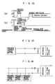
- Fig. 1 shows a block diagram which is an embodiment of a communication system according to the present invention.
- a process variable transmitter 1 is supplied with power from external power supply 5 through a resistor 4 having a value R L .
- a current I T forms the output signal of the process variable transmitter 1.
- a receiver 2 or a communication unit 3 is connected in parallel to a resistor 4. Under this state, power is supplied from the power supply to the process variable transmitter by using a transmission line 6. At the same time, data communication is conducted between the process variable transmitter and the communication unit, and data are transmitted from the process variable transmitter to the receiver.
- the terminal voltage and output current of the process variable transmitter 1 are represented by V T and I T , respectively.
- the terminal voltage of the resistor (R L ) 4 and the output current of the communication unit 3 are represented by V R and I C , respectively.
- the basic function of each block will now be described.
- the process variable transmitter has constant current characteristics and operates with a current of 4 mA derived through the transmission line.
- the process variable transmitter has analog data transmission function and digital data transmission/receiving function.
- the process variable such as pressure and temperature undergoes compensation processing in a microprocessor included in the process variable transmitter 1.
- the signal thus converted into a suitable form is transmitted as data through the transmission line.
- the process variable transmitter 1 receives digital data transmitted from the communication unit to process the digital data in the above described microprocessor and answers with digital data.
- the receiver is an analog data receiver or a digital data receiver and receives and indicates data. These are selected and set by the user.
- the communication unit has analog data receiving function, digital data transmitting/receiving function, data setting function, data indication function, and function for altering the communication state of the process variable transmitter.
- the whole system shown in Fig. 1 is entirely controlled by the command of the operator through the communication unit. If the system is directly connected to a high rank computer rather than the communication unit in the future, the system is controlled by the high rank computer.
- the analog data transmission state of (1) will now be described by referring to Fig. 2.
- the process variable transmitter transmits analog data by controlling the output current I T in the range of 4 to 20 mA in response to the process variable.
- the output current I T is transmitted through the transmission line and undergoes I/V conversion by the resistor R L to be detected by the receiver.
- Fig. 2 shows I T and V R as functions of time. Values and can be represented as: This state is the same as that of the conventional analog data transmission system and will not be described in detail.
- Data representing one process variable, instruction or answer data is treated as one data block (text) having a series of characters STX, CMD, data and ETX.
- the character STX is a transmission control character for indicating the beginning of the text.
- the character CMD indicates the kind of data.
- Characters D1 to D n are transmission data characters.
- the characters ETX is a transmission control character for indicating the termination of the text.
- Fig. 4 shows the bit structure of each character. This data format conforms to JISC 6220 and its detailed description will be omitted.
- Transmission of digital data is effected by controlling the output currents I T and I C in the process variable transmitter 1 and the communication unit 3, respectively.
- Digital data are transmitted by changing the current in pulse form so that the digital data "1" and "0" may correspond respectively to I min and I max in Fig. 4, for example.
- Such change in current undergoes I/V conversion to be detected as change in voltage by the receiver 2 or the communication unit 3. That is to say, the change in output currents I T or I C is converted into a voltage change via one resistor (R L ) 4 connected in series with the transmission line.
- the change in output current I T is received as a change in V R by the receiver 2 or the communication unit 3.
- a change in output current I C is received as a change in V T by the process variable transmitter 1.
- serial data pulses are obtained.
- the process variable transmitter periodically transmits the process variable as digital data.
- the process variable transmitter transmits digital data by controlling the output current I T in a predetermined current range, say, 4 to 20 mA so that the digital data "1" and "0" may correspond to 4 mA and 20 mA, respectively. Since the minimum operation current necessary for the process variable transmitter is 4 mA, the minimum current of the digital current signal is 4 mA.
- One process variable is transmitted as one data block.
- Data blocks are transmitted one after another at a predetermined transmission period, say, 0.1 sec.
- each data block is received as a change in the terminal voltage V R across the resistor 4 by the receiver 2 or the communication unit 3, resulting in serial data pulses.
- the digital data transmission/receiving function of the process variable transmitter assumes the receiving state between blocks and assumes the transmission state during the transmission of each data block. By using this receiving state, combination with the communication state described later becomes possible.
- the output current I T is fixed at a preset value, say, 4mA.
- the communication unit 3 transmits the function setting and adjusting instruction of the process variable transmitter 1 to the process variable transmitter 1 by using one data block.
- the process variable transmitter 1 also transmits the answer to the above described instruction to the communication unit 3 by using a flow data block.
- the communication unit 3 transmits digital data by controlling the output current in a predetermined current range 0 to I Cl so that digital data "1" and "0" may correspond to 0 mA and I Cl , respectively.
- the instruction data block shown in Fig. 6(a) is received as a change in the terminal voltage V T of the process variable transmitter by the process variable transmitter 1 as shown in Fig.
- the process variable transmitter 1 conducts processing in obedience to the instruction data in the microprocessor thereof. And the process variable transmitter 1 transmits the answer data block as one data block to the communication unit 3 by using the same method as the above described transmission method of the digital data transmission state. Under this communication state, the communication function of the process variable transmitter 1 assumes the receiving state and waits for the instruction from the communication unit. At this time, I T is fixed at a predetermined current value, say, 4 mA.
- FIG. 1 A communication system having the analog data transmission state and a state comprising a combination of the digital data transmissions state and the digital communication state belonging to the three communication states will now be described together with an embodiment of a method for changing over between the two communication states.
- the analog data transmission state is the same as that described before by referring to Fig. 2.
- a method for altering the analog data transmission state will now be described by referring to Figs. 1, 7 and 8. Until time t1 of Fig.
- the process variable transmitter 1 assumes the conventional analog data transmission state, and V T is in a voltage range between and During a predetermined period t c starting from the time t1, a current I Cl is let flow from the communication unit 3 into the resistor 4 to keep V T in a voltage range between V T0 and The relationship between I T and V T under this state and the relationship between I T and V T before t1 will now be described by referring to Fig. 8.
- the process variable transmitter compares the relationship between I T and V T derived as the initial state beforehand with the actual value of V T . When the process variable transmitter has recognized that ⁇ V exceeds the threshold ⁇ V TH for a predetermined period, it terminates the analog data transmission state and resumes the combined state of the digital data transmission and digital communication.
- the transmission period of the process variable transmitter 1 is set by a timer, and process variable data blocks are transmitted in synchronism with the output of the timer.
- the communication unit 3 receives a data block from the process variable transmitter 1 and transmits an instruction data block in synchronism with the termination of the data block from the process variable transmitter 1.
- the communication unit transmits the instruction data block in synchronism with the termination of the data block.
- the interval between data transmitted by the process variable transmitter 1 must be sufficiently longer than the data length transmitted by the communication unit 3.
- the instruction data are transmitted by the method described before with reference to Fig. 6.
- the communication unit 3 transmits an instruction data block
- the communication function of the transmitter assumes the receiving state and the transmitter receives the instruction data block transmitted by the communication unit as described before by reference to Fig. 5.
- the microprocessor included in the process variable transmitter 1 effects processing depending upon the instruction, and transmits the answer data block instead of a process variable data block in synchronism with the transmission period of digital data.
- the transmission method at this time is the same as that described before with reference to Fig. 6. If the instruction from the communication unit 3 is not present thereafter, the process variable transmitter 1 transmits process variable data blocks again with the period T.
- FIG. 10 A method for altering the state comprising a combination of digital data transmission and digital communication will now be described by referring to Fig. 10.
- a state alteration instruction data block is transmitted as the instruction data block of Fig. 9 corresponds to Fig. 10.
- the data transmission/receiving method is the same as that described before by referring to Fig. 9.
- the communication state is transferred to the analog transmission state.
- Figs. 11 and 12 are respectively block diagrams showing the basic configuration of the process variable transmitter 1 and the communication unit 3 satisfying the above described three communication states and function of the embodiment. At first, the configuration and function of the process variable transmitter 1 as well as disposal to the embodiment will now be described by referring to Fig. 11.
- a plurality of process variables such as pressure, differential pressure and temperature are sensed by a composite sensor 7.
- An analog input supplied from the composite sensor 7 is selected by a directive from the input/output selector 10 and is amplified in a programmable amplifier 9 with a gain directed by the input/output selector 10.
- the data which have undergone A/D conversion in an A/D converter undergo compensatory arithmetic processing in an MPU 24 handling the overall operation of the process variable transmitter centering around the calculation and communication processing.
- the date thus arithmetically processed reaches a multiplexer 2 (MPX 2) 17 through an analog output circuit 13 including a D/A converter or through an MPU 24, serial interface, and a digital output circuit 16.
- MPX 2 multiplexer 2
- the MPX 2 17 selects data to be supplied to a current controller 18.
- the current controller 18 including a voltage-to-current conversion circuit controls the output current on the basis of the input.
- the digital input circuit 19 receives digital data transmitted from the communication unit 3 and supplies the digital data to a serial interface of an MPU 24.
- the input/output selector 10 functions to latch the directive from the MPU and output it.
- An EPROM 25 stores the characteristics data and program of compensation calculation therein.
- a timer 26 provides a predetermined operation period.
- the MPU 24 supplies data to the analog output circuit, and selects D2 as the input to the MPX 2 17 through the input/output selector.
- the change ⁇ V in terminal voltage of the process variable transmitter as shown in Figs. 7 and 8 is measured by periodically selecting an A4 input of the MPX 1 8 and applying A/D conversion to V T .
- the MPU 24 sends out data through the serial interface thereof and selects D1 as the input of the MPX 2 17 via the input/output selector 10.
- the directive from the operator is taken into an MPU 34 through a keyboard 38.
- the data constructed by the MPU on the basis of the directive arrive at a current controller 27 through the serial data interface of the MPU 34 and a digital output circuit 32.
- the current controller 27 including a voltage-to-current converter circuit controls the output current in response to its input.
- a digital input circuit 30 receives the digital data transmitted from the process variable transmitter and supplies its output to the serial interface of the MPU 34.
- An A/D converter 37 is supplied with the terminal voltage across the resistor 4 caused by the analog data transmitted from the process variable transmitter 1 and supplies the converted digital data to the MPU 34.
- a ROM 36 stores program therein and a timer 35 provides a predetermined operation period.
- An indicator 39 displays input data supplied from the operator and data transmitted from the process variable transmitter 1.
- the MPU 34 receives data through the A/D converter 37 and the timer 35 provides the receiving period.
- the process variable transmitter 1 assumes the digital data transmission state
- the MPU 34 receives data through the digital input circuit 30.
- the process variable transmitter 1 assumes the digital communication state
- data are sent out through the digital output circuit 32, and the answer data are received through the digital input circuit 30.
- the lead “Tx enable” is usually kept at the low level.
- the period t c is given by the timer.
- FIG. 13 a high rank system is connected to the process variable transmitter through an interface having the transmission/receiving function similar to that of the communication unit 3.
- Fig. 14 shows a system having a plurality of process variable transmitters connected to a two-wire transmission line in parallel. In this system, multiplex operation becomes possible under the digital data transmission state by applying the time division scheme to the transmission period shown in Fig. 5 and adding the address of each transmitter to the process variable data block.
- the process variable transmitter using the present two-wire communication method can be used for replacement in the conventional analog control system and can be easily adapted to the future digital control system. Further, in the conventional analog control system as well, the process variable transmitter can be remotely set and adjusted by altering the communication state. Since the communication unit is connected in parallel to the resistor, the data reception by the communication unit is not susceptible to variation in supply voltage and external disturbance. And both analog data and digital data can be received. If the signal produced when the state is transferred from the analog data transmission state to another state is a pulse signal, there is a possibility of erroneous operation due to disturbance noise. In the present system as shown in Figs. 7 and 8, however, there is not much possibility of erroneous operation. If the two-wire multiplexing as shown in Fig. 14 is used, the wiring process can be simplified and the cost can be reduced.
- the process variable transmitter according to the communication system of the present invention can be used in the conventional analog control system.
- the process variable transmitter can be easily maintained by using the digital communication state.
- the cost when the system is developed can be reduced.
- the digital data transmission state and digital communication state it is possible in the digital control system to collect data from all field terminal devices such as process variable transmitters to a central supervision room and supervise and manage the collected data there, resulting in an efficient digital control system.
- the process variable transmitter according to the communication system of the present invention is effective to communication whereby the output signal is derived while power is being supplied to a sensor.
Landscapes
- Engineering & Computer Science (AREA)
- Signal Processing (AREA)
- Computer Networks & Wireless Communication (AREA)
- Physics & Mathematics (AREA)
- General Physics & Mathematics (AREA)
- Power Engineering (AREA)
- Cable Transmission Systems, Equalization Of Radio And Reduction Of Echo (AREA)
- Arrangements For Transmission Of Measured Signals (AREA)
Claims (11)
- Système de communication à deux fils, comprenant:
une voie de transmission à deux fils (6);
une unité d'émission (1) possédant une caractéristique de courant constant et raccordée à une première extrémité de ladite voie et également raccordée de manière à recevoir un signal variable de processus;
un circuit série formé par le raccordement d'une résistance de charge (4) et d'une source d'énergie (5), ledit circuit série étant raccordé à l'autre extrémité de ladite voie de sorte que ladite résistance et ladite source d'énergie sont raccordées en série à l'unité d'émission par l'intermédiaire de ladite voie; et
une unité de communication (3);
dans lequel ladite unité d'émission comprend des moyens de traitement numérique pour traiter ledit signal variable de processus et envoyer, dans ladite voie, des blocs de signaux de courant numériques périodiques en tant que résultat dudit traitement, et des premiers moyens de communication numérique pour établir une communication numérique avec l'unité de communication par l'intermédiaire de la voie; et
dans lequel ladite unité de communication comprend des moyens pour recevoir lesdits blocs de signaux de courant numériques périodiques de la part de ladite unité d'émission et des seconds moyens de communication numérique pour établir une communication numérique avec ladite unité d'émission par l'intermédiaire de ladite voie,
caractérisé en ce que ladite unité de communication est branchée en parallèle avec ladite résistance. - Système de communication à deux fils selon la revendication 1, dans lequel l'un quelconque des moyens de traitement numérique et des premiers moyens de communication numérique peut fonctionner sélectivement en réponse à une communication émanant de l'unité de communication.
- Système de communication à deux fils selon la revendication 1, caractérisé en ce que ladite unité d'émission comprend en outre des moyens de traitement analogique pour traiter ledit signal variable de processus et pour envoyer un signal de courant analogique à ladite voie en tant que résultat dudit traitement, et ladite unité de communication comprend en outre des moyens pour recevoir ledit signal de courant analogique de la part de ladite unité d'émission.
- Système de communication à deux fils selon la revendication 3, dans lequel l'un quelconque des moyens de traitement analogique, des moyens de traitement numérique et des premiers moyens de communication peut fonctionner de façon sélective en réponse à une communication provenant de l'unité de communication.
- Système de communication à deux fils selon la revendication 4, dans lequel ladite unité de communication comprend des moyens pour produire une impulsion de courant ayant une amplitude et une durée prédéterminées pour modifier une tension développée aux bornes de ladite résistance par ladite unité d'émission, et dans lequel l'unité d'émission comprend des moyens répondant à la détection d'une variation de la tension aux bornes de ladite résistance pour désactiver les moyens de traitement analogique et activer soit les moyens de traitement numérique, soit les premiers moyens de communication numérique.
- Système de communication à deux fils selon les revendications 2 et 4, dans lequel lesdits seconds moyens de communication numérique comprennent des moyens pour envoyer, à la voie, un bloc de signaux de courant numériques à la suite de la réception d'un bloc de signaux de courant numériques de la part de ladite unité d'émission, les intervalles entre lesdits blocs de signaux de courant numériques périodiques délivrés par ladite unité d'émission étant d'une durée supérieure à celle du bloc de signaux de courant numériques délivré par ladite unité de communication.
- Système de communication à deux fils selon la revendication 6, dans lequel le bloc de signaux de courant numériques délivré par ladite unité de communication est intercalé entre les blocs de signaux de courant numériques délivrés par ladite unité d'émission.
- Système de communication à deux fils selon la revendication 1, caractérisé en ce que ladite unité de communication comprend en outre des moyens d'interface branchés en parallèle avec la résistance pour raccorder l'unité d'émission et un système à rang élevé par l'intermédiaire desdits moyens d'interface.
- Système de communication à deux fils selon la revendication 8, comprenant en outre au moins une unité supplémentaire d'émission de variables de processus raccordée à ladite première extrémité de ladite voie.
- Système de communication à deux fils selon la revendication 9, dans lequel une adresse est envoyée à chacune desdites unités d'émission de variables de processus.
- Système de communication à deux fils selon la revendication 9, dans lequel lesdites unités d'émission de variables de processus sont branchées en parallèle avec ladite voie.
Applications Claiming Priority (2)
| Application Number | Priority Date | Filing Date | Title |
|---|---|---|---|
| JP228699/85 | 1985-10-16 | ||
| JP60228699A JP2735174B2 (ja) | 1985-10-16 | 1985-10-16 | 2線式通信方法 |
Publications (3)
| Publication Number | Publication Date |
|---|---|
| EP0219120A2 EP0219120A2 (fr) | 1987-04-22 |
| EP0219120A3 EP0219120A3 (en) | 1988-11-17 |
| EP0219120B1 true EP0219120B1 (fr) | 1993-01-27 |
Family
ID=16880412
Family Applications (1)
| Application Number | Title | Priority Date | Filing Date |
|---|---|---|---|
| EP86114276A Expired - Lifetime EP0219120B1 (fr) | 1985-10-16 | 1986-10-15 | Système de communication à deux fils |
Country Status (5)
| Country | Link |
|---|---|
| US (1) | US4737787A (fr) |
| EP (1) | EP0219120B1 (fr) |
| JP (1) | JP2735174B2 (fr) |
| CN (1) | CN1004677B (fr) |
| DE (1) | DE3687621T2 (fr) |
Cited By (2)
| Publication number | Priority date | Publication date | Assignee | Title |
|---|---|---|---|---|
| DE10102791A1 (de) * | 2001-01-22 | 2002-08-01 | Ifm Electronic Gmbh | Elektrischer Messumformer |
| DE10113716A1 (de) * | 2001-03-19 | 2002-10-02 | Balluff Gmbh | Kommunikations-Schnittstelle für eine Wegmeßeinrichtung |
Families Citing this family (33)
| Publication number | Priority date | Publication date | Assignee | Title |
|---|---|---|---|---|
| US4818994A (en) * | 1987-10-22 | 1989-04-04 | Rosemount Inc. | Transmitter with internal serial bus |
| US5278543A (en) * | 1987-10-22 | 1994-01-11 | Rosemount Inc. | Transmitter with magnetic zero/span actuator |
| JPH0693684B2 (ja) * | 1989-03-03 | 1994-11-16 | 株式会社日立製作所 | フィールドセンサと通信器との通信方法およびその装置 |
| DE3921744A1 (de) * | 1989-07-01 | 1991-01-03 | Bayerische Motoren Werke Ag | Kommunikationsverfahren fuer einen einleitungs-datenbus von kraftfahrzeugen |
| JPH0650557B2 (ja) * | 1989-07-04 | 1994-06-29 | 株式会社日立製作所 | フィールド計器の通信方式 |
| JP3137643B2 (ja) * | 1989-10-02 | 2001-02-26 | ローズマウント インコーポレイテッド | 現場に設置される制御ユニット |
| JP2580343B2 (ja) | 1989-10-13 | 1997-02-12 | 株式会社日立製作所 | フィールド計器システム及びコミュニケータ |
| CA2049618A1 (fr) * | 1991-07-18 | 1993-01-19 | Christopher J. O'brien | Emetteur et controleur integres |
| CA2107519C (fr) * | 1992-10-05 | 2002-04-09 | Stephen George Seberger | Systeme et methode de communication |
| JP2882316B2 (ja) * | 1995-08-29 | 1999-04-12 | 株式会社デンソー | データ通信装置 |
| US5793754A (en) * | 1996-03-29 | 1998-08-11 | Eurotherm Controls, Inc. | Two-way, two-wire analog/digital communication system |
| DE19813700C2 (de) * | 1998-03-27 | 2003-03-27 | Samson Ag | Eingangsschaltung für ein Feldgerät |
| WO1999053627A1 (fr) | 1998-04-10 | 1999-10-21 | Chrimar Systems, Inc. Doing Business As Cms Technologies | Systeme de communication avec un equipement electronique sur un reseau |
| FR2781301B1 (fr) * | 1998-07-20 | 2000-09-08 | Alstom Technology | Boucle de courant du type 4-20 milliamperes ou 0-20 milliamperes comportant un circuit de test en parallele |
| US6351691B1 (en) | 1998-10-15 | 2002-02-26 | Micro Motion, Inc. | I/O signaling circuit |
| US20020149379A1 (en) * | 2000-01-12 | 2002-10-17 | Winfried Rauer | Electronic measuring device for detecting a process variable, in particular a radar or ultrasonic filling level measuring device, and a method for operating a measuring device of this type |
| DE10111263C2 (de) | 2001-03-09 | 2003-10-30 | Bosch Gmbh Robert | Schnittstellenbaustein |
| US7756917B2 (en) * | 2001-09-28 | 2010-07-13 | Baseline, Llc | Two wire communication apparatus and method |
| RU2259633C2 (ru) * | 2002-09-23 | 2005-08-27 | Овчинников Валерий Васильевич | Способ передачи дискретных электрических сигналов |
| US7191269B2 (en) * | 2003-07-30 | 2007-03-13 | Delphi Technologies, Inc. | Method for multiple sensors to communicate on a uni-directional bus |
| US7016741B2 (en) * | 2003-10-14 | 2006-03-21 | Rosemount Inc. | Process control loop signal converter |
| WO2005075944A1 (fr) * | 2004-01-28 | 2005-08-18 | Vega Grieshaber Kg | Dispositif d'alimentation pour capteurs de commutation a basse puissance d'un systeme modulaire |
| DE102006005334B4 (de) | 2006-02-07 | 2022-12-22 | Bayerische Motoren Werke Aktiengesellschaft | Verfahren zur Überwachung und/oder Steuerung oder Regelung der Spannung wenigstens einer Zellgruppe in einem Zellenverbund eines Energiespeichers sowie Zellgruppenlogik und Zentral-Logik zur Durchführung des Verfahrens |
| AU2009298996B2 (en) * | 2008-10-02 | 2014-11-20 | Hochiki Corporation | Transmission input circuit |
| US8248230B2 (en) * | 2009-02-20 | 2012-08-21 | Redwood Systems, Inc. | Smart power device |
| US8427300B2 (en) | 2009-02-20 | 2013-04-23 | Redwood Systems, Inc. | Transmission of power and data with frequency modulation |
| US8207635B2 (en) * | 2009-02-20 | 2012-06-26 | Redwood Systems, Inc. | Digital switch communication |
| US8058750B2 (en) * | 2009-05-14 | 2011-11-15 | Redwood Systems, Inc. | Discharge cycle communication |
| DE102011075836B4 (de) * | 2011-05-13 | 2013-02-21 | Continental Automotive Gmbh | Kommunikationssystem für eine Energiespeichervorrichtung für ein Kraftfahrzeug und Energiespeichervorrichtung für ein Kraftfahrzeug sowie Verfahren zum Betrieb des Kommunikationssystems |
| DE102012102672B4 (de) * | 2012-03-28 | 2016-11-03 | Austriamicrosystems Ag | Empfängerschaltung und Verfahren zum Empfang eines Eingangssignals sowie Lichtmodul mit einer derartigen Empfängerschaltung und Schaltungsanordnung |
| US9784791B2 (en) * | 2014-07-18 | 2017-10-10 | Intel Corporation | Apparatus and method to debug a voltage regulator |
| CN106161653B (zh) * | 2016-08-30 | 2022-11-15 | 北京华控技术有限责任公司 | 一种两线制变送器系统及其通信方法 |
| DE102016119548A1 (de) * | 2016-10-13 | 2018-04-19 | Endress+Hauser SE+Co. KG | Verfahren zur Datenübertragung zwischen einem Feldgerät der Automatisierungstechnik und einer Kommunikationsbox |
Family Cites Families (7)
| Publication number | Priority date | Publication date | Assignee | Title |
|---|---|---|---|---|
| US3959786A (en) * | 1975-06-03 | 1976-05-25 | Rochester Instrument Systems, Inc. | Isolated two-wire transmitter |
| US4339750A (en) * | 1980-08-20 | 1982-07-13 | Rosemount Inc. | Low power transmitter |
| US4520488A (en) * | 1981-03-02 | 1985-05-28 | Honeywell, Inc. | Communication system and method |
| CA1173927A (fr) * | 1981-11-02 | 1984-09-04 | Felix J. Houvig | Methode et systeme de communication |
| EP0101528B1 (fr) * | 1982-08-19 | 1989-11-08 | Honeywell Inc. | Systèmes analogiques de communication à deux fils |
| US4633217A (en) * | 1984-06-04 | 1986-12-30 | Yamatake Honeywell | Communication apparatus |
| US4607247A (en) * | 1985-08-12 | 1986-08-19 | The Babcock & Wilcox Company | On-line serial communication interface from a transmitter to a current loop |
-
1985
- 1985-10-16 JP JP60228699A patent/JP2735174B2/ja not_active Expired - Lifetime
-
1986
- 1986-10-15 CN CN86107097.6A patent/CN1004677B/zh not_active Expired
- 1986-10-15 DE DE8686114276T patent/DE3687621T2/de not_active Expired - Fee Related
- 1986-10-15 EP EP86114276A patent/EP0219120B1/fr not_active Expired - Lifetime
- 1986-10-16 US US06/919,764 patent/US4737787A/en not_active Expired - Lifetime
Cited By (4)
| Publication number | Priority date | Publication date | Assignee | Title |
|---|---|---|---|---|
| DE10102791A1 (de) * | 2001-01-22 | 2002-08-01 | Ifm Electronic Gmbh | Elektrischer Messumformer |
| DE10102791B4 (de) * | 2001-01-22 | 2004-04-15 | Ifm Electronic Gmbh | Elektrischer Meßumformer |
| DE10113716A1 (de) * | 2001-03-19 | 2002-10-02 | Balluff Gmbh | Kommunikations-Schnittstelle für eine Wegmeßeinrichtung |
| DE10113716C2 (de) * | 2001-03-19 | 2003-05-08 | Balluff Gmbh | Kommunikations-Schnittstelle für eine Wegmeßeinrichtung |
Also Published As
| Publication number | Publication date |
|---|---|
| DE3687621D1 (de) | 1993-03-11 |
| CN1004677B (zh) | 1989-06-28 |
| JPS6290049A (ja) | 1987-04-24 |
| DE3687621T2 (de) | 1993-06-03 |
| EP0219120A2 (fr) | 1987-04-22 |
| US4737787A (en) | 1988-04-12 |
| EP0219120A3 (en) | 1988-11-17 |
| CN86107097A (zh) | 1987-05-13 |
| JP2735174B2 (ja) | 1998-04-02 |
Similar Documents
| Publication | Publication Date | Title |
|---|---|---|
| EP0219120B1 (fr) | Système de communication à deux fils | |
| CA1293550C (fr) | Emetteur a ligne de transmission bifilaire | |
| US4633217A (en) | Communication apparatus | |
| US5420578A (en) | Integrated transmitter and controller | |
| EP0546855A1 (fr) | Circuit et module d'entrée/sortie à modes multiples, et système de commande de processus les utilisant | |
| US6307483B1 (en) | Conversion circuit for process control system | |
| EP0101528B1 (fr) | Systèmes analogiques de communication à deux fils | |
| IL64649A (en) | Nuclear reactor power supply system and method of controlling it | |
| JPH0467817B2 (fr) | ||
| US4422073A (en) | Combustible gas detection system | |
| EP0213767B1 (fr) | Dispositifs pour boucle de courant | |
| US3959786A (en) | Isolated two-wire transmitter | |
| JPH0693684B2 (ja) | フィールドセンサと通信器との通信方法およびその装置 | |
| EP0266553B1 (fr) | Système de transmission à deux fils | |
| HRP960492A2 (en) | Field bus signal transmission system | |
| US5673278A (en) | Method and apparatus for introducing diagnostic pulses into an analog signal generated by an instrument | |
| JPS62272399A (ja) | 差圧・圧力伝送器 | |
| Cobb | Control in the field with HART® communications | |
| SU734763A1 (ru) | Система дл контрол и управлени технологическими процессами | |
| JP3165069B2 (ja) | フィールドバス・システム及び仮想フィールド機器 | |
| JPH0575503A (ja) | フイールド機器 | |
| SU1385301A1 (ru) | Устройство дистанционного контрол диаграммы уровней на необслуживаемых усилительных пунктах кабельной линии св зи | |
| JP3136700B2 (ja) | 伝送速度切替機能付き省配線ターミナル装置 | |
| JPH06105936B2 (ja) | デ−タ通信装置 | |
| JPH0970079A (ja) | 計装用インタフェース |
Legal Events
| Date | Code | Title | Description |
|---|---|---|---|
| PUAI | Public reference made under article 153(3) epc to a published international application that has entered the european phase |
Free format text: ORIGINAL CODE: 0009012 |
|
| 17P | Request for examination filed |
Effective date: 19861015 |
|
| AK | Designated contracting states |
Kind code of ref document: A2 Designated state(s): DE FR GB |
|
| PUAL | Search report despatched |
Free format text: ORIGINAL CODE: 0009013 |
|
| RHK1 | Main classification (correction) |
Ipc: G08C 19/02 |
|
| AK | Designated contracting states |
Kind code of ref document: A3 Designated state(s): DE FR GB |
|
| 17Q | First examination report despatched |
Effective date: 19910528 |
|
| GRAA | (expected) grant |
Free format text: ORIGINAL CODE: 0009210 |
|
| AK | Designated contracting states |
Kind code of ref document: B1 Designated state(s): DE FR GB |
|
| REF | Corresponds to: |
Ref document number: 3687621 Country of ref document: DE Date of ref document: 19930311 |
|
| ET | Fr: translation filed | ||
| PLBE | No opposition filed within time limit |
Free format text: ORIGINAL CODE: 0009261 |
|
| STAA | Information on the status of an ep patent application or granted ep patent |
Free format text: STATUS: NO OPPOSITION FILED WITHIN TIME LIMIT |
|
| 26N | No opposition filed | ||
| PGFP | Annual fee paid to national office [announced via postgrant information from national office to epo] |
Ref country code: FR Payment date: 19990923 Year of fee payment: 14 |
|
| PGFP | Annual fee paid to national office [announced via postgrant information from national office to epo] |
Ref country code: GB Payment date: 19990928 Year of fee payment: 14 |
|
| PGFP | Annual fee paid to national office [announced via postgrant information from national office to epo] |
Ref country code: DE Payment date: 19991231 Year of fee payment: 14 |
|
| PG25 | Lapsed in a contracting state [announced via postgrant information from national office to epo] |
Ref country code: GB Free format text: LAPSE BECAUSE OF NON-PAYMENT OF DUE FEES Effective date: 20001015 |
|
| GBPC | Gb: european patent ceased through non-payment of renewal fee |
Effective date: 20001015 |
|
| PG25 | Lapsed in a contracting state [announced via postgrant information from national office to epo] |
Ref country code: FR Free format text: LAPSE BECAUSE OF NON-PAYMENT OF DUE FEES Effective date: 20010629 |
|
| PG25 | Lapsed in a contracting state [announced via postgrant information from national office to epo] |
Ref country code: DE Free format text: LAPSE BECAUSE OF NON-PAYMENT OF DUE FEES Effective date: 20010703 |
|
| REG | Reference to a national code |
Ref country code: FR Ref legal event code: ST |