EP0221443A1 - Méthode et aménagement pour réduire la résistance à la rotation d'une hélice de navire - Google Patents
Méthode et aménagement pour réduire la résistance à la rotation d'une hélice de navire Download PDFInfo
- Publication number
- EP0221443A1 EP0221443A1 EP86114616A EP86114616A EP0221443A1 EP 0221443 A1 EP0221443 A1 EP 0221443A1 EP 86114616 A EP86114616 A EP 86114616A EP 86114616 A EP86114616 A EP 86114616A EP 0221443 A1 EP0221443 A1 EP 0221443A1
- Authority
- EP
- European Patent Office
- Prior art keywords
- propeller
- gas
- ship
- ice
- arrangement
- Prior art date
- Legal status (The legal status is an assumption and is not a legal conclusion. Google has not performed a legal analysis and makes no representation as to the accuracy of the status listed.)
- Granted
Links
- 238000000034 method Methods 0.000 title claims abstract description 18
- 230000003247 decreasing effect Effects 0.000 title 1
- XLYOFNOQVPJJNP-UHFFFAOYSA-N water Substances O XLYOFNOQVPJJNP-UHFFFAOYSA-N 0.000 claims abstract description 16
- 230000015572 biosynthetic process Effects 0.000 claims description 4
- 238000013459 approach Methods 0.000 claims description 2
- 239000000126 substance Substances 0.000 claims description 2
- 230000005540 biological transmission Effects 0.000 description 3
- 230000001627 detrimental effect Effects 0.000 description 2
- 230000000694 effects Effects 0.000 description 2
- 239000007788 liquid Substances 0.000 description 2
- 239000000203 mixture Substances 0.000 description 2
- 238000007664 blowing Methods 0.000 description 1
- 238000006073 displacement reaction Methods 0.000 description 1
- 230000003628 erosive effect Effects 0.000 description 1
- 239000002245 particle Substances 0.000 description 1
- 239000011343 solid material Substances 0.000 description 1
- 239000003643 water by type Substances 0.000 description 1
Images


Classifications
-
- B—PERFORMING OPERATIONS; TRANSPORTING
- B63—SHIPS OR OTHER WATERBORNE VESSELS; RELATED EQUIPMENT
- B63H—MARINE PROPULSION OR STEERING
- B63H1/00—Propulsive elements directly acting on water
- B63H1/02—Propulsive elements directly acting on water of rotary type
- B63H1/12—Propulsive elements directly acting on water of rotary type with rotation axis substantially in propulsive direction
- B63H1/14—Propellers
- B63H1/28—Other means for improving propeller efficiency
-
- B—PERFORMING OPERATIONS; TRANSPORTING
- B63—SHIPS OR OTHER WATERBORNE VESSELS; RELATED EQUIPMENT
- B63H—MARINE PROPULSION OR STEERING
- B63H1/00—Propulsive elements directly acting on water
- B63H1/02—Propulsive elements directly acting on water of rotary type
- B63H1/12—Propulsive elements directly acting on water of rotary type with rotation axis substantially in propulsive direction
- B63H1/14—Propellers
- B63H1/18—Propellers with means for diminishing cavitation, e.g. supercavitation
- B63H2001/185—Surfacing propellers, i.e. propellers specially adapted for operation at the water surface, with blades incompletely submerged, or piercing the water surface from above in the course of each revolution
Definitions
- the present invention concerns a method for the reduction of the resistance to rotation of the propeller of a vessel so that gas is fed or formed the propeller.
- the invention also concerns a system i-the reduction of the resistance to rotation of the propeller of a vessel so that gas is fed or formed to the propeller.
- controllable-pitch propellers In prior art, it is known to use controllable-pitch propellers on vessels, whose resistance to rotation can be reduced by reducing the pitch angle of the blades of the propeller. Controllable-pitch propellers are, however, expensive, and the large size of their hub causes losses. The ice also causes problems in respect of their strength and reliability. It is particularly detrimental that, when the pitch of the propeller is reduced when running in ice, the blades become turned almost transversely to the ice coming from ahead, whereby the loads of ice against the blade increase and act in the direction in which the strength of the blade is lowest. At the san>e time, the gap between the blades becomes to such an extent smaller that pieces of ice can pass through the propeller between the blades only after they have been crushed to small size. This causes intensive vibrations on the ship.
- the object of the present invention is to reduce the propeller resistance of an ice-going vessel controllably, usually as short sequences, in order that power transmission systems of variable transmission ratio or controllable-pitch propellers should not be required for running in ice, or in order to intensify the effect of the controlling when a controllable-pitch propeller is used.
- the function of the gas is, besides reducing the cavitation, also to compensate for the differential water resistance of the propeller of a gliding or planing boat as compared between the planing stage and the stage at which the boat has not yet come up from the displacement stage to planing.
- Ice-strengthened ships and ships constructed for ice-dues classification are, however, considerably heavier than such speedboats.
- Their propeller has thick blades and is designed for heavy loads, whereas the supercavitating propellers of speedboats are shaped in an entirely different way.
- the Froude number which represents the ratio of their speed to the length of the waterline, is lower than 0.5, whereas it is higher thLn 1.0 in the case of planing speedboats.
- the method in accordance with the present invention is characterized in that the method is used on an ice-going ship in order to reduce the increase in the resistance to rotation of the propeller and/or the lowering of the speed of rotation of the propeller, which are caused by the ice.
- the supply of gas can be increased when the resistance to rotation of the propeller, caused by the ice, increases.
- the arrangement in accordance with the invention is characterized in that the arrangement is fitted on an ice-going ship. According to the invention, the resistance to rotation of the propeller can be reduced efficiently in a very simple way, which can be carried out at a low cost. By passing gas to the propeller, it is possible to lower the water resistance of the propeller, e.g., by about 50 per cent.
- gas When gas is passed to the propeller in accordance with the invention, it is important to have the major part of the face of the propeller blade at the suction side covered with gas.
- the gas bubble prevents contact of the suction face of the blade with water and ice and reduces the negative pressure, whereby the resistance of the propeller is reduced.
- a sufficient amount of gas must be passed to the propeller, at least 0.5 %, possibly at least 1 % of the quantity of water passing through the propeller. Even a larger amount of gas, 2 %, may be necessary.
- gas After gas has been introduced into the propeller, it remains in contact with the blades, and the supply of gas can be reduced so that it equals the quantity of gas escaping from the propeller.
- a suitable quantity of gas is perhaps about half the quantity that was required at the beginning, or even less.
- the supply of gas to the propeller can be arranged so that it begins, e.g., when the power regulator of the drive engine of the ship is shifted beyond a certain limit when the power is being increased.
- the supply can also be controlled by means of a detector which measures the speed of rotation of the propeller and increases the supply when the speed of rotation becomes lower.
- the detector may also measure the torque of the propeller, in which case the supply of gas begins when the torque is increased.
- Detectors of other sorts e.g. detectors observing the approach of ice, can be concerned. In order that the gas could be passed to the propeller rapidly and that its effect could also be stopped rapidly, the point of feed of gas must be as near the propeller as possible.
- Gas may be supplied either to the main propeller or piopellers of the ship only, or also to the steering propellers.
- main propeller moans all those propellers whose power is at least half the power of the largest propeller of the ship.
- the power of the steering propellers is lower than this.
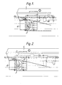
- a pipe system 2 is arranged in the stern part of the ship 1 hull so as to pass air to the front and to the rear of the propeller 3.
- the pipe system is provided with valves 4 for controlling the air quantity.
- the pipes that pass air to ahead of the propeller are opened in the rear face of the sternpost 5 of the ship and in the top face of the sole piece 15 as well as in the propeller.
- the pipes passing air to the rear side of the propeller are opened at the front edge of the rudder 6.
- the pipe system is provided with a fan 7 or with a compressor.
- the system may also be provided with a compressed-air tank 16.
- the propeller is located completely below the water level WL. When the ship runs forwards and the resistance to rotation of the propeller must be lowered because of ice, air is passed to ahead of the propeller, to its suction side.
- Fig. 2 illustrates an embodiment in which the air is received from the supercharger of the engine 17. This is advantageous in view of the operation of the engine.
- the supercharger viz., attempts to give the engine more supercharging air, which cannot be used by the engine as the speed of rotation is going down.
- FIGS 3 and 4 show a solution for the passage of air.
- the air pipe passes through the propeller 3 shaft 8 into the propeller hub 9, from which bores 10 pass into each blade. From each bore, openings 11 are opened into the face of the blade.
- Figures 5 and 6 show an application of the invention in connection with a nozzle propeller.
- the propeller 3 is surrounded by a nozzle 12 fixed to the hull 1 of the ship. Air is passed into the nozzle, and openings 13 are opened from it to ahead of the propeller, and openings 14 to the rear of the propeller.
- Fig. 7 shows an application of the invention to a ship provided with a tunnel stern, which is suitable for sailing in shallow waters.
- the bottom of the ship is curved upwards above the propeller so that a closed space 15 is formed facing the propeller above the waterline WL surrounding the ship, the propeller 3 extending partly into the said closed space.
- the propeller blades When air is passed into this space through a pipe system 2, the propeller blades also carry air along with them to underneath the water level. The air can be taken straight from the outdoor air, for the negative pressure prevailing in the closed space sucks air into the space through the pipe system 2 without an external pressure source when the valves 4 are open.
- the invention is not confined to the above embodiments only, but it n,ay show variation in many ways within the scope of the' patent claims.
- some other gas e.g. exhaust gas from the drive engine of the ship.
- the gas can also be pared to the propeller through particular projections fixed to the hull of the ship, which projections may, at the same time, guide ice off the propeller or water to the propeller. If the ship is provided with a steering propeller mounted on a turnable support, gas supply points may be placed on this support.
- the control of the gas supply may take place automatically or manually.
- the supply of gas may take place as such or as a mixture of gas and liquid.
- the gas or the mixture of gas and liquid may also contain particles of solid material. Bubbles of gas may also be formed by to the propeller or to its proximity feeding a chemical that produces formation of a gas in water, or by physical means, e.g. by decomposing water so that an electric current is passed into water.
Landscapes
- Chemical & Material Sciences (AREA)
- Engineering & Computer Science (AREA)
- Combustion & Propulsion (AREA)
- Mechanical Engineering (AREA)
- Ocean & Marine Engineering (AREA)
- Control Of Vehicle Engines Or Engines For Specific Uses (AREA)
- Structures Of Non-Positive Displacement Pumps (AREA)
- Other Liquid Machine Or Engine Such As Wave Power Use (AREA)
- Mixers Of The Rotary Stirring Type (AREA)
- Control Of Velocity Or Acceleration (AREA)
- Control Of Turbines (AREA)
- Toys (AREA)
Applications Claiming Priority (2)
| Application Number | Priority Date | Filing Date | Title |
|---|---|---|---|
| FI854197 | 1985-10-25 | ||
| FI854197A FI74920C (fi) | 1985-10-25 | 1985-10-25 | Foerfarande och system foer att minska rotationsmotstaondet i propeller. |
Publications (2)
| Publication Number | Publication Date |
|---|---|
| EP0221443A1 true EP0221443A1 (fr) | 1987-05-13 |
| EP0221443B1 EP0221443B1 (fr) | 1990-03-14 |
Family
ID=8521575
Family Applications (1)
| Application Number | Title | Priority Date | Filing Date |
|---|---|---|---|
| EP86114616A Expired - Lifetime EP0221443B1 (fr) | 1985-10-25 | 1986-10-22 | Méthode et aménagement pour réduire la résistance à la rotation d'une hélice de navire |
Country Status (10)
| Country | Link |
|---|---|
| US (2) | US4973275A (fr) |
| EP (1) | EP0221443B1 (fr) |
| JP (1) | JP2547321B2 (fr) |
| KR (1) | KR870003918A (fr) |
| CA (1) | CA1293158C (fr) |
| DE (1) | DE3669474D1 (fr) |
| DK (1) | DK161953C (fr) |
| FI (1) | FI74920C (fr) |
| NO (1) | NO864271L (fr) |
| SU (1) | SU1678199A3 (fr) |
Cited By (3)
| Publication number | Priority date | Publication date | Assignee | Title |
|---|---|---|---|---|
| GB2203989A (en) * | 1987-04-27 | 1988-11-02 | British Gas Plc | Method & device for effecting rotary action under water |
| WO2009041897A1 (fr) * | 2007-09-25 | 2009-04-02 | Stormfågeln Ab | Hélice de bateau possédant des pales d'hélice de surface |
| CN105501388A (zh) * | 2008-04-01 | 2016-04-20 | 国立研究开发法人海上技术安全研究所 | 船舶的摩擦阻力减小装置 |
Families Citing this family (19)
| Publication number | Priority date | Publication date | Assignee | Title |
|---|---|---|---|---|
| FI74920C (fi) * | 1985-10-25 | 1989-04-10 | Rauma Repola Oy | Foerfarande och system foer att minska rotationsmotstaondet i propeller. |
| FI82653C (fi) * | 1987-04-24 | 1991-04-10 | Antti Kalevi Henrik Jaervi | Foerfarande och anordningar foer avlaegsnande av is fraon raenna. |
| JPH0549598U (ja) * | 1991-12-17 | 1993-06-29 | 川崎重工業株式会社 | 舶用プロペラ翼の空気吹出し孔構造 |
| FI97351C (fi) * | 1993-11-22 | 1996-12-10 | Kvaerner Masa Yards Oy | Äänenvaimennusjärjestelmä |
| FI107040B (fi) * | 1997-07-31 | 2001-05-31 | Kvaerner Masa Yards Oy | Työlaivan käyttömenetelmä |
| DE10016990A1 (de) * | 2000-04-07 | 2001-10-25 | Arnold Schmalstieg | Motorbetriebenes Wasserfahrzeug |
| EP1334025B1 (fr) * | 2000-11-08 | 2005-08-10 | Fikret Dülger | Unite de poupe pour bateau |
| DE10135474B4 (de) * | 2001-07-20 | 2005-10-20 | Kvaerner Warnow Werft Gmbh | Schiff |
| NO20045623D0 (no) * | 2004-12-23 | 2004-12-23 | Goldfish Technology As | Hydrodynamisk kavitasjons kopling |
| RU2342550C1 (ru) * | 2007-04-05 | 2008-12-27 | Андрей Николаевич Муромцев | Способ повышения ресурса двигателя и снижения расхода топлива на теплоходах, имеющих двигатели с газотурбинным наддувом |
| JP5101210B2 (ja) * | 2007-08-16 | 2012-12-19 | 三菱重工業株式会社 | 船舶の推進装置 |
| US8800459B2 (en) * | 2011-08-12 | 2014-08-12 | Zuei-Ling Lin | Rudder resistance reducing method |
| US20130040513A1 (en) * | 2011-08-12 | 2013-02-14 | Zuei-Ling Lin | Hydraulic propeller enhancement method |
| KR101707498B1 (ko) * | 2012-11-05 | 2017-02-16 | 대우조선해양 주식회사 | 능동형 소음 제거 장치를 구비한 동적 위치 유지 시스템 |
| KR101475018B1 (ko) * | 2013-04-02 | 2014-12-22 | 삼성중공업 주식회사 | 애지머스 스러스터를 구비하는 선박 |
| KR101475019B1 (ko) * | 2013-04-03 | 2014-12-22 | 삼성중공업 주식회사 | 애지머스 스러스터를 구비하는 선박 |
| KR102111521B1 (ko) * | 2013-09-12 | 2020-05-15 | 대우조선해양 주식회사 | 압축공기 분사 전류고정날개 및 그 압축공기 분사 전류고정날개를 이용한 프로펠러의 캐비테이션 손상방지 시스템 |
| JP6097705B2 (ja) * | 2014-01-10 | 2017-03-15 | 信吉 森元 | 主プロペラ及び追加プロペラを装備する船の運航方法 |
| KR101894418B1 (ko) * | 2017-02-03 | 2018-09-04 | 삼성중공업 주식회사 | 해빙 기능을 갖는 추진장치 |
Citations (3)
| Publication number | Priority date | Publication date | Assignee | Title |
|---|---|---|---|---|
| FR2071402A5 (fr) * | 1969-12-29 | 1971-09-17 | Pastre De Bousquet R De | |
| US3745964A (en) * | 1971-08-19 | 1973-07-17 | Outboard Marine Corp | Racing lower unit |
| DE3129232A1 (de) * | 1981-07-24 | 1983-02-10 | Herbert 6927 Bad Rappenau Wunschik | "propeller" |
Family Cites Families (16)
| Publication number | Priority date | Publication date | Assignee | Title |
|---|---|---|---|---|
| DE650590C (de) * | 1937-09-25 | Ludwig Kort Dipl Ing | Vorrichtung zum gleichmaessigeren Verteilen des Schubes auf den ganzen Propellerkreis | |
| US1007583A (en) * | 1910-08-12 | 1911-10-31 | Christian E Loetzer | Motor-boat. |
| US4188906A (en) * | 1959-08-25 | 1980-02-19 | Miller Marlin L | Supercavitating propeller with air ventilation |
| GB1261024A (en) * | 1968-04-08 | 1972-01-19 | Lips Nv | Method and means for minimizing the actuating forces of a controllable pitch propeller |
| SU461861A1 (ru) * | 1971-11-22 | 1975-02-28 | Центральный Научно-Исследовательский И Проектно-Конструкторский Институт Механизации И Энергетики Лесной Промышленности | Движительно-рулевой комплекс судна |
| JPS49111392A (fr) * | 1973-02-25 | 1974-10-23 | ||
| US3924556A (en) * | 1973-04-09 | 1975-12-09 | Schottel Werft | Device for reducing the thrust of steerable propellers |
| SE377919B (fr) * | 1973-04-10 | 1975-08-04 | Karlstad Mekaniska Ab | |
| JPS5950557B2 (ja) * | 1977-04-26 | 1984-12-08 | 川崎重工業株式会社 | 危急停船を補助する方法 |
| JPS5587695A (en) * | 1978-12-21 | 1980-07-02 | Mitsubishi Heavy Ind Ltd | Air bubble injection blade |
| JPS5528639Y2 (fr) * | 1979-09-20 | 1980-07-08 | ||
| US4383829A (en) * | 1979-10-25 | 1983-05-17 | Great Lakes Power Products, Inc. | Drive assembly for inboard speedboat |
| JPS5942796U (ja) * | 1982-09-13 | 1984-03-21 | 三菱重工業株式会社 | 船舶用シヤフトブラケツト |
| JPS5957092A (ja) * | 1982-09-28 | 1984-04-02 | Mitsubishi Heavy Ind Ltd | プロペラ起振力軽減装置 |
| JPS6047792A (ja) * | 1983-08-26 | 1985-03-15 | Shigeo Shindo | 漁船用エンジンの過負荷防止方法 |
| FI74920C (fi) * | 1985-10-25 | 1989-04-10 | Rauma Repola Oy | Foerfarande och system foer att minska rotationsmotstaondet i propeller. |
-
1985
- 1985-10-25 FI FI854197A patent/FI74920C/fi not_active IP Right Cessation
-
1986
- 1986-10-17 DK DK497786A patent/DK161953C/da not_active IP Right Cessation
- 1986-10-17 CA CA000520768A patent/CA1293158C/fr not_active Expired - Lifetime
- 1986-10-22 DE DE8686114616T patent/DE3669474D1/de not_active Expired - Lifetime
- 1986-10-22 EP EP86114616A patent/EP0221443B1/fr not_active Expired - Lifetime
- 1986-10-23 KR KR1019860008894A patent/KR870003918A/ko not_active Withdrawn
- 1986-10-24 NO NO864271A patent/NO864271L/no unknown
- 1986-10-24 SU SU864028333A patent/SU1678199A3/ru active
- 1986-10-25 JP JP61254575A patent/JP2547321B2/ja not_active Expired - Lifetime
-
1989
- 1989-06-05 US US07/363,379 patent/US4973275A/en not_active Expired - Fee Related
-
1990
- 1990-08-28 US US07/573,730 patent/US5074813A/en not_active Expired - Fee Related
Patent Citations (3)
| Publication number | Priority date | Publication date | Assignee | Title |
|---|---|---|---|---|
| FR2071402A5 (fr) * | 1969-12-29 | 1971-09-17 | Pastre De Bousquet R De | |
| US3745964A (en) * | 1971-08-19 | 1973-07-17 | Outboard Marine Corp | Racing lower unit |
| DE3129232A1 (de) * | 1981-07-24 | 1983-02-10 | Herbert 6927 Bad Rappenau Wunschik | "propeller" |
Cited By (3)
| Publication number | Priority date | Publication date | Assignee | Title |
|---|---|---|---|---|
| GB2203989A (en) * | 1987-04-27 | 1988-11-02 | British Gas Plc | Method & device for effecting rotary action under water |
| WO2009041897A1 (fr) * | 2007-09-25 | 2009-04-02 | Stormfågeln Ab | Hélice de bateau possédant des pales d'hélice de surface |
| CN105501388A (zh) * | 2008-04-01 | 2016-04-20 | 国立研究开发法人海上技术安全研究所 | 船舶的摩擦阻力减小装置 |
Also Published As
| Publication number | Publication date |
|---|---|
| US4973275A (en) | 1990-11-27 |
| NO864271D0 (no) | 1986-10-24 |
| NO864271L (no) | 1987-04-27 |
| FI74920C (fi) | 1989-04-10 |
| DK497786D0 (da) | 1986-10-17 |
| FI74920B (fi) | 1987-12-31 |
| US5074813A (en) | 1991-12-24 |
| JPS62103296A (ja) | 1987-05-13 |
| DK161953B (da) | 1991-09-02 |
| DE3669474D1 (de) | 1990-04-19 |
| KR870003918A (ko) | 1987-05-06 |
| FI854197A0 (fi) | 1985-10-25 |
| CA1293158C (fr) | 1991-12-17 |
| JP2547321B2 (ja) | 1996-10-23 |
| EP0221443B1 (fr) | 1990-03-14 |
| SU1678199A3 (ru) | 1991-09-15 |
| FI854197L (fi) | 1987-04-26 |
| DK497786A (da) | 1987-04-26 |
| DK161953C (da) | 1992-02-03 |
Similar Documents
| Publication | Publication Date | Title |
|---|---|---|
| EP0221443A1 (fr) | Méthode et aménagement pour réduire la résistance à la rotation d'une hélice de navire | |
| EP0497776B1 (fr) | Navire monocoque rapide a poussee hydrodynamique ou monocoque semi-planant | |
| CN1128738C (zh) | 船舶推进器 | |
| US4832642A (en) | Outboard boat propulsion installation | |
| US20020162498A1 (en) | High speed M-shaped boat hull | |
| JP7334339B2 (ja) | 艦船の航行時の造波抵抗及び摩擦抵抗を低減する方法及び装置 | |
| CN2350310Y (zh) | 设有通水管道的增速船舶 | |
| US20110263168A1 (en) | Gaseous fluid vessel propulsion system | |
| US5231946A (en) | Monohull fast sealift or semi-planing monohull ship | |
| JP2020114732A (ja) | マリンダクトプロペラジェット推進システム | |
| US6250240B1 (en) | Water craft having ventilated propeller | |
| US5171175A (en) | Device with cavitational effect for propellers of watercraft with a planing or semiplaning keel | |
| US5145428A (en) | Shrouded propeller system for a sailboat | |
| US6629866B2 (en) | Marine vehicle propulsion system | |
| US5046975A (en) | Device with cavitational effect for propellers of watercraft with a planing or semiplaning keel | |
| US6024614A (en) | High performance marine propulsion system | |
| US3752110A (en) | Afterplane for marine jet-powered boats | |
| WO1992017366A1 (fr) | Bateau rapide monocoque | |
| US6855018B2 (en) | Propulsion system for boats | |
| GB2256410A (en) | A marine propulsion system. | |
| US20030070602A1 (en) | Ship supported by submerged structure | |
| KR20230147405A (ko) | 나선 스크류 추진 구조의 쌍동선 | |
| CN115402463A (zh) | 一种具备气体喷射装置的船舶减摩擦系统 | |
| WO1999029568A1 (fr) | Systeme de propulsion | |
| HK1055100A1 (en) | Semi-submergence type hydrofoil craft |
Legal Events
| Date | Code | Title | Description |
|---|---|---|---|
| PUAI | Public reference made under article 153(3) epc to a published international application that has entered the european phase |
Free format text: ORIGINAL CODE: 0009012 |
|
| AK | Designated contracting states |
Kind code of ref document: A1 Designated state(s): DE FR GB IT NL SE |
|
| 17P | Request for examination filed |
Effective date: 19870818 |
|
| 17Q | First examination report despatched |
Effective date: 19881012 |
|
| GRAA | (expected) grant |
Free format text: ORIGINAL CODE: 0009210 |
|
| RAP1 | Party data changed (applicant data changed or rights of an application transferred) |
Owner name: AQUAMASTER RAUMA OY |
|
| RBV | Designated contracting states (corrected) |
Designated state(s): DE SE |
|
| AK | Designated contracting states |
Kind code of ref document: B1 Designated state(s): DE SE |
|
| REF | Corresponds to: |
Ref document number: 3669474 Country of ref document: DE Date of ref document: 19900419 |
|
| PLBE | No opposition filed within time limit |
Free format text: ORIGINAL CODE: 0009261 |
|
| STAA | Information on the status of an ep patent application or granted ep patent |
Free format text: STATUS: NO OPPOSITION FILED WITHIN TIME LIMIT |
|
| 26N | No opposition filed | ||
| EAL | Se: european patent in force in sweden |
Ref document number: 86114616.5 |
|
| PGFP | Annual fee paid to national office [announced via postgrant information from national office to epo] |
Ref country code: SE Payment date: 19960930 Year of fee payment: 11 |
|
| PGFP | Annual fee paid to national office [announced via postgrant information from national office to epo] |
Ref country code: DE Payment date: 19961022 Year of fee payment: 11 |
|
| PG25 | Lapsed in a contracting state [announced via postgrant information from national office to epo] |
Ref country code: SE Free format text: LAPSE BECAUSE OF NON-PAYMENT OF DUE FEES Effective date: 19971023 |
|
| PG25 | Lapsed in a contracting state [announced via postgrant information from national office to epo] |
Ref country code: DE Free format text: LAPSE BECAUSE OF NON-PAYMENT OF DUE FEES Effective date: 19980701 |
|
| EUG | Se: european patent has lapsed |
Ref document number: 86114616.5 |