EP0223332A2 - Test instrument for optical fibres - Google Patents
Test instrument for optical fibres Download PDFInfo
- Publication number
- EP0223332A2 EP0223332A2 EP86305990A EP86305990A EP0223332A2 EP 0223332 A2 EP0223332 A2 EP 0223332A2 EP 86305990 A EP86305990 A EP 86305990A EP 86305990 A EP86305990 A EP 86305990A EP 0223332 A2 EP0223332 A2 EP 0223332A2
- Authority
- EP
- European Patent Office
- Prior art keywords
- fiber
- light
- test instrument
- further characterized
- jaw members
- Prior art date
- Legal status (The legal status is an assumption and is not a legal conclusion. Google has not performed a legal analysis and makes no representation as to the accuracy of the status listed.)
- Granted
Links
Images
Classifications
-
- G—PHYSICS
- G01—MEASURING; TESTING
- G01M—TESTING STATIC OR DYNAMIC BALANCE OF MACHINES OR STRUCTURES; TESTING OF STRUCTURES OR APPARATUS, NOT OTHERWISE PROVIDED FOR
- G01M11/00—Testing of optical apparatus; Testing structures by optical methods not otherwise provided for
- G01M11/30—Testing of optical devices, constituted by fibre optics or optical waveguides
- G01M11/35—Testing of optical devices, constituted by fibre optics or optical waveguides in which light is transversely coupled into or out of the fibre or waveguide, e.g. using integrating spheres
-
- G—PHYSICS
- G01—MEASURING; TESTING
- G01M—TESTING STATIC OR DYNAMIC BALANCE OF MACHINES OR STRUCTURES; TESTING OF STRUCTURES OR APPARATUS, NOT OTHERWISE PROVIDED FOR
- G01M11/00—Testing of optical apparatus; Testing structures by optical methods not otherwise provided for
- G01M11/08—Testing mechanical properties
- G01M11/088—Testing mechanical properties of optical fibres; Mechanical features associated with the optical testing of optical fibres
-
- G—PHYSICS
- G02—OPTICS
- G02B—OPTICAL ELEMENTS, SYSTEMS OR APPARATUS
- G02B6/00—Light guides; Structural details of arrangements comprising light guides and other optical elements, e.g. couplings
- G02B6/24—Coupling light guides
- G02B6/42—Coupling light guides with opto-electronic elements
- G02B6/4201—Packages, e.g. shape, construction, internal or external details
- G02B6/4286—Optical modules with optical power monitoring
-
- G—PHYSICS
- G02—OPTICS
- G02B—OPTICAL ELEMENTS, SYSTEMS OR APPARATUS
- G02B6/00—Light guides; Structural details of arrangements comprising light guides and other optical elements, e.g. couplings
- G02B6/24—Coupling light guides
- G02B6/42—Coupling light guides with opto-electronic elements
- G02B6/4201—Packages, e.g. shape, construction, internal or external details
- G02B6/4287—Optical modules with tapping or launching means through the surface of the waveguide
- G02B6/4289—Optical modules with tapping or launching means through the surface of the waveguide by inducing bending, microbending or macrobending, to the light guide
Definitions
- This invention relates to a portable self-contained test instrument for identifying whether an optical fiber is live, that is, whether light is propagating along the fiber.
- telecommunications workers working with fiber optic cables must distinguish between live (i.e. traffic carrying) and spare fibers.
- the act of identifying a live fiber must not be such as to overly attenuate or distort the propagating signal and nor must the intrusion be such as to operate any diagnostic alarms used to. monitor the fibre or cable integrity.
- Light is directed into one fiber upstream of the splice or connection site using the local launch device and is detected using the local detection device at a location immediately downstream of the site.
- the two fiber ends are moved relative to one another until the light level measured at the local detection unit is maximized.
- the radius of curvature at the bend in the local launch and detection devices is made relatively small, of the order of 2.8 millimeters, and the light source and photodetectors in the respective launch and detection devices are constrained to critical positions in relation to the fiber bend since the input and output light respectively is confined to a narrow beam.
- KAWASAKI et al entitled FIBER OPTIC COUPLER does not lend itself to incorporation within a portable and easily usable test instrument for detecting merely the presence or absence of light within an optical fiber. Also, the induced loss in the fiber due to use of the above device is well above the threshold for triggering diagnostic alarms.
- a further patent concerned with the emission of light from a bend within an optical fiber is U.S. Patent 4,270,839 (Cross).
- the intention of the assembly described in this patent is as an optical fiber signal tap.
- the arrangement depends on positioning the fiber accurately in a pair of light pipes which can be incrementally moved to displace their axes. Initially the fiber extends along the axes of the two light pipes which are positioned contiguously but with ends spaced from one another. Then as one light pipe is moved so that its axis is displaced from the axis of the other light pipe, light is scattered from the small intervening section of fiber and enters the downstream light pipe. Again this arrangement is not adapted to permit rapid testing of live fibers.
- a method for detecting whether light is propagating in an optical fiber comprising: introducing a bend into the fiber to cause any light propagating therein to be scattered from the fiber; detecting said scattered light;
- a test instrument for detecting whether light is propagating in an optical fiber comprising:
- the bending means includes first and second jaw members, one of the jaw members having a convex body part with "vee” groove to guide the fiber along the center of convex body part, thereby insuring the fiber is positioned for optimum light detection.
- an optical fiber placed between the jaw members is constrained to adopt the curvature of said convex body part.
- Said convex body part can be a rod shaped part with a vee groove around its circumference.
- the other jaw member can be lined with resilient, closed cell foam so as to press the fiber into conformation with the convex part of the first jaw member, without inducing any excess loss in the fiber.
- the first jaw member can be spring mounted relative to the second jaw member, the first jaw member being moved against a spring bias to permit a fiber to be positioned within the jaw.
- the first jaw member when released, is spring biased towards the second jaw member to constrain said fiber.
- the detection means can include a lens to focus light scattered from the bend in the fibre at an avalanche or PIN photodiode.
- the cooperating jaw members are symmetrical about an optical axis extending through the lens and through the center of the photodiode. This arrangement results in the device being bidirectional (i.e. detects light propagating in both directions).
- An alternative arrangement with the detector positioned 90° off axis allows the operator to determine the direction (R to L or L to R) of light propagation.
- the generating means can include a switch for directing current from batteries mounted within the test instrument to an LED to the indicator circuit. Suitable transducers are light emitting diodes - (LEDs) and a tone generator. The switch may be of the momentary contact type. Pressing the switch button illuminates either a green LED, indicating light propagation, or a red LED indicating no light and sufficient battery power.
- the test instrument preferably has a barrel portion and a cap portion, the first jaw member being present within the cap portion and the second jaw member, the detection means, the generating means and the indicator circuit being mounted within the barrel portion.
- the barrel portion can have a compartment for the power source, a separate compartment for electronic components forming the generating means and the indicator circuit, and a third compartment being encompassed by said cap portion and containing the detection means and said second jaw member.
- the test instrument 10 has a barrel 12 and a cap 14.
- the cap 14 has an aperture 16 extending partially around its perimeter and spaced from the end of the cap.
- the cap end is formed with a rib 18 facing towards the barrel 12.
- Fixed within a recess at the end of the rib is a cylinder 42 with a vee groove 48 about its circumference.
- the barrel has relatively thick wall portions 20 which have convex outer edges, the inside of these wall portions being lined with a resilient closed cell foam 41.
- the cap is spring mounted by means of a spring 43 cooperating with abutments to bias the cap towards the barrel.
- the spring mounting permits movement of the cap 14 away from the barrel 12 to allow insertion of a fiber 22 between the cylinder 42 and the foam 41 so that the cylinder and the foam portions 41 meet and function as a pair of cooperating jaws to clamp the fiber 22.
- Spaced from the cylinder 42 is a lens 24 positioned to focus any light scattered from a curved section of the fiber at a photodetector 26.
- the left-hand compartment 28 serving to house a battery power source 30 and the right-hand compartment 32 housing electronic circuitry 34 including a threshold detector for assessing whether light detected by photodetector 26 is above a predetermined threshold level, and an indicator circuit which is energized if the detected light exceeds that threshold.
- the cap 14 is moved against the spring bias to open up the aperture 16 between the cylinder 42 and the facing wall parts 20 and the fiber 22 is threaded through the instrument.
- the cap 18 is then carefully released and the spring bias moves the cap so that the cylinder 42 presses the fiber 22 against the foam 41 lining wall portions 20 so that the fiber adopts the curvature of the cylinder 42.
- Closed cell foam 47 on the cap part serves both to clamp the fiber and to shield it and the detector 26 from ambient light. If the fiber 22 is transmitting light, a certain amount of light is scattered and is focussed by the converging lens 24 onto the detector 26.
- the indicator circuit of Figure 4 is energized and a green LED 45 is illuminated. If the fiber is not carrying light, the energized circuit caused a red LED 46 to illuminate, indicating sufficient battery power but no light scattered from the fiber.
- the instrument is held in one hand with the barrel part 28 in the palm of the hand and the cap is moved against spring bias by thumb pressure on a projection 36.
- the fiber 22 is let into the aperture 16 using the other hand.
- the batteries 30 are replaced when necessary in a normal flashlight manner by unscrewing a cap 38 at the remote end of the barrel and sliding the batteries from the barrel 12.
- the curvature of the fiber extending around the rib 18 is important. If the radius of curvature of the rib is too small, then untenable loss may result in the transmitted signal resulting in system alarms. On the other hand, if the radius of curvature is too large, then little light will be scattered from the fiber and it is impossible to judge whether the fiber is live.
- rod radius of curvature is approximately 8 millimeters.
- FIG. 5 an alternative arrangement of the cap end is shown in which lens 24 and photodiode 26 are mounted asymmetrically of the curved fiber.
- Figure 5 shows part of an instrument which can be used only for detecting light propagating unidirectionally along the fiber in the direction of arrow A.
- the arrangement of the jaw members is different from that shown in Figures 1 to 5.
- the rod 42 with fiber seating "vee" groove 48 is mounted on a first jaw member 50 corresponding to the cap 14 and the other jaw member 52 is mounted on the barrel portion 12 in an orientation different from that shown in Figure 1.
- the jaw members 50, 52 are hinged at an axis at which a torsion spring 54 is located to urge the jaw members 50, 52 together.
- the jaw member are forced apart about the axis to let in the test fiber 22 and then are released to allow the test to be made.
- the arrangement resembles that of Figure 1.
Landscapes
- Physics & Mathematics (AREA)
- General Physics & Mathematics (AREA)
- Optics & Photonics (AREA)
- Chemical & Material Sciences (AREA)
- Analytical Chemistry (AREA)
- Photometry And Measurement Of Optical Pulse Characteristics (AREA)
- Light Guides In General And Applications Therefor (AREA)
- Testing Of Optical Devices Or Fibers (AREA)
- Investigating Or Analysing Materials By Optical Means (AREA)
Abstract
Description
- This invention relates to a portable self-contained test instrument for identifying whether an optical fiber is live, that is, whether light is propagating along the fiber.
- For repair and branching purposes, telecommunications workers working with fiber optic cables must distinguish between live (i.e. traffic carrying) and spare fibers. The act of identifying a live fiber must not be such as to overly attenuate or distort the propagating signal and nor must the intrusion be such as to operate any diagnostic alarms used to. monitor the fibre or cable integrity.
- Our co-pending patent application in the name of Brian S. KAWASAKI et al, Canadian Serial Number 453,707, filed 7 May 1984 entitled FIBER OPTIC COUPLER, describes a device for measuring the light propagating in a fiber by introducing a bend into the fiber and detecting the light emitted at the bend with a photodetector. The photodetector is connected into a level detection circuit which includes a visual read-out means from which the level of light emitted at the bend can be read. The detection device is used in association with a light launching device when effecting a splice or connection between contiguous fibers. Light is directed into one fiber upstream of the splice or connection site using the local launch device and is detected using the local detection device at a location immediately downstream of the site. The two fiber ends are moved relative to one another until the light level measured at the local detection unit is maximized. In order to maximize light input and output at the local launch and detection devices respectively, the radius of curvature at the bend in the local launch and detection devices is made relatively small, of the order of 2.8 millimeters, and the light source and photodetectors in the respective launch and detection devices are constrained to critical positions in relation to the fiber bend since the input and output light respectively is confined to a narrow beam. The arrangement of elements within the local detection unit described in the above-mentioned co-pending patent application in the name of Brian S. KAWASAKI et al, entitled FIBER OPTIC COUPLER does not lend itself to incorporation within a portable and easily usable test instrument for detecting merely the presence or absence of light within an optical fiber. Also, the induced loss in the fiber due to use of the above device is well above the threshold for triggering diagnostic alarms.
- A further patent concerned with the emission of light from a bend within an optical fiber is U.S. Patent 4,270,839 (Cross). The intention of the assembly described in this patent is as an optical fiber signal tap. The arrangement depends on positioning the fiber accurately in a pair of light pipes which can be incrementally moved to displace their axes. Initially the fiber extends along the axes of the two light pipes which are positioned contiguously but with ends spaced from one another. Then as one light pipe is moved so that its axis is displaced from the axis of the other light pipe, light is scattered from the small intervening section of fiber and enters the downstream light pipe. Again this arrangement is not adapted to permit rapid testing of live fibers.
- According to one aspect of the invention there is provided a method for detecting whether light is propagating in an optical fiber comprising: introducing a bend into the fiber to cause any light propagating therein to be scattered from the fiber; detecting said scattered light;
- generating a corresponding electrical output if said detected light is greater than a predetermined threshold level; and
- directing said electrical output to an indicator circuit to operate a transducer whereby to indicate to an operator the presence of light in the fiber.
- According to another aspect of the invention, there is. provided a test instrument for detecting whether light is propagating in an optical fiber comprising:
- bending means for introducing a bend into the fiber to cause any light propagating therein to be scattered therefrom;
- detection means for detecting scattered light;
- generating means for generating a corresponding electrical output if said detected light is greater than a predetermined threshold level; and an indicator circuit including a transducer energizable by an output from said generating means whereby to indicate to an operator the presence of light in the fiber.
- Preferably the bending means includes first and second jaw members, one of the jaw members having a convex body part with "vee" groove to guide the fiber along the center of convex body part, thereby insuring the fiber is positioned for optimum light detection. When said one jaw member moves towards the other jaw member, an optical fiber placed between the jaw members is constrained to adopt the curvature of said convex body part. Said convex body part can be a rod shaped part with a vee groove around its circumference. The other jaw member can be lined with resilient, closed cell foam so as to press the fiber into conformation with the convex part of the first jaw member, without inducing any excess loss in the fiber.
- The first jaw member can be spring mounted relative to the second jaw member, the first jaw member being moved against a spring bias to permit a fiber to be positioned within the jaw. The first jaw member, when released, is spring biased towards the second jaw member to constrain said fiber.
- The detection means can include a lens to focus light scattered from the bend in the fibre at an avalanche or PIN photodiode. Preferably the cooperating jaw members are symmetrical about an optical axis extending through the lens and through the center of the photodiode. This arrangement results in the device being bidirectional (i.e. detects light propagating in both directions). An alternative arrangement with the detector positioned 90° off axis allows the operator to determine the direction (R to L or L to R) of light propagation. The generating means can include a switch for directing current from batteries mounted within the test instrument to an LED to the indicator circuit. Suitable transducers are light emitting diodes - (LEDs) and a tone generator. The switch may be of the momentary contact type. Pressing the switch button illuminates either a green LED, indicating light propagation, or a red LED indicating no light and sufficient battery power.
- The test instrument preferably has a barrel portion and a cap portion, the first jaw member being present within the cap portion and the second jaw member, the detection means, the generating means and the indicator circuit being mounted within the barrel portion. The barrel portion can have a compartment for the power source, a separate compartment for electronic components forming the generating means and the indicator circuit, and a third compartment being encompassed by said cap portion and containing the detection means and said second jaw member.
- An embodiment of the invention will now be described by way of example with reference to the accompanying drawings in which:-
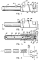
- Figure 1 is a side elevation of a test instrument according to the invention, the instrument being shown with jaws open;
- Figure 2 is a side elevation of the instrument with the jaws closed;
- Figure 3 is a longitudinal sectional view on line III-III of Figure 2;
- Figure 4 shows a light detection and indicator circuit used in the test instrument of Figure 1;
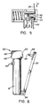
- Figure 5 shows a detail of the Figure 3 sectional view showing the jaw members and monitoring optics in an alternative disposition; and
- Figure 6 is a side elevation of an alternative test instrument in which cooperating jaw members are mounted together using a torsion spring.
- Referring to the Figures in detail, the
test instrument 10 has abarrel 12 and a cap 14. The cap 14 has an aperture 16 extending partially around its perimeter and spaced from the end of the cap. The cap end is formed with arib 18 facing towards thebarrel 12. Fixed within a recess at the end of the rib is acylinder 42 with avee groove 48 about its circumference. At the cap end, the barrel has relativelythick wall portions 20 which have convex outer edges, the inside of these wall portions being lined with a resilient closedcell foam 41. The cap is spring mounted by means of aspring 43 cooperating with abutments to bias the cap towards the barrel. The spring mounting permits movement of the cap 14 away from thebarrel 12 to allow insertion of afiber 22 between thecylinder 42 and thefoam 41 so that the cylinder and thefoam portions 41 meet and function as a pair of cooperating jaws to clamp thefiber 22. Spaced from thecylinder 42 is alens 24 positioned to focus any light scattered from a curved section of the fiber at aphotodetector 26. - Within the
barrel 12 are two compartments, the left-hand compartment 28 serving to house abattery power source 30 and the right-hand compartment 32 housingelectronic circuitry 34 including a threshold detector for assessing whether light detected byphotodetector 26 is above a predetermined threshold level, and an indicator circuit which is energized if the detected light exceeds that threshold. - In use, the cap 14 is moved against the spring bias to open up the aperture 16 between the
cylinder 42 and the facingwall parts 20 and thefiber 22 is threaded through the instrument. Thecap 18 is then carefully released and the spring bias moves the cap so that thecylinder 42 presses thefiber 22 against thefoam 41lining wall portions 20 so that the fiber adopts the curvature of thecylinder 42. Closedcell foam 47 on the cap part serves both to clamp the fiber and to shield it and thedetector 26 from ambient light. If thefiber 22 is transmitting light, a certain amount of light is scattered and is focussed by the converginglens 24 onto thedetector 26. When holding aswitch button 44, and if the detected light is above the threshold level, the indicator circuit of Figure 4 is energized and agreen LED 45 is illuminated. If the fiber is not carrying light, the energized circuit caused ared LED 46 to illuminate, indicating sufficient battery power but no light scattered from the fiber. - The instrument is held in one hand with the
barrel part 28 in the palm of the hand and the cap is moved against spring bias by thumb pressure on aprojection 36. Thefiber 22 is let into the aperture 16 using the other hand. Thebatteries 30 are replaced when necessary in a normal flashlight manner by unscrewing acap 38 at the remote end of the barrel and sliding the batteries from thebarrel 12. - The curvature of the fiber extending around the
rib 18 is important. If the radius of curvature of the rib is too small, then untenable loss may result in the transmitted signal resulting in system alarms. On the other hand, if the radius of curvature is too large, then little light will be scattered from the fiber and it is impossible to judge whether the fiber is live. For conventional monomode fibers having a doped silica core and pure silica cladding together with an acrylate coating is suitable rod radius of curvature is approximately 8 millimeters. - Referring to Figure 5 an alternative arrangement of the cap end is shown in which
lens 24 andphotodiode 26 are mounted asymmetrically of the curved fiber. Unlike the previous embodiment Figure 5 shows part of an instrument which can be used only for detecting light propagating unidirectionally along the fiber in the direction of arrow A. Referring to Figure 6, the arrangement of the jaw members is different from that shown in Figures 1 to 5. Here therod 42 with fiber seating "vee"groove 48 is mounted on afirst jaw member 50 corresponding to the cap 14 and theother jaw member 52 is mounted on thebarrel portion 12 in an orientation different from that shown in Figure 1. Thejaw members torsion spring 54 is located to urge thejaw members test fiber 22 and then are released to allow the test to be made. In other respects, the arrangement resembles that of Figure 1.
Claims (15)
Applications Claiming Priority (3)
| Application Number | Priority Date | Filing Date | Title |
|---|---|---|---|
| CA491314 | 1985-09-23 | ||
| CA000491314A CA1234897A (en) | 1985-09-23 | 1985-09-23 | Test instrument |
| US06/780,149 US4671653A (en) | 1985-09-23 | 1985-09-26 | Test instrument for an optical fiber |
Publications (3)
| Publication Number | Publication Date |
|---|---|
| EP0223332A2 true EP0223332A2 (en) | 1987-05-27 |
| EP0223332A3 EP0223332A3 (en) | 1988-06-29 |
| EP0223332B1 EP0223332B1 (en) | 1991-03-06 |
Family
ID=25670791
Family Applications (1)
| Application Number | Title | Priority Date | Filing Date |
|---|---|---|---|
| EP86305990A Expired - Lifetime EP0223332B1 (en) | 1985-09-23 | 1986-08-04 | Test instrument for optical fibres |
Country Status (5)
| Country | Link |
|---|---|
| US (1) | US4671653A (en) |
| EP (1) | EP0223332B1 (en) |
| JP (1) | JPS6273136A (en) |
| AU (1) | AU587048B2 (en) |
| CA (1) | CA1234897A (en) |
Cited By (6)
| Publication number | Priority date | Publication date | Assignee | Title |
|---|---|---|---|---|
| EP0436354A1 (en) * | 1989-12-21 | 1991-07-10 | BICC Public Limited Company | Handtool for optical fibre signal determination by bending |
| EP0478296A3 (en) * | 1990-09-28 | 1993-02-24 | Minnesota Mining And Manufacturing Company | Fiber identifier |
| EP0485849A3 (en) * | 1990-11-13 | 1993-03-03 | Siemens Aktiengesellschaft | Measuring device for an optical medium using two emitters and two receivers |
| WO1997003344A1 (en) * | 1995-07-10 | 1997-01-30 | Minnesota Mining And Manufacturing Company | Multiple-size optical fiber identifier |
| RU2147133C1 (en) * | 1998-12-30 | 2000-03-27 | Поволжская государственная академия телекоммуникаций и информатики | Method determining distance to point of fault in sheath of optical fiber and device for its implementation |
| WO2009019389A3 (en) * | 2007-07-23 | 2009-04-23 | France Telecom | Signal detection in optical fibre |
Families Citing this family (24)
| Publication number | Priority date | Publication date | Assignee | Title |
|---|---|---|---|---|
| US4797556A (en) * | 1986-03-21 | 1989-01-10 | Amp Incorporated | Optical continuity testing apparatus with pulsating transmitter |
| US4800265A (en) * | 1986-03-21 | 1989-01-24 | Amp Incorporated | Optical fiber continuity testing with pulsating optical test signal |
| USD303359S (en) | 1986-09-02 | 1989-09-12 | Amp Incorporated | Optical continuity testing transmitter |
| US4833088A (en) * | 1987-09-25 | 1989-05-23 | Miles Inc. | Reagent strip handling mechanism |
| GB8800667D0 (en) * | 1988-01-13 | 1988-02-10 | British Telecomm | Optical power meter |
| US4812743A (en) * | 1988-01-13 | 1989-03-14 | Northern Telecom Limited | Method and apparatus for detecting a narrowband signal |
| GB8800666D0 (en) * | 1988-01-13 | 1988-02-10 | British Telecomm | Optical fibre handling apparatus |
| CA1306527C (en) * | 1988-09-30 | 1992-08-18 | John Didwith Lewis | Optical fibre monitoring |
| GB8828505D0 (en) * | 1988-12-07 | 1989-01-11 | Bicc Plc | Optical fibre monitoring |
| CA1312757C (en) * | 1989-09-27 | 1993-01-19 | Shawn Joseph Morrison | Optical fiber coupling device and method for its use |
| US5159399A (en) * | 1990-10-04 | 1992-10-27 | Siemens Aktiengesellschaft | Measuring device for an optical medium having a light receiver guidable to either of two measuring locations |
| AU648431B2 (en) * | 1991-06-25 | 1994-04-21 | British Telecommunications Public Limited Company | Light transfer means |
| US5191207A (en) * | 1991-08-28 | 1993-03-02 | Leon Guerrero Harry C | Optical detector apparatus with rigid positioning fixture |
| ATE143504T1 (en) * | 1992-03-04 | 1996-10-15 | Siemens Ag | FIBER FIBER SIGNAL DETECTOR |
| US5742715A (en) * | 1995-12-21 | 1998-04-21 | Lucent Technologies Inc. | Optical fiber status analyzer and related methods |
| US5781285A (en) * | 1996-12-23 | 1998-07-14 | Nuvisions International, Inc. | Method and apparatus for monitoring presence and direction of light in optical fibers |
| US6094261A (en) * | 1998-01-29 | 2000-07-25 | L-Com, Inc. | Method and apparatus for distinguishing fiber-optic cables |
| US8729459B2 (en) * | 2010-03-25 | 2014-05-20 | Conolog Corporation | Apparatus and method for detecting optical energy in an optical fiber |
| TWI911693B (en) | 2018-02-27 | 2026-01-11 | 美商Ctc全球公司 | Systems, methods and tools for the interrogation of composite strength members |
| CN108593267A (en) * | 2018-04-13 | 2018-09-28 | 苏州拓博机械设备有限公司 | A kind of optical fiber combined type testing machine |
| CN112230347B (en) * | 2020-10-23 | 2022-04-19 | 青岛海信宽带多媒体技术有限公司 | Optical module |
| CN113607192B (en) * | 2021-09-30 | 2021-12-14 | 武汉长盈通光电技术股份有限公司 | Indirect connection type optical fiber gyro assembly testing device |
| US12212362B2 (en) | 2021-12-07 | 2025-01-28 | Panduit Corp. | Apparatus and methods for monitoring optical networks |
| CN114384068B (en) * | 2021-12-27 | 2023-09-08 | 中国科学院福建物质结构研究所 | Measuring device, measuring method and application for measuring weak anisotropy in large-size isotropic laser medium |
Family Cites Families (7)
| Publication number | Priority date | Publication date | Assignee | Title |
|---|---|---|---|---|
| DE2717412C3 (en) * | 1977-04-20 | 1980-08-21 | Felten & Guilleaume Carlswerk Ag, 5000 Koeln | Continuity tester for optical fibers |
| JPS549647A (en) * | 1977-06-23 | 1979-01-24 | Nippon Telegr & Teleph Corp <Ntt> | Loss measuring method of optical fibers |
| JPS5949561B2 (en) * | 1980-07-24 | 1984-12-04 | 日本電信電話株式会社 | Optical fiber core detector |
| DE3039088A1 (en) * | 1980-10-16 | 1981-10-29 | Deutsche Bundespost vertreten durch den Präsidenten des Fernmeldetechnischen Zentralamtes, 6100 Darmstadt | Examining right wave conducting cable transfer characteristics - using sinusoidally moving carriage with cable rollers during mechanical stress |
| JPS5958404A (en) * | 1982-09-29 | 1984-04-04 | Nippon Telegr & Teleph Corp <Ntt> | Method and device for nonbreak detection of optical fiber propagating light |
| GB8419408D0 (en) * | 1984-07-30 | 1984-09-05 | Bicc Plc | Optical fibre splicing |
| GB8420135D0 (en) * | 1984-08-08 | 1984-09-12 | Bicc Plc | Optical fibre splicing |
-
1985
- 1985-09-23 CA CA000491314A patent/CA1234897A/en not_active Expired
- 1985-09-26 US US06/780,149 patent/US4671653A/en not_active Expired - Lifetime
-
1986
- 1986-07-18 AU AU60333/86A patent/AU587048B2/en not_active Ceased
- 1986-08-04 EP EP86305990A patent/EP0223332B1/en not_active Expired - Lifetime
- 1986-09-22 JP JP61222227A patent/JPS6273136A/en active Pending
Cited By (6)
| Publication number | Priority date | Publication date | Assignee | Title |
|---|---|---|---|---|
| EP0436354A1 (en) * | 1989-12-21 | 1991-07-10 | BICC Public Limited Company | Handtool for optical fibre signal determination by bending |
| EP0478296A3 (en) * | 1990-09-28 | 1993-02-24 | Minnesota Mining And Manufacturing Company | Fiber identifier |
| EP0485849A3 (en) * | 1990-11-13 | 1993-03-03 | Siemens Aktiengesellschaft | Measuring device for an optical medium using two emitters and two receivers |
| WO1997003344A1 (en) * | 1995-07-10 | 1997-01-30 | Minnesota Mining And Manufacturing Company | Multiple-size optical fiber identifier |
| RU2147133C1 (en) * | 1998-12-30 | 2000-03-27 | Поволжская государственная академия телекоммуникаций и информатики | Method determining distance to point of fault in sheath of optical fiber and device for its implementation |
| WO2009019389A3 (en) * | 2007-07-23 | 2009-04-23 | France Telecom | Signal detection in optical fibre |
Also Published As
| Publication number | Publication date |
|---|---|
| CA1234897A (en) | 1988-04-05 |
| AU6033386A (en) | 1987-03-26 |
| US4671653A (en) | 1987-06-09 |
| EP0223332B1 (en) | 1991-03-06 |
| AU587048B2 (en) | 1989-08-03 |
| JPS6273136A (en) | 1987-04-03 |
| EP0223332A3 (en) | 1988-06-29 |
Similar Documents
| Publication | Publication Date | Title |
|---|---|---|
| EP0223332B1 (en) | Test instrument for optical fibres | |
| EP0230938B1 (en) | Optical fiber signal test device | |
| JP5052530B2 (en) | Installation tool with integrated visual point of failure measuring instrument for field-installable mechanical splice connectors | |
| JP5199883B2 (en) | Apparatus and method for verifying acceptable splice termination connections | |
| US4561719A (en) | Optical waveguide splicing apparatus and method | |
| US5315365A (en) | Macrobend splice loss tester for fiber optic splices with silicon gel cushion on optical coupling blocks | |
| FR2422971A1 (en) | FIXED OPTICAL ATTENUATOR FOR LUMINOUS RADIATION GUIDED BY OPTICAL FIBER | |
| EP0785439A3 (en) | Device for optically measuring physical quantity in power equipment and method of manufacturing the same | |
| US4372768A (en) | Method of splicing ends of optical fibers | |
| CA1332291C (en) | Optical power meter | |
| EP0591340B1 (en) | Light transfer method | |
| JPS63131106A (en) | Connection loss testing instrument for optical fiber connection part | |
| ATE161950T1 (en) | METHOD AND DEVICE FOR MEASURING SEVERAL OPTICAL FIBERS | |
| AU609253B2 (en) | Optical power meter | |
| KR870003399A (en) | Inspection device | |
| GB2273407B (en) | Monitoring of optical communications fibres | |
| HK1010798B (en) | Light transfer method | |
| JPS5930037A (en) | Optical tester |
Legal Events
| Date | Code | Title | Description |
|---|---|---|---|
| PUAI | Public reference made under article 153(3) epc to a published international application that has entered the european phase |
Free format text: ORIGINAL CODE: 0009012 |
|
| AK | Designated contracting states |
Kind code of ref document: A2 Designated state(s): DE FR GB NL |
|
| PUAL | Search report despatched |
Free format text: ORIGINAL CODE: 0009013 |
|
| AK | Designated contracting states |
Kind code of ref document: A3 Designated state(s): DE FR GB NL |
|
| 17P | Request for examination filed |
Effective date: 19890118 |
|
| 17Q | First examination report despatched |
Effective date: 19900618 |
|
| GRAA | (expected) grant |
Free format text: ORIGINAL CODE: 0009210 |
|
| AK | Designated contracting states |
Kind code of ref document: B1 Designated state(s): DE FR GB NL |
|
| REF | Corresponds to: |
Ref document number: 3677898 Country of ref document: DE Date of ref document: 19910411 |
|
| ET | Fr: translation filed | ||
| PLBE | No opposition filed within time limit |
Free format text: ORIGINAL CODE: 0009261 |
|
| STAA | Information on the status of an ep patent application or granted ep patent |
Free format text: STATUS: NO OPPOSITION FILED WITHIN TIME LIMIT |
|
| 26N | No opposition filed | ||
| REG | Reference to a national code |
Ref country code: GB Ref legal event code: IF02 |
|
| PGFP | Annual fee paid to national office [announced via postgrant information from national office to epo] |
Ref country code: NL Payment date: 20020722 Year of fee payment: 17 |
|
| PGFP | Annual fee paid to national office [announced via postgrant information from national office to epo] |
Ref country code: GB Payment date: 20020731 Year of fee payment: 17 |
|
| PG25 | Lapsed in a contracting state [announced via postgrant information from national office to epo] |
Ref country code: GB Free format text: LAPSE BECAUSE OF NON-PAYMENT OF DUE FEES Effective date: 20030804 |
|
| PGFP | Annual fee paid to national office [announced via postgrant information from national office to epo] |
Ref country code: FR Payment date: 20030820 Year of fee payment: 18 |
|
| PG25 | Lapsed in a contracting state [announced via postgrant information from national office to epo] |
Ref country code: NL Free format text: LAPSE BECAUSE OF NON-PAYMENT OF DUE FEES Effective date: 20040301 |
|
| GBPC | Gb: european patent ceased through non-payment of renewal fee |
Effective date: 20030804 |
|
| NLV4 | Nl: lapsed or anulled due to non-payment of the annual fee |
Effective date: 20040301 |
|
| PGFP | Annual fee paid to national office [announced via postgrant information from national office to epo] |
Ref country code: DE Payment date: 20040930 Year of fee payment: 19 |
|
| PG25 | Lapsed in a contracting state [announced via postgrant information from national office to epo] |
Ref country code: FR Free format text: LAPSE BECAUSE OF NON-PAYMENT OF DUE FEES Effective date: 20050429 |
|
| REG | Reference to a national code |
Ref country code: FR Ref legal event code: ST |
|
| PG25 | Lapsed in a contracting state [announced via postgrant information from national office to epo] |
Ref country code: DE Free format text: LAPSE BECAUSE OF NON-PAYMENT OF DUE FEES Effective date: 20060301 |