EP0223532B1 - Verfahren zur Optimierung von Strömungsbildern und zum Vergrössern von Signal/Geräusch-Verhältnissen in elektrochemischen Durchflusssensoren - Google Patents
Verfahren zur Optimierung von Strömungsbildern und zum Vergrössern von Signal/Geräusch-Verhältnissen in elektrochemischen Durchflusssensoren Download PDFInfo
- Publication number
- EP0223532B1 EP0223532B1 EP86308743A EP86308743A EP0223532B1 EP 0223532 B1 EP0223532 B1 EP 0223532B1 EP 86308743 A EP86308743 A EP 86308743A EP 86308743 A EP86308743 A EP 86308743A EP 0223532 B1 EP0223532 B1 EP 0223532B1
- Authority
- EP
- European Patent Office
- Prior art keywords
- fluid
- cell
- settable
- immiscible
- polymer
- Prior art date
- Legal status (The legal status is an assumption and is not a legal conclusion. Google has not performed a legal analysis and makes no representation as to the accuracy of the status listed.)
- Expired
Links
- 238000000034 method Methods 0.000 title claims abstract description 21
- 239000012530 fluid Substances 0.000 claims abstract description 81
- 239000011343 solid material Substances 0.000 claims abstract 3
- 239000000463 material Substances 0.000 claims description 34
- 229920000642 polymer Polymers 0.000 claims description 15
- 239000011148 porous material Substances 0.000 claims description 15
- -1 polyethylene Polymers 0.000 claims description 6
- 239000007787 solid Substances 0.000 claims description 6
- 238000001816 cooling Methods 0.000 claims description 5
- 239000004698 Polyethylene Substances 0.000 claims description 4
- 229920000573 polyethylene Polymers 0.000 claims description 4
- XLYOFNOQVPJJNP-UHFFFAOYSA-N water Substances O XLYOFNOQVPJJNP-UHFFFAOYSA-N 0.000 claims description 4
- 238000005530 etching Methods 0.000 claims description 3
- 239000004215 Carbon black (E152) Substances 0.000 claims description 2
- 239000004593 Epoxy Substances 0.000 claims description 2
- 239000004743 Polypropylene Substances 0.000 claims description 2
- PPBRXRYQALVLMV-UHFFFAOYSA-N Styrene Chemical group C=CC1=CC=CC=C1 PPBRXRYQALVLMV-UHFFFAOYSA-N 0.000 claims description 2
- 238000011010 flushing procedure Methods 0.000 claims description 2
- SLGWESQGEUXWJQ-UHFFFAOYSA-N formaldehyde;phenol Chemical compound O=C.OC1=CC=CC=C1 SLGWESQGEUXWJQ-UHFFFAOYSA-N 0.000 claims description 2
- 229930195733 hydrocarbon Natural products 0.000 claims description 2
- 150000002430 hydrocarbons Chemical class 0.000 claims description 2
- 229920001568 phenolic resin Polymers 0.000 claims description 2
- 229920001155 polypropylene Polymers 0.000 claims description 2
- 239000000203 mixture Substances 0.000 claims 4
- 238000002844 melting Methods 0.000 claims 3
- 230000008018 melting Effects 0.000 claims 3
- 238000010438 heat treatment Methods 0.000 claims 1
- 239000012188 paraffin wax Substances 0.000 claims 1
- 238000012360 testing method Methods 0.000 abstract description 13
- 230000000694 effects Effects 0.000 abstract description 5
- QIGBRXMKCJKVMJ-UHFFFAOYSA-N Hydroquinone Chemical compound OC1=CC=C(O)C=C1 QIGBRXMKCJKVMJ-UHFFFAOYSA-N 0.000 description 4
- 238000006243 chemical reaction Methods 0.000 description 4
- 238000010586 diagram Methods 0.000 description 4
- 239000007788 liquid Substances 0.000 description 4
- OKKJLVBELUTLKV-UHFFFAOYSA-N Methanol Chemical compound OC OKKJLVBELUTLKV-UHFFFAOYSA-N 0.000 description 3
- 238000009792 diffusion process Methods 0.000 description 3
- 238000004519 manufacturing process Methods 0.000 description 3
- 239000011159 matrix material Substances 0.000 description 3
- WEVYAHXRMPXWCK-UHFFFAOYSA-N methyl cyanide Natural products CC#N WEVYAHXRMPXWCK-UHFFFAOYSA-N 0.000 description 3
- 230000009467 reduction Effects 0.000 description 3
- 238000007711 solidification Methods 0.000 description 3
- 230000008023 solidification Effects 0.000 description 3
- 239000000758 substrate Substances 0.000 description 3
- OKTJSMMVPCPJKN-UHFFFAOYSA-N Carbon Chemical compound [C] OKTJSMMVPCPJKN-UHFFFAOYSA-N 0.000 description 2
- NTYJJOPFIAHURM-UHFFFAOYSA-N Histamine Chemical compound NCCC1=CN=CN1 NTYJJOPFIAHURM-UHFFFAOYSA-N 0.000 description 2
- NBIIXXVUZAFLBC-UHFFFAOYSA-N Phosphoric acid Chemical compound OP(O)(O)=O NBIIXXVUZAFLBC-UHFFFAOYSA-N 0.000 description 2
- 150000001875 compounds Chemical class 0.000 description 2
- 238000010276 construction Methods 0.000 description 2
- 238000003869 coulometry Methods 0.000 description 2
- 238000001514 detection method Methods 0.000 description 2
- 230000006872 improvement Effects 0.000 description 2
- 230000014759 maintenance of location Effects 0.000 description 2
- 239000000178 monomer Substances 0.000 description 2
- 235000019799 monosodium phosphate Nutrition 0.000 description 2
- 235000011007 phosphoric acid Nutrition 0.000 description 2
- 238000006116 polymerization reaction Methods 0.000 description 2
- 230000008569 process Effects 0.000 description 2
- AJPJDKMHJJGVTQ-UHFFFAOYSA-M sodium dihydrogen phosphate Chemical compound [Na+].OP(O)([O-])=O AJPJDKMHJJGVTQ-UHFFFAOYSA-M 0.000 description 2
- 229910000162 sodium phosphate Inorganic materials 0.000 description 2
- SFLSHLFXELFNJZ-QMMMGPOBSA-N (-)-norepinephrine Chemical compound NC[C@H](O)C1=CC=C(O)C(O)=C1 SFLSHLFXELFNJZ-QMMMGPOBSA-N 0.000 description 1
- 101000610640 Homo sapiens U4/U6 small nuclear ribonucleoprotein Prp3 Proteins 0.000 description 1
- 101001110823 Saccharomyces cerevisiae (strain ATCC 204508 / S288c) 60S ribosomal protein L6-A Proteins 0.000 description 1
- 101000712176 Saccharomyces cerevisiae (strain ATCC 204508 / S288c) 60S ribosomal protein L6-B Proteins 0.000 description 1
- 102100040374 U4/U6 small nuclear ribonucleoprotein Prp3 Human genes 0.000 description 1
- 239000012190 activator Substances 0.000 description 1
- 239000012472 biological sample Substances 0.000 description 1
- 230000000903 blocking effect Effects 0.000 description 1
- 229910052799 carbon Inorganic materials 0.000 description 1
- 230000008859 change Effects 0.000 description 1
- NGPZJQXXJCDBDS-UHFFFAOYSA-N dodecane-1-sulfonic acid;sodium Chemical compound [Na].CCCCCCCCCCCCS(O)(=O)=O NGPZJQXXJCDBDS-UHFFFAOYSA-N 0.000 description 1
- 230000009977 dual effect Effects 0.000 description 1
- 239000007772 electrode material Substances 0.000 description 1
- 229910002804 graphite Inorganic materials 0.000 description 1
- 239000010439 graphite Substances 0.000 description 1
- UKJFVOWPUXSBOM-UHFFFAOYSA-N hexane;oxolane Chemical compound C1CCOC1.CCCCCC UKJFVOWPUXSBOM-UHFFFAOYSA-N 0.000 description 1
- 229960001340 histamine Drugs 0.000 description 1
- 230000003116 impacting effect Effects 0.000 description 1
- 239000012535 impurity Substances 0.000 description 1
- 230000001939 inductive effect Effects 0.000 description 1
- 230000000873 masking effect Effects 0.000 description 1
- 230000007246 mechanism Effects 0.000 description 1
- 230000004048 modification Effects 0.000 description 1
- 238000012986 modification Methods 0.000 description 1
- 229960002748 norepinephrine Drugs 0.000 description 1
- SFLSHLFXELFNJZ-UHFFFAOYSA-N norepinephrine Natural products NCC(O)C1=CC=C(O)C(O)=C1 SFLSHLFXELFNJZ-UHFFFAOYSA-N 0.000 description 1
- WLGDAKIJYPIYLR-UHFFFAOYSA-N octane-1-sulfonic acid Chemical compound CCCCCCCCS(O)(=O)=O WLGDAKIJYPIYLR-UHFFFAOYSA-N 0.000 description 1
- 238000005457 optimization Methods 0.000 description 1
- 230000003647 oxidation Effects 0.000 description 1
- 238000007254 oxidation reaction Methods 0.000 description 1
- 230000035515 penetration Effects 0.000 description 1
- 229920002959 polymer blend Polymers 0.000 description 1
- 239000011800 void material Substances 0.000 description 1
Images


Classifications
-
- G—PHYSICS
- G01—MEASURING; TESTING
- G01N—INVESTIGATING OR ANALYSING MATERIALS BY DETERMINING THEIR CHEMICAL OR PHYSICAL PROPERTIES
- G01N27/00—Investigating or analysing materials by the use of electric, electrochemical, or magnetic means
- G01N27/26—Investigating or analysing materials by the use of electric, electrochemical, or magnetic means by investigating electrochemical variables; by using electrolysis or electrophoresis
- G01N27/28—Electrolytic cell components
-
- G—PHYSICS
- G01—MEASURING; TESTING
- G01N—INVESTIGATING OR ANALYSING MATERIALS BY DETERMINING THEIR CHEMICAL OR PHYSICAL PROPERTIES
- G01N33/00—Investigating or analysing materials by specific methods not covered by groups G01N1/00 - G01N31/00
- G01N33/48—Biological material, e.g. blood, urine; Haemocytometers
- G01N33/483—Physical analysis of biological material
- G01N33/487—Physical analysis of biological material of liquid biological material
- G01N33/49—Blood
- G01N33/4915—Blood using flow cells
Definitions
- the present invention relates to electrochemical sensors and, more particularly, to methods for improving bandspreading and improving the signal-to-noise ratio in electrochemical flow through sensors.
- the invention has particular utility with electrochemical sensors of the coulometric type and will be described in such utility.
- Electrochemical flow through sensors are well established in the art as useful analytical tools, particularly for, although not limited to, detection and determination of trace impurities in water, or the detection and determination of trace compounds in biological samples or the like.
- flow sensors of essentially 100% efficiency or coulometric type as opposed to amperometric sensors with an efficiency of 3-5%) as typified by U.S. Letters Patent 4,404,065; 4,233,031; 4,413,505; 4,497,199 and 4,511,659 (all of which are assigned to the common assignee of this application) incorporating a series of porous conductive detector or working electrodes have been shown to have several unique applications in industrial and biomedic problems.
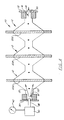
- a typical sensor of this type is shown in simplified form in Figure 1.
- the sensor generally indicated at 10, comprises a series of cells, generally indicated as 12, which define a path for the flow of test fluid 14 therethrough between the inlet at 16 and the outlet at 18. While a single cell 12 can be used, it is common to place a number of cells 12 in series to develop a larger electrical signal to more accurately reflect the characteristics of the test fluid 14.
- Each cell 12 typically contains a porous detector electrode 20 across the path of flow of the test fluid 14 through the cell 12. It is the detector electrode 20 in each cell 12 which develops the electrical signal of interest as the test fluid 14 passes through it.
- the detector electrode 20 is comprised of a porous electrode base material 22 such as fritted graphite or fritted carbon with pores 23.
- the porous material 22 in turn contains intersticial spaces 24 in the underlying matrix of the porous material 22. Since it is virtually impossible to create a homogeneous fritt material wherein the intersticial spaces 24 are completely uniform throughout the porous material 22 also may contain enlarged secondary pores 26. Characteristically, the fluid 14 will find an optimum path through the cells 12 of the sensor 10. These enlarged secondary pores 26 and interstitial spaces 24 can be a source of noise, particularly when they are out of the optimum path and, therefore, not contributing in any substantial manner to the signal of interest being developed.
- junctions and traps in the construction of the sensor 10, such as those generally indicated at 28, can reduce the bandspreading of the cells 12 by inducing drag and trapping effects on the test fluid 14.
- the invention provides a method as defined in Claim 1 below.
- the setting fluid is a meltable polymer loaded at or above its melt temperature which will cool to a solid; and the method additionally comprises the step of, with the immiscible fluid in the cell, cooling the cell to solidify the melted polymer.
- the cell may then be used directly. Alternatively and preferably the cell is then rinsed with a fluid that etches the surface of the polymer deposited along the optimum path to expose any residual polymer covering the active surface of the detector in the optimum path.
- the basic premise of the present invention is set forth in the block diagram of Figure 3.
- the cells 12 are first loaded with a first fluid material which is "settable” to a solid, and a second fluid immiscible with the first fluid then is passed through the cells.
- the second fluid "finds” or defines the optimum flow path through the cells, and sweeps the first fluid from this path.
- the first fluid then is solidified resulting in a sensor with the optimum flow path exposed to test fluid passing therethrough and the irregularities which contribute to the problems described above masked from interference by the solidified material.
- the settable fluid can be a material of the type that will turn to a solid after a time delay such as an epoxy, phenol-formaldehyde or styrene monomer.
- the setting fluid can be a meltable material loaded at or above its melt temperature which upon cooling will form a solid such as a naturally occurring or synthetic wax, or a meltable polymeric material such as polyethylene or polypropylene.
- the setting fluid also may be a thermal setting polymer, many of which are commercially available. The specific examples set forth herein will be with respect to the use of meltable polymeric materials.
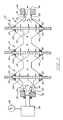
- a melted polymeric material 30 is forced through the cells 12 under high pressure. This can be accomplished by closing down the outlet 18 with a plate 32 having a reduced orifice opening 34 therethrough.
- the inlet 16 is likewise closed down with a plate 36 having a nozzle 38 therethrough connected to a source 40 of the melted polymeric material 30 under a high pressure as indicated by the pressure gauge 42.
- the material 30 is forced into all the junction and trap areas 28 as well as into the secondary inherent pores 26 of the porous electrodes 20A, 20B, 20C.
- a fluid 44 immiscible with the melted polymeric material 30 is next pumped from source 46 through the cells 12 and porous electrodes 20A, 20B, 20C.
- the flow volume is adjusted to substantially equal or slightly exceed that intended for the flow of test fluid through the sensor 10 under actual use.
- This step results in the fluid 44 seeking out and defining the optimum path for flow through the sensor 10.
- the fluid 44 passing through the sensor 10, being immiscible with the melted polymeric material 30 flushes the fluid polymeric material 30 along the optimum path from the sensor 10 while leaving the polymeric material 30 in the remaining areas essentially undisturbed.
- the flow of the immiscible fluid 44 be maintained while the polymeric material 30 is allowed to solidify.
- the fluid 44 can be maintained statically within the sensor 10, cells 12, and detectors 20, e.g. as by closing off the inlet 16 and outlet 18 while solidification takes places.
- the cell may then be flushed and put into service. It is preferred, however, that subsequent to the solidification of the polymeric material 30, to flush the sensor 10 with an etching fluid which will remove any residual polymeric material 30 along the walls of the optimum path which was not flushed out by the passage of the immiscible fluid 44. This step simply assures that the maximum active surface of the porous detector electrodes in the optimum path will be available to generate the signal as a result of the test fluid 14 passing therethrough.
- the result of the foregoing process leaves the sensor 10 as shown in use in Figure 6.
- the solidified polymeric material 30 remains in the areas off of the optimum path to eliminate the problems previously associated therewith while the test fluid 14 is free to flow unhampered along the optimum path. More specifically, the process accomplishes several things:
- the sensor treated was a multiple electrode flow cell as described in Fig. 1 of my prior U.S. Patent 4,511,659.
- a melted polymer mixture comprising 67 volume percent C48 hydrocarbon and 33 volume percent 0.916 density polyethylene, heated to 98°C was pumped into the cell at 56 kg.cm ⁇ 2 (800 psi). Thereafter, water heated to 98°C was passed through the cell at 0.1 mL/min at 1.4 kg.cm ⁇ 2 (20 psi). The cell was then cooled from 98°C to ambient (25°C) over a 15 minute time period by continuing the flow of cooler and cooler water.
- Disassembly of the cell following testing showed the retention of the solidified polymeric material at various locations 30. From performance testing of the cell polymeric material retention also was inferred at various intersticial spaces in the underlying matrix of the porous electrodes.
- BEFORE AFTER Efficiency of the first in line electrode 20A to hydroquinone 99.7% 99.7% Efficiency of second in line electrode 20B to hydroquinone 99.3% 99.4% Bandspreading electrode 20A ( ⁇ l at 13.7% peak height) 37.3 17.8 Bandspreading electrode 20B ( ⁇ l at 13.7% peak height) 38.1 18.3 Signal at electrode 20B to 10 pg Norepinephrine, Condition 1 1.8 na 1.8 na Noise at electrode 20B Condition 1 0.7 na 0.2 na Background Current at electrode 20B -11 na -12 na Signal at electrode 20B to 100 pg histamine, Condition 2 7.2 na 7.4 na Noise at electrode 20B, Condition 2 3.2 na 0.4 na Background Current at electrode 20B 16 ⁇ a 0.8 ⁇ a
- the noise and background current reduction results again from blocking the unused portions of the porous electrode substrate material and filling the secondary matrix pores.
- the noise reduction more substantial than in the first operating condition, is believed to result from a different mechanism. More particularly, under the second operating condition, currents in the anodic potential region are observed primarily from the beginning of the wave of oxidation of the carrier mobile phase itself and are virtually completely potential limited rather than diffusion limited. Thus, when the spaces and pores are not filled, they may be penetrated to a greater or lesser extent by the mobile phase. Accordingly, the total area of the sensor including non-flow regions and pores is the area available for background signal noise. Noise can then be caused by changes in the area by pressure variation or potential fluctuations, which each linearly affect the observed currents. Filling or masking these regions presents a substantially lower area for potential limited mobile phase reactions while not impacting significantly the area for diffusion limited reactions that constitute the analytical signal.
- the invention is susceptible to modification.
- a liquid monomer may be loaded into the cell under pressure. Thereafter, an immiscible liquid containing a polymerization activator may be flowed through the cell under low pressure to achieve the dual purposes of defining the optimal flow path and effecting polymerization of the monomer to a solid. Still other changes and advantages will be obvious to one skilled in the art.
Landscapes
- Chemical & Material Sciences (AREA)
- Life Sciences & Earth Sciences (AREA)
- Health & Medical Sciences (AREA)
- General Physics & Mathematics (AREA)
- Pathology (AREA)
- Electrochemistry (AREA)
- Physics & Mathematics (AREA)
- Analytical Chemistry (AREA)
- Biochemistry (AREA)
- General Health & Medical Sciences (AREA)
- Molecular Biology (AREA)
- Immunology (AREA)
- Chemical Kinetics & Catalysis (AREA)
- Investigating Or Analyzing Materials By The Use Of Ultrasonic Waves (AREA)
- Investigating Or Analyzing Materials By The Use Of Electric Means (AREA)
- Optical Measuring Cells (AREA)
- Investigating Or Analysing Materials By Optical Means (AREA)
- Investigating Or Analyzing Materials Using Thermal Means (AREA)
- Radar Systems Or Details Thereof (AREA)
- Ultra Sonic Daignosis Equipment (AREA)
Claims (10)
- Verfahren zur Optimierung des Stroemungsverhaltens und des Geraeuschabstandes einer Stroemung in einem mit mindestens einer durch ein zu analysierendes Medium durgechflossenen Zelle (12) und mit einer poroesen Spuerelektrode versehenen Messfuehler, durch welche das zu analysierende Medium gefuehrt wird,
dadurch gekennzeichnet dass es folgende Vorgaenge aufweist :(a) Zelle mit einem unter einem zum Vollfuellen mittels des Mediums aller in der Zelle und der Elektrode vorhandenen Hohlraeumen (26), Poren (23) und Unregelmaessigkeiten (28) genug hohen ersten Druck zu einem festen Material härtbaren Material fuellen ;(b) vor dem Festwerden des Mediums ein mit dem haertbaren Medium nicht mischbares Medium unter einem unter dem ersten Druck liegenden Druck so fliessen lassen dass durch diese ein optimaler Stroeumungsweg bestimmt wird und dass das haertbares Medium aus diesem Stroemungsweg entfernt wird ; und(c) in dem das nicht mischbare Medium in der Zelle vorhanden ist, das haertbare Medium in allen ausser dieses Stroemungsweges liegenden Hohlraeumen, Poren und Unregelmaessigkeiten erhaerten lassen. - Verfahren nach Anspruch 1 dadurch gekennzeichnet dass es ein oder mehrere der Folgenden Kennzeichen aufweist :(a) das nicht mischbare Medium wird statisch in der Zelle wachrend der Aushaertung des haertbaren Mediums gehalten ;(b) das nicht mischbare Medium wird waehrend der Aushaertung des nicht mischbaren Mediums unter Stroemungsbedingungen gehalten ;(c) das nicht mischbare Medium wird unter einem zwischen 42 und 112 kg/cm² (600 und 16000 p.s.i.) in die Zelle eingefuehrt.
- Verfahren nach Anspruch 1 oder 2, dadurch gekennzeichnet dass das haertbare Medium einer Type gehoert die zu einem festen Stoff nach einer bestimmten Zeitspanne wird, und vorzugsweise ein Epoxydharz, ein Phenolformaldehydharz oder Monomerstyrol ist.
- Verfahren nach Anspruch 1 oder 2, dadurch gekennzeichnet dass das haertbare Medium ein schmelzbares Material, vorzugsweise Paraffin, Polyaethylen, Polypropylen oder ein Gemisch von zwei oder drei der vorgenannten Materialien, das zu seiner Schmelztemperatur oder zu einer hoeheren Temperatur eingefuehrt wird ; und dass es zuzaetzlich einen Vorgang enthaelt in welchem das haertbare Medium waehrend des Fliessens des nicht mïschbaren Mediums (44) durch die Zelle zu seiner Schmelztemperatur oder zu einer hoeheren Temperatur gehalten wird.
- Verfahren nach Anspruch 1, 2 oder 4, dadurch gekennzeichnet dass das haertbare Medium ein schmelzbares, zu seiner Schmelztemperatur, oder zu einer hoeheren Temperatur eingefuehrtes, Polymer ist und dass es zusaetzlich einen Vorgang enthaelt in welchem die das nicht mischbare Medium (44) beinhaltende Zelle gekuehlt wird, um das geschmolzene Polymer erhaerten zu lassen.
- Verfahren nach Anspruch 1 oder 2, dadurch gekennzeichnet dass das haertbare Medium ein waermehaertendes Polymer ist ; und dass es zusaetzlich einen Vorgang enthaelt in welchem, indem das nicht mischbare Medium in der Zelle vorhanden ist, das genannte Polymer erwaermt wird, um es erhaerten zu lassen.
- Verfahren nach Anspruch 5 oder 6, dadurch gekennzeichnet dass es zusaetzlich den folgenden Vorgang enthaelt :- Spuelen der Zelle mittels eines Mediums das die Oberflaeche des abgelagerten Polymers aetzend angreift wodurch das an den Waenden des optimalen Weges verbleibende Polymer entfernt wird.
- Verfahren nach Anspruch 5, dadurch gekennzeichnet dass es zusaetzlich einen Vorgang enthaelt in welchem die Zelle mittels eines aetzenden Mediums zwecks Entfernung aller Filme und Ruekstaende vom erhaerteten Polymer kraeftig durchgestroemt wird.
- Verfahren nach Anspruch 5, dadurch gekennzeichnet dass(a) das schmelzbare Polymer ein zu seiner Schmelztemperatur und unter einem Druck von 56 kg.cm⁻² (800 p.s.i.) stehendes Gemisch von einem Kohlenwasserstoff und Polyaethylen ist ;(b) das nicht mischbare Medium zu einer der Schmelztemperatur des durch die Zelle fliessenden Gemisches entsprechenden, oder einer hoeheren Temperatur, und mit einem Durchsatz von 0,1 mL/min. und unter einem Druck von etwa 1,4 kg.cm⁻² (20 p.s.i.) stehendes Wasser ist(c) der Kuehlvorgang zur Kuehlung der Zelle unter der Schmelztemperatur des Gemisches fuehrt.
- Verfahren nach Anspruch 1, dadurch gekennzeichnet dass es zusaetzlich einen Vorgang enthaelt in welchem die Zelle mittels eines Mediums gespuelt wird welches die Oberflaeche des abgelagerten erhaerteten haertbaren Mediums aetzend angreift, wodurch das an den Waenden des optimalen Weges verbleibende erhaertete haertbare Medium entfernt wird.
Priority Applications (1)
| Application Number | Priority Date | Filing Date | Title |
|---|---|---|---|
| AT86308743T ATE67855T1 (de) | 1985-11-13 | 1986-11-11 | Verfahren zur optimierung von stroemungsbildern und zum vergroessern von signal/geraeuschverh|ltnissen in elektrochemischen durchflusssensoren. |
Applications Claiming Priority (2)
| Application Number | Priority Date | Filing Date | Title |
|---|---|---|---|
| US79761685A | 1985-11-13 | 1985-11-13 | |
| US797616 | 1985-11-13 |
Publications (3)
| Publication Number | Publication Date |
|---|---|
| EP0223532A2 EP0223532A2 (de) | 1987-05-27 |
| EP0223532A3 EP0223532A3 (en) | 1988-06-01 |
| EP0223532B1 true EP0223532B1 (de) | 1991-09-25 |
Family
ID=25171334
Family Applications (1)
| Application Number | Title | Priority Date | Filing Date |
|---|---|---|---|
| EP86308743A Expired EP0223532B1 (de) | 1985-11-13 | 1986-11-11 | Verfahren zur Optimierung von Strömungsbildern und zum Vergrössern von Signal/Geräusch-Verhältnissen in elektrochemischen Durchflusssensoren |
Country Status (6)
| Country | Link |
|---|---|
| US (1) | US4753714A (de) |
| EP (1) | EP0223532B1 (de) |
| JP (1) | JPH0785068B2 (de) |
| AT (1) | ATE67855T1 (de) |
| CA (1) | CA1238362A (de) |
| DE (1) | DE3681691D1 (de) |
Families Citing this family (3)
| Publication number | Priority date | Publication date | Assignee | Title |
|---|---|---|---|---|
| US5254235A (en) * | 1992-02-26 | 1993-10-19 | The Yellow Springs Instrument Company | Microelectrode arrays |
| US20070170056A1 (en) * | 2006-01-26 | 2007-07-26 | Arnold Don W | Microscale electrochemical cell and methods incorporating the cell |
| US20080182136A1 (en) * | 2007-01-26 | 2008-07-31 | Arnold Don W | Microscale Electrochemical Cell And Methods Incorporating The Cell |
Family Cites Families (6)
| Publication number | Priority date | Publication date | Assignee | Title |
|---|---|---|---|---|
| US1736293A (en) * | 1927-12-14 | 1929-11-19 | John W Van Denburg | Method and apparatus for repairing leaky conduits |
| US2962768A (en) * | 1957-07-15 | 1960-12-06 | Phillips Petroleum Co | Method of producing solid void-free articles of thermoplastic resins |
| US4233031A (en) * | 1978-12-11 | 1980-11-11 | Environmental Sciences Associates, Inc. | Electrochemical testing system and method |
| US4404065A (en) * | 1980-01-14 | 1983-09-13 | Enviromental Sciences Associates, Inc. | Electrochemical detection system and method of analysis |
| US4511659A (en) * | 1983-03-04 | 1985-04-16 | Esa, Inc. | Liquid chromatograph with electrochemical detector and method |
| JPS59212757A (ja) * | 1983-05-19 | 1984-12-01 | Toshiba Corp | 流通型イオンセンサ体 |
-
1986
- 1986-11-11 AT AT86308743T patent/ATE67855T1/de not_active IP Right Cessation
- 1986-11-11 DE DE8686308743T patent/DE3681691D1/de not_active Expired - Lifetime
- 1986-11-11 EP EP86308743A patent/EP0223532B1/de not_active Expired
- 1986-11-12 CA CA000522778A patent/CA1238362A/en not_active Expired
- 1986-11-13 JP JP61270827A patent/JPH0785068B2/ja not_active Expired - Fee Related
-
1987
- 1987-08-10 US US07/085,324 patent/US4753714A/en not_active Expired - Fee Related
Also Published As
| Publication number | Publication date |
|---|---|
| EP0223532A3 (en) | 1988-06-01 |
| ATE67855T1 (de) | 1991-10-15 |
| EP0223532A2 (de) | 1987-05-27 |
| DE3681691D1 (de) | 1991-10-31 |
| JPH0785068B2 (ja) | 1995-09-13 |
| JPS62127664A (ja) | 1987-06-09 |
| US4753714A (en) | 1988-06-28 |
| CA1238362A (en) | 1988-06-21 |
Similar Documents
| Publication | Publication Date | Title |
|---|---|---|
| Cheng et al. | Ultramicroelectrode ensembles. Comparison of experimental and theoretical responses and evaluation of electroanalytical detection limits | |
| Wallingford et al. | Separation of serotonin from catechols by capillary zone electrophoresis with electrochemical detection | |
| DE3752278T2 (de) | Verfahren für elektrochemische Messungen | |
| Rucki | Electrochemical detectors for flowing liquid systems | |
| Shropshire | The catalysis of the electrochemical oxidation of formaldehyde and methanol by molybdates | |
| Walcarius | Factors affecting the analytical applications of zeolite modified electrodes: indirect detection of nonelectroactive cations | |
| Deinhammer et al. | Retention characteristics of polypyrrole as a stationary phase for the electrochemically modulated liquid chromatographic (EMLC) separations of dansyl amino acids | |
| EP0223532B1 (de) | Verfahren zur Optimierung von Strömungsbildern und zum Vergrössern von Signal/Geräusch-Verhältnissen in elektrochemischen Durchflusssensoren | |
| Francois et al. | Separation of transition metal cations by capillary electrophoresis optimization of complexing agent concentrations (lactic acid and 18-crown-6) | |
| Bond et al. | The analytical performance of direct current, normal pulse and differential pulse polarography with static mercury drop electrodes | |
| Guerra et al. | Experimental optimization of selective hydrazine detection in flow injection analysis using a carbon paste electrode modified with copper porphyrin occluded into zeolite cavity | |
| Wang et al. | Potential scanning voltammetric detection for flow injection systems | |
| DE68921937T2 (de) | Steuerung bzw. Kontrolle des elektrokinetischen Potentials durch Behandlung mit Redoxmitteln. | |
| Pournaghi-Azar et al. | Adsorptive pulse polarographic determination of uranium (VI) oxinate in chloroform and its use for the analysis of uranium mineral ores | |
| Trudgill et al. | Soil-water residence time and solute uptake: 2. Dye tracing and preferential flow predictions | |
| Wang et al. | Background-current subtraction in voltammetric detection for flow-injection analysis | |
| US5733437A (en) | Method for detecting small molecules in aqueous liquids | |
| Lee et al. | Determination of total arsenic species by anodic stripping voltammetry | |
| Wang | Anodic stripping voltammetry at graphite-epoxy microelectrodes for in vitro and in vivo measurements of trace metals | |
| Zhao et al. | Adsorption voltammetry of the copper-4-[(4-diethylamino-2-hydroxyphenyl) azo]-5-hydroxynaphthalene-2, 7-disulphonic acid (Beryllon III) system | |
| DE4315749A1 (de) | Elektrochemischer Sensor mit einem Festelektrolyten zur Messung der Gaskonzentration | |
| Cox et al. | Selective electrocatalytic method for the determination of nitrite | |
| Jansta et al. | Electrochemical systems for galvanic cells in organic aprotic solvents: III. Quantitative evaluation of electrochemical effects of trace water in KPF6-propylene carbonate electrolyte | |
| Mayell | Kinetics of the Chemical and Electrochemical Reduction of Platinum Black Surface Oxides | |
| Gunasingham et al. | Differential pulse anodic stripping voltammetry at the wall-jet electrode |
Legal Events
| Date | Code | Title | Description |
|---|---|---|---|
| PUAI | Public reference made under article 153(3) epc to a published international application that has entered the european phase |
Free format text: ORIGINAL CODE: 0009012 |
|
| AK | Designated contracting states |
Kind code of ref document: A2 Designated state(s): AT BE CH DE ES FR GB IT LI NL SE |
|
| PUAL | Search report despatched |
Free format text: ORIGINAL CODE: 0009013 |
|
| AK | Designated contracting states |
Kind code of ref document: A3 Designated state(s): AT BE CH DE ES FR GB IT LI NL SE |
|
| 17P | Request for examination filed |
Effective date: 19881121 |
|
| 17Q | First examination report despatched |
Effective date: 19900529 |
|
| GRAA | (expected) grant |
Free format text: ORIGINAL CODE: 0009210 |
|
| AK | Designated contracting states |
Kind code of ref document: B1 Designated state(s): AT BE CH DE ES FR GB IT LI NL SE |
|
| PG25 | Lapsed in a contracting state [announced via postgrant information from national office to epo] |
Ref country code: SE Effective date: 19910925 Ref country code: NL Effective date: 19910925 Ref country code: BE Effective date: 19910925 Ref country code: AT Effective date: 19910925 |
|
| REF | Corresponds to: |
Ref document number: 67855 Country of ref document: AT Date of ref document: 19911015 Kind code of ref document: T |
|
| ITF | It: translation for a ep patent filed | ||
| REF | Corresponds to: |
Ref document number: 3681691 Country of ref document: DE Date of ref document: 19911031 |
|
| ET | Fr: translation filed | ||
| PG25 | Lapsed in a contracting state [announced via postgrant information from national office to epo] |
Ref country code: ES Free format text: LAPSE BECAUSE OF FAILURE TO SUBMIT A TRANSLATION OF THE DESCRIPTION OR TO PAY THE FEE WITHIN THE PRESCRIBED TIME-LIMIT Effective date: 19920105 |
|
| NLV1 | Nl: lapsed or annulled due to failure to fulfill the requirements of art. 29p and 29m of the patents act | ||
| PLBE | No opposition filed within time limit |
Free format text: ORIGINAL CODE: 0009261 |
|
| STAA | Information on the status of an ep patent application or granted ep patent |
Free format text: STATUS: NO OPPOSITION FILED WITHIN TIME LIMIT |
|
| 26N | No opposition filed | ||
| PGFP | Annual fee paid to national office [announced via postgrant information from national office to epo] |
Ref country code: FR Payment date: 19931011 Year of fee payment: 8 |
|
| PGFP | Annual fee paid to national office [announced via postgrant information from national office to epo] |
Ref country code: CH Payment date: 19931014 Year of fee payment: 8 |
|
| PGFP | Annual fee paid to national office [announced via postgrant information from national office to epo] |
Ref country code: DE Payment date: 19931022 Year of fee payment: 8 |
|
| PGFP | Annual fee paid to national office [announced via postgrant information from national office to epo] |
Ref country code: GB Payment date: 19931028 Year of fee payment: 8 |
|
| PG25 | Lapsed in a contracting state [announced via postgrant information from national office to epo] |
Ref country code: GB Effective date: 19941111 |
|
| PG25 | Lapsed in a contracting state [announced via postgrant information from national office to epo] |
Ref country code: LI Effective date: 19941130 Ref country code: CH Effective date: 19941130 |
|
| GBPC | Gb: european patent ceased through non-payment of renewal fee |
Effective date: 19941111 |
|
| PG25 | Lapsed in a contracting state [announced via postgrant information from national office to epo] |
Ref country code: FR Effective date: 19950731 |
|
| REG | Reference to a national code |
Ref country code: CH Ref legal event code: PL |
|
| PG25 | Lapsed in a contracting state [announced via postgrant information from national office to epo] |
Ref country code: DE Effective date: 19950801 |
|
| REG | Reference to a national code |
Ref country code: FR Ref legal event code: ST |
|
| PG25 | Lapsed in a contracting state [announced via postgrant information from national office to epo] |
Ref country code: IT Free format text: LAPSE BECAUSE OF NON-PAYMENT OF DUE FEES;WARNING: LAPSES OF ITALIAN PATENTS WITH EFFECTIVE DATE BEFORE 2007 MAY HAVE OCCURRED AT ANY TIME BEFORE 2007. THE CORRECT EFFECTIVE DATE MAY BE DIFFERENT FROM THE ONE RECORDED. Effective date: 20051111 |