EP0227084B1 - Filtre-presse - Google Patents
Filtre-presse Download PDFInfo
- Publication number
- EP0227084B1 EP0227084B1 EP86117862A EP86117862A EP0227084B1 EP 0227084 B1 EP0227084 B1 EP 0227084B1 EP 86117862 A EP86117862 A EP 86117862A EP 86117862 A EP86117862 A EP 86117862A EP 0227084 B1 EP0227084 B1 EP 0227084B1
- Authority
- EP
- European Patent Office
- Prior art keywords
- filter
- rotor
- filter press
- housing
- casing
- Prior art date
- Legal status (The legal status is an assumption and is not a legal conclusion. Google has not performed a legal analysis and makes no representation as to the accuracy of the status listed.)
- Expired
Links
- 239000000706 filtrate Substances 0.000 claims abstract description 18
- 238000007789 sealing Methods 0.000 claims description 26
- 239000012530 fluid Substances 0.000 claims description 14
- 230000002093 peripheral effect Effects 0.000 claims description 6
- 238000006073 displacement reaction Methods 0.000 claims description 2
- 210000004262 dental pulp cavity Anatomy 0.000 claims 3
- 239000012065 filter cake Substances 0.000 description 17
- 239000002002 slurry Substances 0.000 description 12
- 238000004140 cleaning Methods 0.000 description 8
- 239000010802 sludge Substances 0.000 description 6
- 238000010276 construction Methods 0.000 description 5
- 239000000463 material Substances 0.000 description 4
- 238000003825 pressing Methods 0.000 description 4
- 238000011010 flushing procedure Methods 0.000 description 3
- 239000007788 liquid Substances 0.000 description 3
- 239000012528 membrane Substances 0.000 description 3
- 238000000034 method Methods 0.000 description 3
- 230000008569 process Effects 0.000 description 3
- 238000011001 backwashing Methods 0.000 description 2
- 230000008901 benefit Effects 0.000 description 2
- 230000003749 cleanliness Effects 0.000 description 2
- 239000000356 contaminant Substances 0.000 description 2
- 239000004744 fabric Substances 0.000 description 2
- 238000012423 maintenance Methods 0.000 description 2
- 239000002184 metal Substances 0.000 description 2
- 239000004033 plastic Substances 0.000 description 2
- 238000005406 washing Methods 0.000 description 2
- XLYOFNOQVPJJNP-UHFFFAOYSA-N water Substances O XLYOFNOQVPJJNP-UHFFFAOYSA-N 0.000 description 2
- 230000004323 axial length Effects 0.000 description 1
- 239000011324 bead Substances 0.000 description 1
- 238000011109 contamination Methods 0.000 description 1
- 230000008878 coupling Effects 0.000 description 1
- 238000010168 coupling process Methods 0.000 description 1
- 238000005859 coupling reaction Methods 0.000 description 1
- 230000003247 decreasing effect Effects 0.000 description 1
- 239000000945 filler Substances 0.000 description 1
- 238000001914 filtration Methods 0.000 description 1
- 239000010720 hydraulic oil Substances 0.000 description 1
- 239000012535 impurity Substances 0.000 description 1
- 238000003754 machining Methods 0.000 description 1
- 238000004519 manufacturing process Methods 0.000 description 1
- 230000007246 mechanism Effects 0.000 description 1
- 230000035515 penetration Effects 0.000 description 1
- 238000001556 precipitation Methods 0.000 description 1
- 230000009467 reduction Effects 0.000 description 1
- 239000007787 solid Substances 0.000 description 1
- 239000007921 spray Substances 0.000 description 1
- 238000009827 uniform distribution Methods 0.000 description 1
- 238000009423 ventilation Methods 0.000 description 1
- 238000003466 welding Methods 0.000 description 1
Images


Classifications
-
- B—PERFORMING OPERATIONS; TRANSPORTING
- B01—PHYSICAL OR CHEMICAL PROCESSES OR APPARATUS IN GENERAL
- B01D—SEPARATION
- B01D37/00—Processes of filtration
- B01D37/02—Precoating the filter medium; Addition of filter aids to the liquid being filtered
-
- B—PERFORMING OPERATIONS; TRANSPORTING
- B01—PHYSICAL OR CHEMICAL PROCESSES OR APPARATUS IN GENERAL
- B01D—SEPARATION
- B01D29/00—Filters with filtering elements stationary during filtration, e.g. pressure or suction filters, not covered by groups B01D24/00 - B01D27/00; Filtering elements therefor
- B01D29/39—Filters with filtering elements stationary during filtration, e.g. pressure or suction filters, not covered by groups B01D24/00 - B01D27/00; Filtering elements therefor with hollow discs side by side on, or around, one or more tubes, e.g. of the leaf type
-
- B—PERFORMING OPERATIONS; TRANSPORTING
- B01—PHYSICAL OR CHEMICAL PROCESSES OR APPARATUS IN GENERAL
- B01D—SEPARATION
- B01D29/00—Filters with filtering elements stationary during filtration, e.g. pressure or suction filters, not covered by groups B01D24/00 - B01D27/00; Filtering elements therefor
- B01D29/50—Filters with filtering elements stationary during filtration, e.g. pressure or suction filters, not covered by groups B01D24/00 - B01D27/00; Filtering elements therefor with multiple filtering elements, characterised by their mutual disposition
- B01D29/52—Filters with filtering elements stationary during filtration, e.g. pressure or suction filters, not covered by groups B01D24/00 - B01D27/00; Filtering elements therefor with multiple filtering elements, characterised by their mutual disposition in parallel connection
- B01D29/54—Filters with filtering elements stationary during filtration, e.g. pressure or suction filters, not covered by groups B01D24/00 - B01D27/00; Filtering elements therefor with multiple filtering elements, characterised by their mutual disposition in parallel connection arranged concentrically or coaxially
-
- B—PERFORMING OPERATIONS; TRANSPORTING
- B01—PHYSICAL OR CHEMICAL PROCESSES OR APPARATUS IN GENERAL
- B01D—SEPARATION
- B01D29/00—Filters with filtering elements stationary during filtration, e.g. pressure or suction filters, not covered by groups B01D24/00 - B01D27/00; Filtering elements therefor
- B01D29/62—Regenerating the filter material in the filter
- B01D29/64—Regenerating the filter material in the filter by scrapers, brushes, nozzles, or the like, acting on the cake side of the filtering element
- B01D29/6469—Regenerating the filter material in the filter by scrapers, brushes, nozzles, or the like, acting on the cake side of the filtering element scrapers
- B01D29/6476—Regenerating the filter material in the filter by scrapers, brushes, nozzles, or the like, acting on the cake side of the filtering element scrapers with a rotary movement with respect to the filtering element
-
- B—PERFORMING OPERATIONS; TRANSPORTING
- B01—PHYSICAL OR CHEMICAL PROCESSES OR APPARATUS IN GENERAL
- B01D—SEPARATION
- B01D29/00—Filters with filtering elements stationary during filtration, e.g. pressure or suction filters, not covered by groups B01D24/00 - B01D27/00; Filtering elements therefor
- B01D29/62—Regenerating the filter material in the filter
- B01D29/66—Regenerating the filter material in the filter by flushing, e.g. counter-current air-bumps
-
- B—PERFORMING OPERATIONS; TRANSPORTING
- B01—PHYSICAL OR CHEMICAL PROCESSES OR APPARATUS IN GENERAL
- B01D—SEPARATION
- B01D29/00—Filters with filtering elements stationary during filtration, e.g. pressure or suction filters, not covered by groups B01D24/00 - B01D27/00; Filtering elements therefor
- B01D29/76—Handling the filter cake in the filter for purposes other than for regenerating
- B01D29/80—Handling the filter cake in the filter for purposes other than for regenerating for drying
- B01D29/82—Handling the filter cake in the filter for purposes other than for regenerating for drying by compression
- B01D29/822—Handling the filter cake in the filter for purposes other than for regenerating for drying by compression using membranes
-
- B—PERFORMING OPERATIONS; TRANSPORTING
- B01—PHYSICAL OR CHEMICAL PROCESSES OR APPARATUS IN GENERAL
- B01D—SEPARATION
- B01D29/00—Filters with filtering elements stationary during filtration, e.g. pressure or suction filters, not covered by groups B01D24/00 - B01D27/00; Filtering elements therefor
- B01D29/76—Handling the filter cake in the filter for purposes other than for regenerating
- B01D29/80—Handling the filter cake in the filter for purposes other than for regenerating for drying
- B01D29/82—Handling the filter cake in the filter for purposes other than for regenerating for drying by compression
- B01D29/824—Handling the filter cake in the filter for purposes other than for regenerating for drying by compression using pistons
-
- B—PERFORMING OPERATIONS; TRANSPORTING
- B01—PHYSICAL OR CHEMICAL PROCESSES OR APPARATUS IN GENERAL
- B01D—SEPARATION
- B01D29/00—Filters with filtering elements stationary during filtration, e.g. pressure or suction filters, not covered by groups B01D24/00 - B01D27/00; Filtering elements therefor
- B01D29/76—Handling the filter cake in the filter for purposes other than for regenerating
- B01D29/80—Handling the filter cake in the filter for purposes other than for regenerating for drying
- B01D29/84—Handling the filter cake in the filter for purposes other than for regenerating for drying by gases or by heating
- B01D29/843—Handling the filter cake in the filter for purposes other than for regenerating for drying by gases or by heating by direct contact with a fluid
-
- B—PERFORMING OPERATIONS; TRANSPORTING
- B01—PHYSICAL OR CHEMICAL PROCESSES OR APPARATUS IN GENERAL
- B01D—SEPARATION
- B01D29/00—Filters with filtering elements stationary during filtration, e.g. pressure or suction filters, not covered by groups B01D24/00 - B01D27/00; Filtering elements therefor
- B01D29/76—Handling the filter cake in the filter for purposes other than for regenerating
- B01D29/86—Retarding cake deposition on the filter during the filtration period, e.g. using stirrers
-
- B—PERFORMING OPERATIONS; TRANSPORTING
- B01—PHYSICAL OR CHEMICAL PROCESSES OR APPARATUS IN GENERAL
- B01D—SEPARATION
- B01D36/00—Filter circuits or combinations of filters with other separating devices
- B01D36/001—Filters in combination with devices for the removal of gas, air purge systems
-
- B—PERFORMING OPERATIONS; TRANSPORTING
- B30—PRESSES
- B30B—PRESSES IN GENERAL
- B30B9/00—Presses specially adapted for particular purposes
- B30B9/02—Presses specially adapted for particular purposes for squeezing-out liquid from liquid-containing material, e.g. juice from fruits, oil from oil-containing material
- B30B9/04—Presses specially adapted for particular purposes for squeezing-out liquid from liquid-containing material, e.g. juice from fruits, oil from oil-containing material using press rams
- B30B9/045—Presses specially adapted for particular purposes for squeezing-out liquid from liquid-containing material, e.g. juice from fruits, oil from oil-containing material using press rams co-operating with several adjacent casings
-
- B—PERFORMING OPERATIONS; TRANSPORTING
- B30—PRESSES
- B30B—PRESSES IN GENERAL
- B30B9/00—Presses specially adapted for particular purposes
- B30B9/02—Presses specially adapted for particular purposes for squeezing-out liquid from liquid-containing material, e.g. juice from fruits, oil from oil-containing material
- B30B9/22—Presses specially adapted for particular purposes for squeezing-out liquid from liquid-containing material, e.g. juice from fruits, oil from oil-containing material using a flexible member, e.g. diaphragm, urged by fluid pressure
Definitions
- the invention relates to a filter press according to the preamble of claim 1.
- a filter press is known from US-A 2 975 903.
- the filter press described in this document consists of a bottom-supported housing of essentially cylindrical cross section, the jacket of which is closed at one end by a fixed end wall and at the other end by an axially displaceable end wall.
- a running rail is attached to the casing, on which a carriage is slidably guided and carries the movable end wall.
- a frame is attached to the movable end wall within the housing and extends into the housing in the axial direction and carries a plurality of filter frames arranged axially one behind the other and parallel to one another. At the end facing away from the movable end wall, the frame has rollers which run on rails which are fastened to the inner side walls of the housing shell.
- the frame is essentially formed by pipes which are used to discharge filtrate from the filtrate chambers each enclosed by the filter frame.
- the filter press has the disadvantages inherent in all filter presses with insufficient turbidity movement, in particular the rapid settling of solids on the filter aids, which leads to a rapid reduction in the turbidity throughput. Since opening the filter press and removing the filter cake based on the filter aids is complicated and time-consuming due to the construction explained, the overall result of this filter press is only low.
- EPC also includes a filter press, which is described in EP-A 0 178 389.
- This contains a plurality of filter units arranged axially one behind the other, each consisting of a filter frame and a plate-shaped rotor disk opposite this, which is attached in a rotationally fixed manner to a hollow shaft passing through the filter press.
- the filter frame contains a cavity, which is covered on the side opposite the rotor disk by a filter aid in the form of a perforated plate, a filter cloth or the like, which may be supported by ribs in the aforementioned cavity. From the cavity, which receives the filtrate, an essentially radially extending channel leads into a circumferential groove formed on the filter frame.
- the frame is sealed by means of 0-rings on a housing jacket surrounding all filter units, from which filtrate outlets lead to the outside. These seals are necessary to seal the filtrate outlet of one filter unit against the turbidity chamber of the neighboring filter unit.
- the sludge to be filtered is introduced into the sludge chambers and distributed therein by means of the rotor disks, the rotor disks ensuring a slow build-up of the filter cake on the filtrate auxiliaries. After achieving a sufficient filter cake thickness, the filter cakes are pressed out with the help of the rotor disks in order to drain them as best as possible.
- the housing jacket is pulled off the turbidity chambers in the axial direction, so that the filter cake can be removed from the filter press in the radial direction. This is done with the support of the rotor disks, which have a clearing rib and are set in rotation.
- this filter press still leaves some wishes unfulfilled.
- the seals mentioned which seal the filtrate chambers against the turbidity chambers, have to withstand a relatively high pressure difference.
- a pulling movement takes place over the large number of existing seals, which is not only harmful for these seals, but also requires considerable effort.
- the seals come into contact with the filter residues when cleaning the filter press and must therefore be cleaned particularly carefully at the end of the filter press emptying, so that they are not damaged when the filter press housing is closed again and ensure the sealing function after closing.
- the invention has for its object to provide a filter press of the type mentioned, which has a high performance and in particular allows quick removal of the filter cake and makes special cleaning before reclosing the housing unnecessary.
- the invention avoids seals between the individual filter units and between them and the movable housing shell. Accordingly, the turbidity chambers of the individual filter units ten connected to each other within the housing, the filtrate chambers are connected to a common pipe that passes through the housing.
- the displaceably mounted housing casing is not sealed at all with respect to the individual filter chambers, it is only sealed on the outside, and it is not difficult to arrange these seals away from the area that can be contaminated by filtrate residues. In any case, the sealing surfaces are easily accessible and can therefore be easily checked for cleanliness.
- Fig. 1 shows a filter press in tandem in a highly schematic representation, which is suitable for the use of the invention.
- the filter press 1 consists of a frame made of mutually parallel support plates 2 which are connected to one another by rails 3.
- two housing shells 4 which are of essentially cylindrical shape, are guided in a longitudinally displaceable manner and are arranged on both sides of the central support plate 2.
- a plurality of filter units 5 are arranged axially one behind the other, each consisting of a filter frame 6 and an associated rotor disk 7.
- the rotor disks 7 are arranged in a rotationally fixed manner on a common shaft 8 which passes through the entire filter press 1.
- the filter frames 6 are supported on the support plates 2 independently of the housing shells.
- the housing jackets 4 are each provided with at least one opening 12 in the upper region, which can be inlet and outlet. In the lower area, each housing jacket 4 has at least one connection 13, the meaning of which will be explained later.
- FIGS. 1 (B) and 2 show two different types of support for the filter frame 6.
- each of the chambers is delimited on the end side by the middle support plate 2 and on the other hand by an end wall 14.
- the end walls 14 are axially connected to the support plates 2 and supported by them. Details will be explained later.
- Their distance from the outer support plates 2 corresponds approximately to the axial length of a housing shell 4, so that the associated turbidity chamber can be completely exposed by axial displacement, as can be seen from Fig. 1 (B).
- FIG. 1 (B) and in FIG. 2 using the example of the left filter chamber and in FIG. 4.
- the slurry chamber is penetrated by two axially extending rods 9, which are fastened to both the support plates 2 and the end walls 14 and which fix the end walls 14 in their axial position and hold the filter frames 6, which are provided with suitable projections for this purpose are.
- the filter frames 6 are also supported by a tube 10 which axially penetrates the turbidity chambers and which in turn is supported at least in the middle support plate 2.
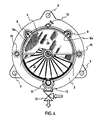
- the rods 9 and the tube 10 are expediently arranged evenly distributed around the circumference of the filter frame 6, as shown in FIG. 4.
- FIG. 1 (B) The other embodiment is shown in FIG. 1 (B) and in FIG. 2 using the example of the right clouding chamber and in FIG. 5.
- the middle support plate 2 and the end walls 14 are in the form of support frames 11 upper circumferential area of the filter frame 6 connected to each other.
- the rods 9 are missing.
- These support frames 11 are approximately quarter-circular in cross-section and fastened on both sides of the upper apex of the filter frame 6 to the central support plate 2 and the end walls 14 and thus cover the cloud chambers in the upper region to a little below the middle, as can be seen clearly from FIG. 5.
- the support frames are plates made of metal, sheet metal or plastic.
- the filter frames 6 are fastened to them in the upper region by means of screw bolts 11 a.
- the filter frames 6 are supported from below by the tube 10 already mentioned.
- the end wall 14 is supported not only by the tube 10 but also by the rods 9 on the outer support frame 2
- the function of the rods 9 in the second embodiment is carried out by a frame 22 which is cage-like or is tubular and connects the end wall 14 to the outer support plate 2 and is screwed to these components.
- the cage frame 22 also supports a bearing for the shaft 8.
- the subdivision of the supporting structure in the slurry chamber into two support frames 11 has the advantage that one of the support frames can be removed during maintenance work and the other then still holds the filter frame.
- each housing jacket 4 is axially displaceable.
- the cylinder 15 is attached to the housing jacket 4, while the piston rod 16 is attached to the outer support plate 2.
- the mounting plate 17 is connected to the right support plate 2 by means of a hydraulic unit, of which the cylinder 19 and the piston rod 20 can be seen in FIG. 2.
- the cylinder 19 is attached to the mounting plate 17, while the piston rod 20 is attached to the right support plate 2.
- the rods 9 can be formed as tubes which have openings 9a in the spaces between the rotor disks 7 and the filter frame, so that they can serve as supply devices for slurry to be filtered, for flushing water, compressed air or the like .
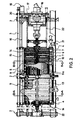
- a turbidity chamber is delimited on the end face on one side by the middle support plate 2 and on the other side by an end wall 14. It is closed to the outside by the essentially tubular housing shell 4, which is guided on the guide rods 3 by means of support eyes 23, in which bores are formed.
- the guide rods 3 can be seen, but it should be emphasized that there are several such guide rods, preferably three guide rods, which are evenly distributed around the filter press.
- the middle support plate 2 and the right end wall 14 each have an annular groove 24 or 25 on their circumference, in which a sealing O-ring 26 is arranged.
- the housing shell 4 has machined sealing surfaces 27 at its ends, which interact with the O-rings 26. From Fig. 3 it can be clearly seen that the O-rings and the sealing surfaces 27 in the open state of the slurry chamber are essentially outside the sphere of influence of the filter chamber.
- the annular grooves 24 and 25 preferably have a dovetail-shaped cross section narrowing towards their free side, and the annular seals 26 each abut their side walls.
- the chamber formed by the ring seal and the side walls and the bottom wall of each ring groove 24 or 25 is provided with a connecting channel 24a or 25a leading to the outside, through which a pressure fluid, in particular compressed air, can be introduced into the chamber.
- a pressure fluid in particular compressed air
- the sealing function is ensured by pressurizing the sealing chambers with compressed air, which brings the sealing rings 26 into contact with the sealing surface of the respective housing shell 4.
- the sealing rings 26 can be inflatable body seals which can be inflated by compressed air or the like.
- each filter unit 5 consists of a filter frame 6 and a rotor disk 7.
- these units are each symmetrical, i.e. each filter frame 6 carries on both sides a filter aid 28, for example in the form of a perforated plate or a cloth, and each rotor disk 7 is provided with pressing surfaces 29 on both sides.
- the filter cake building up between the filter aids 28 and the pressing surfaces 29 is designated by 30 in FIG. 3.
- the filtrate chambers 31 enclosed by the filter media 28 are connected to the tube 10, as shown in the lower area of FIG. 3.
- the rotor disks are hollow. Their interior is connected to the bore of the hollow shaft 8. This will be discussed later.
- the pipe 10 serves mainly as an outlet pipe and is provided with a three-way valve 21 through which the filtrate can be drained, but through which backwashing with a flushing liquid is also possible.
- the tube 10 also penetrates one of the end walls 14 on one side of the filter press, where the three-way valve is shown. If one prefers access to the pipe 10 in the middle support plate 2, that penetration can be dispensed with, so that in the example shown, the right-hand turbidity chamber is designed like the left-hand one.
- FIG. 6 A preferred construction of a rotor disk is shown in FIG. 6. It consists of a hub disk 41, which is fixed in a rotationally fixed manner on the hollow shaft 8, for example by welding or by means of a slot wedge.
- the hub disk 41 carries several guide bushes 42 eccentrically, which extend parallel to the shaft 8 and are welded to the hub disk 42.
- the rotor disk 7 comprises two rigid circular plates 43 which are arranged on both sides of the hub disk 41 and which form the actual pressing surfaces of the rotor disk.
- the plates 43 are axially displaceably guided on the shaft 8 and sealed on the shaft by means of O-ring seals 44, which are seated in corresponding ring grooves in the plates 43.
- the plates 43 are secured against rotation with respect to the shaft by sleeve-shaped guide pins 45, which are inserted into the guide bushes 42 through corresponding bores in the plates 43.
- the two plates 43 of a rotor disk 7 are pulled against one another by tension springs 46.
- the two plates 43 are connected to one another by means of a flexible, ring-shaped seal 47 of essentially U-shaped or n-shaped cross section.
- the outer legs of this seal 47 are attached to the inside of the plates 43.
- the cavity 48 enclosed by the plates 43, the seal 47 and the shaft 8 is connected to the axial bore 50 of the hollow shaft 8 via at least one bore 49 formed in the shaft 8.
- Each of the plates is provided on its outside, which forms the pressing surface, with at least one axially projecting rib 51, which extends from the inner to the outer edge of the plate 43.
- the guide sleeves 45 which hold the plates 43 in a rotationally fixed manner on the guide bush 42 and thus on the hub disk 41, each have a flange ring 52 at their outer end, which is fixed by means of screws 53 to the associated rotor plate 43.
- An O-ring seal 54 in the area of the throat between the flange ring 52 and the cylindrical section 55 of the guide sleeve 45 seals the cavity 48 from the outside.
- the tension spring 46 is arranged within the space enclosed by the sleeves 45 and is fastened on one side by means of a washer 56 and a screw 57 to the flange 52 of the one guide sleeve.
- the spring 46 is fastened by means of such a washer 56, a screw 57 and a nut 58 screwed onto its outwardly projecting end, with the aid of which the tension of the tension spring 46 can also be adjusted.
- the seal 47 has outer legs 47a running on both sides of the U-shaped section approximately parallel to its legs, each of which is tightly clamped between a ring 49 and the inside of the rotor plate 43 by means of screw bolts 60.
- the two plates 43 spread apart in the direction of arrow A, the seal 47 with a U-shaped cross section unfolding in a corresponding manner. If the pressure is released from the cavity 48 again, the tension springs 46 pull the two plates towards each other again until they rest on the end faces of the guide bushes 42.
- Fig. 6 shows an embodiment in which the cavity 48 between the plates 43 was sealed on the shaft side by means of O-rings 44 against the shaft 8
- Fig. 8 shows an embodiment in which the shaft-side sealing is carried out with an arrangement that that of outer peripheral seal 47 is comparable to FIG. 7.
- an elastic sealing ring 61 of U-shaped cross section is arranged between the hub disk 41 and each of the plates 43, which is clamped on the plate 43 by means of an annular disk 62 and screws 63 screwed through the plate 43 and on the hub disk 41 by means of suitable annular ones Disks 64 and screws 63 is clamped.
- Annular beads 65 and corresponding groove-shaped depressions in the disks 64 can facilitate assembly and improve the sealing function.
- Fabric-reinforced rubber or plastic material is advantageously considered as the material for the seals 47 and 61 U-shaped cross-section.
- Such materials with appropriate dimensioning while maintaining high flexibility, can easily withstand the operating pressures, which can be of the order of up to 2 MPa, without suffering any damage.
- the respective choice of material naturally also depends on the type of slurry to be processed, since these seals are directly exposed to the influence of the slurry.
- FIG. 9 shows a rotor disk in a top view.
- a plate 43 can be seen with three evenly distributed guide sleeves 45, the flange rings 52 of which are fastened to the rotor plate 43 with screws 53.
- ribs 51 run in a uniform distribution. These ribs run in an arc shape, so that when the counterclockwise drive is used for the embodiment shown, a conveying movement to the outside is caused by these ribs. In practice, these ribs are about 10 mm high and are sufficient to clear the filter residue from the filter aid on the filter plate.
- the tension springs enclosed by the guide sleeves 45 which cannot be seen in FIG. 9, produce a uniform tension in the arrangement shown when the pressure fluid is released from the cavity of the rotor disk 7, which leads to a return of the plates 43 to their rest position.
- the rotor disk consists of a hub disk which is connected in a rotationally fixed manner to the hollow shaft and which is designed like the hub disk 41 according to FIG. 6.
- the hub disk carries hydraulic or pneumatic piston / cylinder units which are floatingly supported on the hub disk.
- Stiff, circular plates which are comparable to the plates 43 according to FIG. 6, extend on both sides of the hub disk.
- Piston / cylinder units connect the pistons to one plate and the cylinders to the other plate. Since the piston-cylinder units transmit the rotary movement of the hub disc to the plates, they must be designed to be stiff in the direction transverse to their longitudinal extension.
- the plates are connected to one another on their outer circumference by means of a seal which corresponds to the seal 47 according to FIG. 6, but which does not need to have as high a compressive strength as the seal in the embodiment according to FIG. 6, since it is only intended for the purpose Prevent turbidity from entering the space between the panels.
- the plates can have axially extending flange rings on their circumferential edges, which engage with one another and are sealed to one another.
- Double-acting units are advantageously used as piston / cylinder units, in which cylinder chambers lying on both sides of the piston can alternatively be pressurized with a pressure fluid. It is then possible to move the plates away from one another by acting on the one chamber and to bring the plates closer to one another by acting on the other chambers with the pressure fluid.
- two connecting lines have to be laid along the shaft or the actuating fluid has to be reversed into the different cylinder chambers by means of valve mechanisms in the rotor plates.
- the turbidity chambers are closed by moving the housing shells 4 onto the middle support plate 2 of the filter press. Turbidity to be filtered is then continuously introduced into the turbidity chambers through the connections 13. The cloudiness completely fills the cloudiness chambers. Any gaseous or volatile components carried along with the slurry are withdrawn through the openings 12. The filtrate runs through the filter aids 28 into the filtrate chambers behind it and from there into the outlet pipe 10.
- the shaft 8 With the help of the drive 18, the shaft 8 is set into a slow movement during the slurry feed, which can also be reversed if necessary, which keeps the slurry in the slurry chamber in motion, thus preventing the filter aids 28 from clogging prematurely and as the filter cycle progresses a uniform precipitation of the filter residues on the filter aids is ensured.
- the shaft 8 With the help of the hydraulic unit 19, 20, the shaft 8 can be set in a reciprocating movement, preferably with a gradually decreasing amplitude, in order to process the filter residue evenly in accordance with its structure on the filter aid, i.e. knead through.
- filter cake If sufficient filter residue (so-called filter cake) has accumulated on the filter aids, the further supply of turbidity is stopped and the shaft 8 is stopped. A pressure fluid, for example water or hydraulic oil, is then fed via the shaft 8 to the rotor disks 7, which presses the disks 43 apart against the force of the springs 46 and against the filter cake on the filter aids in order to further drain them. The sludge remaining in the filter chamber is then drawn off through the connection 13 and is available for the next filter cycle.
- a pressure fluid for example water or hydraulic oil
- the pressure fluid is then discharged from the rotor disks 7. If desired, compressed air can now be blown into the turbidity chambers through the tubular rods 9 in order to further dry the filter cake.
- the compressed air also pushes the sludge out of the sludge chambers, provided that it has not yet completely drained out of the connections 13. It is avoided that the dry filter cake when cleaning the Trü chamber came into contact with wet components.
- the turbidity chambers are then opened by axially displacing the housing shells 4.
- the space under the filter units 5 is now completely open and the filter cakes can be worked down from the filter aids 28 by rotating the shaft 8 again and by bringing the rotor plates 43 into contact with the filter cakes.
- either the rotor disks 7 can be spread apart in the manner already mentioned above, or the shaft 8 can be moved back and forth with the aid of the hydraulic unit 19, 20.
- backwashing is also possible by supplying a washing liquid to the filter frame 6 from the side of the filtrate chamber 31 in order to clean the filter aids in the backflow. This can be done both when the housing is open and when it is closed.
- the filter cakes can fall freely downwards out of the turbidity chamber when they are being cleaned, without them coming into contact with the seals or sealing surfaces. These sealing surfaces therefore remain clean or require only a minimum of cleaning, which increases both the working speed of the press and the service life of the seals.
Landscapes
- Chemical & Material Sciences (AREA)
- Chemical Kinetics & Catalysis (AREA)
- Engineering & Computer Science (AREA)
- Mechanical Engineering (AREA)
- Physics & Mathematics (AREA)
- Fluid Mechanics (AREA)
- Filtration Of Liquid (AREA)
- Fluid-Pressure Circuits (AREA)
- Dry Shavers And Clippers (AREA)
- Food-Manufacturing Devices (AREA)
- Paper (AREA)
Claims (22)
Applications Claiming Priority (2)
| Application Number | Priority Date | Filing Date | Title |
|---|---|---|---|
| EP85116512 | 1985-12-23 | ||
| EP85116512A EP0226659B1 (fr) | 1985-12-23 | 1985-12-23 | Filtre-presse |
Publications (2)
| Publication Number | Publication Date |
|---|---|
| EP0227084A1 EP0227084A1 (fr) | 1987-07-01 |
| EP0227084B1 true EP0227084B1 (fr) | 1989-05-17 |
Family
ID=8193970
Family Applications (2)
| Application Number | Title | Priority Date | Filing Date |
|---|---|---|---|
| EP85116512A Expired EP0226659B1 (fr) | 1985-12-23 | 1985-12-23 | Filtre-presse |
| EP86117862A Expired EP0227084B1 (fr) | 1985-12-23 | 1986-12-22 | Filtre-presse |
Family Applications Before (1)
| Application Number | Title | Priority Date | Filing Date |
|---|---|---|---|
| EP85116512A Expired EP0226659B1 (fr) | 1985-12-23 | 1985-12-23 | Filtre-presse |
Country Status (6)
| Country | Link |
|---|---|
| EP (2) | EP0226659B1 (fr) |
| AT (1) | ATE43072T1 (fr) |
| DE (1) | DE3570191D1 (fr) |
| ES (1) | ES2008669B3 (fr) |
| GR (1) | GR3000168T3 (fr) |
| ZA (1) | ZA869528B (fr) |
Families Citing this family (12)
| Publication number | Priority date | Publication date | Assignee | Title |
|---|---|---|---|---|
| EP0324865B1 (fr) * | 1988-01-18 | 1993-01-27 | Bauko Baukooperation Gmbh | Presse filtrante |
| ATE94082T1 (de) * | 1988-11-17 | 1993-09-15 | Herco Cff Chiralflow Filter | Druckfilterapparat. |
| DE4005736A1 (de) * | 1990-02-23 | 1991-09-05 | Biersdorf Apparatebau | Rotorfilterpresse mit geteilten filterplatten |
| US5254250A (en) * | 1991-05-30 | 1993-10-19 | Membrex, Inc. | Rotary filtration device and filter pack therefor |
| US5679249A (en) * | 1991-12-24 | 1997-10-21 | Pall Corporation | Dynamic filter system |
| US6117322A (en) * | 1993-06-23 | 2000-09-12 | Pall Corporation | Dynamic filter system |
| US5707517A (en) * | 1995-11-27 | 1998-01-13 | Membrex, Inc. | Immersible rotary disc filtration device |
| US5993674A (en) * | 1998-02-24 | 1999-11-30 | Membrex, Inc. | Rotary disc filtration device with means to reduce axial forces |
| DE59811639D1 (de) | 1998-04-23 | 2004-08-05 | Bauko Baukooperation Gmbh Salz | Anlage zum Abrennen von Feststoffanteilen aus einer Trübe |
| CN108529848B (zh) * | 2018-05-20 | 2020-12-01 | 广州市芦苇环保科技有限责任公司 | 对开型压滤污泥脱水方法 |
| CN115317991A (zh) * | 2022-10-14 | 2022-11-11 | 山东润泽冷链物流有限公司 | 一种海洋海水净化淡化设备的除杂装置 |
| CN115888207A (zh) * | 2022-12-19 | 2023-04-04 | 金锣水务有限公司 | 一种立式压滤机和压滤方法 |
Family Cites Families (4)
| Publication number | Priority date | Publication date | Assignee | Title |
|---|---|---|---|---|
| US2975903A (en) * | 1957-10-31 | 1961-03-21 | Process Filters Inc | Filter |
| US3948776A (en) * | 1974-11-18 | 1976-04-06 | Artisan Industries Inc. | Apparatus and system for generating a protective coating in a rotary concentrator for abrasive solids-containing fluids |
| US4235721A (en) * | 1978-03-16 | 1980-11-25 | Kurita Machinery Manufacturing Company Limited | Reinforcing patch plate applied to liquid passage hole in filter-surfaced expressing sheet on expressing filter plate |
| DE3426527C2 (de) * | 1984-07-18 | 1986-07-24 | Bauko Baukooperation Gmbh, Salzburg | Kammerfilterpresse |
-
1985
- 1985-12-23 DE DE8585116512T patent/DE3570191D1/de not_active Expired
- 1985-12-23 EP EP85116512A patent/EP0226659B1/fr not_active Expired
- 1985-12-23 AT AT85116512T patent/ATE43072T1/de not_active IP Right Cessation
-
1986
- 1986-12-18 ZA ZA869528A patent/ZA869528B/xx unknown
- 1986-12-22 EP EP86117862A patent/EP0227084B1/fr not_active Expired
- 1986-12-22 ES ES86117862T patent/ES2008669B3/es not_active Expired
-
1989
- 1989-09-26 GR GR89400134T patent/GR3000168T3/el unknown
Also Published As
| Publication number | Publication date |
|---|---|
| GR3000168T3 (en) | 1990-12-31 |
| ZA869528B (en) | 1987-08-26 |
| ATE43072T1 (de) | 1989-06-15 |
| DE3570191D1 (en) | 1989-06-22 |
| EP0226659A1 (fr) | 1987-07-01 |
| EP0226659B1 (fr) | 1989-05-17 |
| EP0227084A1 (fr) | 1987-07-01 |
| ES2008669B3 (es) | 1989-08-01 |
Similar Documents
| Publication | Publication Date | Title |
|---|---|---|
| DE60311088T2 (de) | Filterapparat und methode | |
| DE3235552C2 (de) | Rückspülfilter | |
| DE10012186B4 (de) | Filtervorrichtung mit Rückwaschmechanismus | |
| EP0227084B1 (fr) | Filtre-presse | |
| EP0155458A2 (fr) | Plaque de membrane filtrante | |
| DE1761716A1 (de) | Roehren-Filterpresse | |
| DE2521455C2 (de) | Filterpresse | |
| DD252766A5 (de) | Filterpresse | |
| EP0058656B1 (fr) | Dispositif de filtration pour la séparation des matières solides et flottantes des liquides | |
| DE3622103C2 (fr) | ||
| DE4128210C2 (de) | Filter für Flüssigkeiten | |
| DE2322155C2 (de) | Druckdrehfilter | |
| DE3247440C2 (de) | Filterapparat | |
| EP0178389A2 (fr) | Filtre-presse à chambres | |
| DE4017785C2 (fr) | ||
| EP0833685B1 (fr) | Installation de filtration pour la separation de particules de matiere solide | |
| EP1084742A1 (fr) | Dispositif d'alerte en cas de fuite dans des éléments filtrants d'une presse filtrante | |
| DE3411087C2 (fr) | ||
| DE68922851T2 (de) | Filteranordnung zum abtrennen von teilchen aus flüssigkeiten. | |
| AT13455U1 (de) | Dichtung eines Filtratventils für einen Scheibenfilter | |
| DE3138184A1 (de) | Filterapparat | |
| DE19904637C1 (de) | Filterpresse zur Trennung von Suspensionen | |
| DE8817017U1 (de) | Rotor für eine Filterpresse | |
| CH615598A5 (en) | Self-cleaning filter for separating the liquid from suspension | |
| DE2106077C3 (de) | Röhrenfilterpresse |
Legal Events
| Date | Code | Title | Description |
|---|---|---|---|
| PUAI | Public reference made under article 153(3) epc to a published international application that has entered the european phase |
Free format text: ORIGINAL CODE: 0009012 |
|
| AK | Designated contracting states |
Kind code of ref document: A1 Designated state(s): ES GR |
|
| 17P | Request for examination filed |
Effective date: 19870720 |
|
| 17Q | First examination report despatched |
Effective date: 19880420 |
|
| RAP3 | Party data changed (applicant data changed or rights of an application transferred) |
Owner name: BAUKO BAUKOOPERATION GMBH |
|
| GRAA | (expected) grant |
Free format text: ORIGINAL CODE: 0009210 |
|
| AK | Designated contracting states |
Kind code of ref document: B1 Designated state(s): ES GR |
|
| PLBE | No opposition filed within time limit |
Free format text: ORIGINAL CODE: 0009261 |
|
| STAA | Information on the status of an ep patent application or granted ep patent |
Free format text: STATUS: NO OPPOSITION FILED WITHIN TIME LIMIT |
|
| 26N | No opposition filed | ||
| REG | Reference to a national code |
Ref country code: GR Ref legal event code: FG4A Free format text: 3000168 |
|
| PGFP | Annual fee paid to national office [announced via postgrant information from national office to epo] |
Ref country code: GR Payment date: 19971210 Year of fee payment: 12 |
|
| PGFP | Annual fee paid to national office [announced via postgrant information from national office to epo] |
Ref country code: ES Payment date: 19971216 Year of fee payment: 12 |
|
| PG25 | Lapsed in a contracting state [announced via postgrant information from national office to epo] |
Ref country code: ES Free format text: LAPSE BECAUSE OF THE APPLICANT RENOUNCES Effective date: 19981223 |
|
| PG25 | Lapsed in a contracting state [announced via postgrant information from national office to epo] |
Ref country code: GR Free format text: LAPSE BECAUSE OF NON-PAYMENT OF DUE FEES Effective date: 19981231 |
|
| REG | Reference to a national code |
Ref country code: ES Ref legal event code: FD2A Effective date: 20010402 |