EP0227376A2 - Coding boxes - Google Patents
Coding boxes Download PDFInfo
- Publication number
- EP0227376A2 EP0227376A2 EP86309600A EP86309600A EP0227376A2 EP 0227376 A2 EP0227376 A2 EP 0227376A2 EP 86309600 A EP86309600 A EP 86309600A EP 86309600 A EP86309600 A EP 86309600A EP 0227376 A2 EP0227376 A2 EP 0227376A2
- Authority
- EP
- European Patent Office
- Prior art keywords
- frame
- rod
- wheels
- respect
- coding box
- Prior art date
- Legal status (The legal status is an assumption and is not a legal conclusion. Google has not performed a legal analysis and makes no representation as to the accuracy of the status listed.)
- Granted
Links
Images

Classifications
-
- B—PERFORMING OPERATIONS; TRANSPORTING
- B41—PRINTING; LINING MACHINES; TYPEWRITERS; STAMPS
- B41K—STAMPS; STAMPING OR NUMBERING APPARATUS OR DEVICES
- B41K3/00—Apparatus for stamping articles having integral means for supporting the articles to be stamped
- B41K3/02—Apparatus for stamping articles having integral means for supporting the articles to be stamped with stamping surface located above article-supporting surface
- B41K3/04—Apparatus for stamping articles having integral means for supporting the articles to be stamped with stamping surface located above article-supporting surface and movable at right angles to the surface to be stamped
- B41K3/08—Apparatus for stamping articles having integral means for supporting the articles to be stamped with stamping surface located above article-supporting surface and movable at right angles to the surface to be stamped having adjustable type-carrying wheels
Definitions
- the coding box comprises a mild steel frame 12 provided with screw holes (not shown) for fixing in a hot foil printing machine.
- a number of brass print wheels 14 are rotatable about a shaft 16 ( Figure 2b) secured by a screw 17 with respect to the frame 12.
- Each print wheel 14 has a number of outward-facing peripheral flats, which are particularly apparent in Figure 4, bearing indicia, i.e. a digit or letter in mirror image for printing on a package.
Landscapes
- Details Of Rigid Or Semi-Rigid Containers (AREA)
- Auxiliary Devices For And Details Of Packaging Control (AREA)
Abstract
Description
- The invention relates to coding boxes for hot foil printing machines. Such machines are generally used for "use by" dating or stamping other indicia onto packages, particularly to packages containing perishables. The coding box is adjustable to vary the indicia stamped.
- Coding boxes comprise a frame for bolting onto a printing machine. One previously known kind of box comprises also a number of print wheels, each having a number of outward-facing peripheral flats, and each flat bearing an individual digit, letter or character. The print wheels are all rotable about a single axis with respect to the frame, and provided with spring-loaded centring means to ensure that the printing is even. One of the problems is that in operation the vibration eventually tends to wear the mechanism, so that the wheels spin loose and crash, the printing is uneven and the substrate package may be damaged.
- A coding box according to the invention comprises a frame, a number of print wheels rotatable about a shaft with respect to the frame, each print wheel having a number of outward-facing peripheral flats bearing indicia, characterized by each wheel having a through-hole parallel to the shaft and corresponding to each flat, a road passable through the holes for setting the wheels in desired orientations with respect to the frame, and means for locking the rod in a set position.
- A second rod is preferably provided, fast with respect to and parallel to the first rod, and having an enlarged distal end for engagement with a hole in the frame to prevent complete removal of the first rod from the frame. The first and second rods are preferably both fast in a handle by which they may be withdrawn from the wheels to permit rotation of the wheels, and thus variation of the indicia to be stamped. The handle is preferably of heat-resistant material such as PTFE. The locking means may comprise a magnetic part of the handle which is attracted towards the frame (which is generally of ferrous metal). The block is preferably provided with one or more spacers between adjacent print wheels to allow a little flexibility and facilitate the mounting of the wheels in the frame. The wheels and spacers are usually made of brass because of its machinability.
- The first rod passing through the holes in the printing wheels provides positive engagement for aligning the faces on the wheels, and hence ensuring even printing, without the involvement of any spring. The locking means reduces noise from relative movement between parts in use, and hence wear. A coding box according to the invention may be constructed so as to have no removable parts; this makes for safety and reliability.
- The wheels may for example have ten flats each bearing a single digit from 0 to 9. Alternatively, the wheels may have eleven flats so that a blank may be included. Another possibility is for the wheels to have twelve flats and be made wide enough for each flat to bear the name of a month or the whole of an abbreviation therefor.
- The magnet should be heat resistant, and may be small in relation to the other components of the coding box, and may be made to adhere to a part of the handle adjacent the frame. The magnet itself is preferably protected against damage through impact or wear by being mounted in a mild steel cup which itself adheres in a recess to the handle.
-
- Figure 1 is a top view of a coding box according to the invention in a closed or operative position;
- Figure 2 is a side view of the coding box shown in Figure 1;
- Figures 2a, 2b are end views of the coding box as shown in Figure 2;
- Figure 3 is a side view of the coding box shown in Figure 1 in an open or adjustment position;
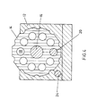
- Figure 4 is a cross-section through a print wheel in the coding box of Figure 1 on a larger scale in the closed position;
- Figures 5, 6 are respectively top and side views of a first modified coding box according to the invention;
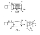
- Figures 7, 8, 8a are top, side and end views respectively of second modified coding box according to the invention; and
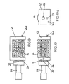
- Figures 9, 10, 10a are similar views of a third modification.
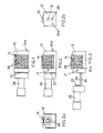
- With reference to the drawings, the coding box comprises a
mild steel frame 12 provided with screw holes (not shown) for fixing in a hot foil printing machine. A number ofbrass print wheels 14 are rotatable about a shaft 16 (Figure 2b) secured by ascrew 17 with respect to theframe 12. Eachprint wheel 14 has a number of outward-facing peripheral flats, which are particularly apparent in Figure 4, bearing indicia, i.e. a digit or letter in mirror image for printing on a package. - Figure 4 also shows how each
print wheel 14 has a number of through-holes 18 parallel to theshaft 16. Eachhole 18 corresponds to one of the peripheral flats on theprint wheel 14. Eachhole 18 as shown has a diameter coincident with a radius of theprint wheel 14 normal to the corresponding flat, but this is not essential as eachhole 18 could be off-set from its corresponding flat by a given amount and still enable the print wheels to be set in desired orientations. A (first)rod 20 is passable through theholes 18 for setting theprint wheels 14 with respect to theframe 12. - A small magnet, which does not itself appear in the drawings adheres inside a
cup 22 which itself adheres in a recess in an end face of ahandle 26 of the coding box. The magnet provides means for locking therod 20 in a set position through its attraction to an end of theshaft 16. - A (second)
rod 24 projects from thehandle 26, and so is fast with respect to thefirst rod 20 to which it is parallel. Therod 24 has an enlargeddistal end 24a for engagement with a hole in theframe 12 to prevent complete removal of thefirst rod 20 from theframe 12. A number ofbrass spacers 28 are provided betweenadjacent print wheels 14. - The coding box is moved from the closed or operative position shown in Figure 1 to the open or adjustment position shown in Figure 3 by pulling the
handle 26 to the left. Therods frame 12 as far as allowed by the engagement between the enlargedend 24a of thesecond rod 24 with a hole in theframe 12 as shown in Figure 3. This leaves theprint wheels 14 free for manual axial rotation to expose faces bearing the desired indicia for printing. A certain amount of slack in theholes 18 around the tip (not shown) of thefirst rod 20 in practice allows therod 20 to be reintroduced into theholes 18 when not perfectly aligned, and in so doing to render the faces co-planar for even printing. When theshaft 16 androds frame 12 and once again take up the operative position shown in Figure 1, thehandle 26 is locked to theframe 12 by the magnet, and the desired indicia are exposed for printing on the top (as shown in Figure 1) of the coding box. - In each modification, the majority of the components are the same, so a single set of reference numerals has been used throughout, and description common to all embodiments is not repeated.
- In the first modified coding box of Figures 5 and 6,
fitters 30 have been screwed to the top faces of theframe 12. Thefitters 30 carry extra information, in Figure 5 No. and A, for printing in every case at either end of the indicia exposed on thewheels 14. Thefitters 30 are of a thickness such as to bring the extra information into the same plane as the indicia exposed on thewheels 14. - In the second modified coding box of Figures 7, 8 and 8a,
fitters 30 marked BEST BEFORE and 26g e extend along the coding box so that the extra information is printed in every case above and below the indicia exposed on thewheels 14. The fitters extend down the outside of the coding box for strength. - The third modification of Figures 9, 10 and 10a has the frame extending along a side of the coding box (the upper side in Figure 9) and not along the base as hitherto. This makes the coining box shallower than in the preceding embodiments which is an advantage in some printing machines. The
wheels 14 in this modification carry indicia showing a sell by date, characters for identification purposes, and a price.
Claims (4)
Applications Claiming Priority (2)
| Application Number | Priority Date | Filing Date | Title |
|---|---|---|---|
| GB8530934 | 1985-12-16 | ||
| GB858530934A GB8530934D0 (en) | 1985-12-16 | 1985-12-16 | Coding boxes |
Publications (3)
| Publication Number | Publication Date |
|---|---|
| EP0227376A2 true EP0227376A2 (en) | 1987-07-01 |
| EP0227376A3 EP0227376A3 (en) | 1988-09-07 |
| EP0227376B1 EP0227376B1 (en) | 1992-09-23 |
Family
ID=10589825
Family Applications (1)
| Application Number | Title | Priority Date | Filing Date |
|---|---|---|---|
| EP86309600A Expired EP0227376B1 (en) | 1985-12-16 | 1986-12-10 | Coding boxes |
Country Status (4)
| Country | Link |
|---|---|
| US (1) | US4719853A (en) |
| EP (1) | EP0227376B1 (en) |
| DE (1) | DE3686809T2 (en) |
| GB (1) | GB8530934D0 (en) |
Families Citing this family (10)
| Publication number | Priority date | Publication date | Assignee | Title |
|---|---|---|---|---|
| US4967654A (en) * | 1989-07-10 | 1990-11-06 | Amp Incorporated | Print head setting apparatus |
| DE4403058C1 (en) * | 1994-02-02 | 1995-02-02 | Eoc Normalien Gmbh & Co Kg | Marking insert for an injection mould |
| GB0309616D0 (en) | 2003-04-28 | 2003-06-04 | Angiomed Gmbh & Co | Loading and delivery of self-expanding stents |
| GB0810749D0 (en) | 2008-06-11 | 2008-07-16 | Angiomed Ag | Catherter delivery device |
| US9750625B2 (en) | 2008-06-11 | 2017-09-05 | C.R. Bard, Inc. | Catheter delivery device |
| AU323511S (en) * | 2008-10-17 | 2009-01-09 | A R C Strang Australia Pty Ltd | Wheel spacer |
| GB0901496D0 (en) | 2009-01-29 | 2009-03-11 | Angiomed Ag | Delivery device for delivering a stent device |
| GB0909319D0 (en) | 2009-05-29 | 2009-07-15 | Angiomed Ag | Transluminal delivery system |
| CN106079938B (en) * | 2016-06-20 | 2018-08-17 | 苏州全新机械配件有限公司 | A kind of Simple rotating stamp device |
| CN107791704A (en) * | 2017-11-06 | 2018-03-13 | 于浩 | A kind of forging heat makes the adjustable grinding tool of steel seal |
Family Cites Families (12)
| Publication number | Priority date | Publication date | Assignee | Title |
|---|---|---|---|---|
| US18249A (en) * | 1857-09-22 | robertson | ||
| FR339437A (en) * | 1903-01-12 | 1904-06-09 | Frederic De Coppet | Articulated stamper |
| US848887A (en) * | 1904-07-08 | 1907-04-02 | James Thomas Earle | Automatic identification-stamp. |
| US988242A (en) * | 1909-07-22 | 1911-03-28 | Joseph Blitz | Dating-stamp. |
| FR497756A (en) * | 1913-12-12 | 1919-12-17 | Frederic De Coppet | Articulated stamp |
| US1289539A (en) * | 1918-04-08 | 1918-12-31 | Timoty B Powers | Multiple-stamp device. |
| US1446013A (en) * | 1921-11-02 | 1923-02-20 | Joseph L Lawrence | Ticket dater |
| FR673790A (en) * | 1929-02-23 | 1930-01-20 | Spring-loaded date stamps | |
| US2506729A (en) * | 1947-11-29 | 1950-05-09 | P M Stamping Device Company Lt | Stamping device |
| US3916783A (en) * | 1972-09-13 | 1975-11-04 | Texmark Inc | Automatic sequential textile marking machine |
| US4228736A (en) * | 1978-07-28 | 1980-10-21 | Griffiths John B | Printing apparatus |
| US4453468A (en) * | 1982-12-29 | 1984-06-12 | Shenoha James L | Heat conducting magnetic type holder for imprinters |
-
1985
- 1985-12-16 GB GB858530934A patent/GB8530934D0/en active Pending
-
1986
- 1986-12-08 US US06/938,972 patent/US4719853A/en not_active Expired - Fee Related
- 1986-12-10 EP EP86309600A patent/EP0227376B1/en not_active Expired
- 1986-12-10 DE DE8686309600T patent/DE3686809T2/en not_active Expired - Fee Related
Also Published As
| Publication number | Publication date |
|---|---|
| EP0227376B1 (en) | 1992-09-23 |
| EP0227376A3 (en) | 1988-09-07 |
| US4719853A (en) | 1988-01-19 |
| GB8530934D0 (en) | 1986-01-29 |
| DE3686809T2 (en) | 1993-02-25 |
| DE3686809D1 (en) | 1992-10-29 |
Similar Documents
| Publication | Publication Date | Title |
|---|---|---|
| US4719853A (en) | Coding box with selectively adjustable printing wheels | |
| DE69707138T2 (en) | RIBBON CASSETTE CONTAINER FOR THERMAL TRANSFER PRESSURE | |
| EP0581056A1 (en) | Identification device for flexible cylinder coverings | |
| DE19742456C2 (en) | Procedure for marking housings | |
| US4628815A (en) | Reversible lockup system for magnetically securable printing plates | |
| EP0221555B1 (en) | Postage meter cover assembly | |
| EP0221557A2 (en) | Modular universal postage meter | |
| DE2932426C2 (en) | Device for an election printing roller | |
| GB2243580A (en) | Verifying print position setting of marking elements | |
| US4431911A (en) | Cash replacement system including an encoded card and card acceptor | |
| US5005477A (en) | Double truck printing registration system for a rotary printing press | |
| EP0221556B1 (en) | Postage meter stepper motor module | |
| DE3400888A1 (en) | PRINT PIN OPERATING DEVICE FOR DOT MATRIX PRINTER AND METHOD FOR THEIR PRODUCTION | |
| US4656341A (en) | Postage meter printhead assembly | |
| US4852478A (en) | Apparatus for imprinting a document with secure, machine readable information | |
| US4389564A (en) | Indexing mechanism for card acceptor | |
| DE69403870T2 (en) | Printing plate cassette for a franking machine | |
| US6408752B1 (en) | Mounting printing plate cylinder to rotatable drive shaft | |
| US4726215A (en) | Adjustable diameter stamp | |
| US24341A (en) | Method of priwtietg bank-notes | |
| DE3883967D1 (en) | Device for printing endorsements on documents. | |
| US4777353A (en) | Value wheel rod lock | |
| JP3063208U (en) | Metal tag | |
| SU743281A1 (en) | Mosaic pressing head | |
| US4810114A (en) | Print wheel with self-contained means for print wheel alignment |
Legal Events
| Date | Code | Title | Description |
|---|---|---|---|
| PUAI | Public reference made under article 153(3) epc to a published international application that has entered the european phase |
Free format text: ORIGINAL CODE: 0009012 |
|
| AK | Designated contracting states |
Kind code of ref document: A2 Designated state(s): DE FR GB NL |
|
| PUAL | Search report despatched |
Free format text: ORIGINAL CODE: 0009013 |
|
| AK | Designated contracting states |
Kind code of ref document: A3 Designated state(s): DE FR GB NL |
|
| 17P | Request for examination filed |
Effective date: 19880825 |
|
| 17Q | First examination report despatched |
Effective date: 19891201 |
|
| GRAA | (expected) grant |
Free format text: ORIGINAL CODE: 0009210 |
|
| AK | Designated contracting states |
Kind code of ref document: B1 Designated state(s): DE FR GB NL |
|
| REF | Corresponds to: |
Ref document number: 3686809 Country of ref document: DE Date of ref document: 19921029 |
|
| ET | Fr: translation filed | ||
| PLBE | No opposition filed within time limit |
Free format text: ORIGINAL CODE: 0009261 |
|
| STAA | Information on the status of an ep patent application or granted ep patent |
Free format text: STATUS: NO OPPOSITION FILED WITHIN TIME LIMIT |
|
| 26N | No opposition filed | ||
| PGFP | Annual fee paid to national office [announced via postgrant information from national office to epo] |
Ref country code: FR Payment date: 19941213 Year of fee payment: 9 Ref country code: DE Payment date: 19941213 Year of fee payment: 9 |
|
| PGFP | Annual fee paid to national office [announced via postgrant information from national office to epo] |
Ref country code: NL Payment date: 19941231 Year of fee payment: 9 |
|
| PG25 | Lapsed in a contracting state [announced via postgrant information from national office to epo] |
Ref country code: NL Effective date: 19960701 |
|
| PG25 | Lapsed in a contracting state [announced via postgrant information from national office to epo] |
Ref country code: FR Effective date: 19960830 |
|
| NLV4 | Nl: lapsed or anulled due to non-payment of the annual fee |
Effective date: 19960701 |
|
| PG25 | Lapsed in a contracting state [announced via postgrant information from national office to epo] |
Ref country code: DE Effective date: 19960903 |
|
| REG | Reference to a national code |
Ref country code: FR Ref legal event code: ST |
|
| REG | Reference to a national code |
Ref country code: GB Ref legal event code: IF02 |
|
| PGFP | Annual fee paid to national office [announced via postgrant information from national office to epo] |
Ref country code: GB Payment date: 20041230 Year of fee payment: 19 |
|
| APAH | Appeal reference modified |
Free format text: ORIGINAL CODE: EPIDOSCREFNO |
|
| PG25 | Lapsed in a contracting state [announced via postgrant information from national office to epo] |
Ref country code: GB Free format text: LAPSE BECAUSE OF NON-PAYMENT OF DUE FEES Effective date: 20051210 |
|
| GBPC | Gb: european patent ceased through non-payment of renewal fee |
Effective date: 20051210 |