EP0229662B1 - Appareil de microscopie chirurgicale - Google Patents
Appareil de microscopie chirurgicale Download PDFInfo
- Publication number
- EP0229662B1 EP0229662B1 EP87100356A EP87100356A EP0229662B1 EP 0229662 B1 EP0229662 B1 EP 0229662B1 EP 87100356 A EP87100356 A EP 87100356A EP 87100356 A EP87100356 A EP 87100356A EP 0229662 B1 EP0229662 B1 EP 0229662B1
- Authority
- EP
- European Patent Office
- Prior art keywords
- cornea
- index
- surgical microscope
- optical system
- microscope
- Prior art date
- Legal status (The legal status is an assumption and is not a legal conclusion. Google has not performed a legal analysis and makes no representation as to the accuracy of the status listed.)
- Expired - Lifetime
Links
- 210000004087 cornea Anatomy 0.000 claims description 94
- 230000003287 optical effect Effects 0.000 claims description 71
- 238000005286 illumination Methods 0.000 claims description 15
- 230000004044 response Effects 0.000 claims description 4
- 238000001356 surgical procedure Methods 0.000 claims description 3
- 238000005259 measurement Methods 0.000 description 17
- 238000010586 diagram Methods 0.000 description 8
- 201000009310 astigmatism Diseases 0.000 description 7
- 239000012141 concentrate Substances 0.000 description 3
- 0 *=*C1C(CC2)C2CCC1 Chemical compound *=*C1C(CC2)C2CCC1 0.000 description 2
- 230000008859 change Effects 0.000 description 2
- 230000000694 effects Effects 0.000 description 2
- 201000000766 irregular astigmatism Diseases 0.000 description 2
- 238000002406 microsurgery Methods 0.000 description 2
- 230000004048 modification Effects 0.000 description 2
- 238000012986 modification Methods 0.000 description 2
- 230000035945 sensitivity Effects 0.000 description 2
- 238000004804 winding Methods 0.000 description 2
- 230000009471 action Effects 0.000 description 1
- 238000001444 catalytic combustion detection Methods 0.000 description 1
- 238000002316 cosmetic surgery Methods 0.000 description 1
- 238000001514 detection method Methods 0.000 description 1
- 229910052736 halogen Inorganic materials 0.000 description 1
- 150000002367 halogens Chemical class 0.000 description 1
- 238000007689 inspection Methods 0.000 description 1
- 230000001788 irregular Effects 0.000 description 1
- 201000009308 regular astigmatism Diseases 0.000 description 1
- 230000000717 retained effect Effects 0.000 description 1
Images


Classifications
-
- A—HUMAN NECESSITIES
- A61—MEDICAL OR VETERINARY SCIENCE; HYGIENE
- A61F—FILTERS IMPLANTABLE INTO BLOOD VESSELS; PROSTHESES; DEVICES PROVIDING PATENCY TO, OR PREVENTING COLLAPSING OF, TUBULAR STRUCTURES OF THE BODY, e.g. STENTS; ORTHOPAEDIC, NURSING OR CONTRACEPTIVE DEVICES; FOMENTATION; TREATMENT OR PROTECTION OF EYES OR EARS; BANDAGES, DRESSINGS OR ABSORBENT PADS; FIRST-AID KITS
- A61F9/00—Methods or devices for treatment of the eyes; Devices for putting in contact-lenses; Devices to correct squinting; Apparatus to guide the blind; Protective devices for the eyes, carried on the body or in the hand
- A61F9/007—Methods or devices for eye surgery
- A61F9/013—Instruments for compensation of ocular refraction ; Instruments for use in cornea removal, for reshaping or performing incisions in the cornea
-
- G—PHYSICS
- G02—OPTICS
- G02B—OPTICAL ELEMENTS, SYSTEMS OR APPARATUS
- G02B21/00—Microscopes
- G02B21/0004—Microscopes specially adapted for specific applications
- G02B21/0012—Surgical microscopes
-
- A—HUMAN NECESSITIES
- A61—MEDICAL OR VETERINARY SCIENCE; HYGIENE
- A61B—DIAGNOSIS; SURGERY; IDENTIFICATION
- A61B90/00—Instruments, implements or accessories specially adapted for surgery or diagnosis and not covered by any of the groups A61B1/00 - A61B50/00, e.g. for luxation treatment or for protecting wound edges
- A61B90/20—Surgical microscopes characterised by non-optical aspects
Definitions
- the present invention relates to a surgical microscope system, and more particularly, to a surgical microscope system for performing a microscopic surgical operation.
- microsurgery of performing a microscopic surgical operation while observing with a microscope is widely used in public.
- the so-called microsurgery which makes it possible to perform a high precision microscopic surgical operation, has greatly contributed to the wide fields including the ophthalmology, neurosurgery, otorhinolaryngology, plastic surgery and the like.
- ophthalmology for performing a cornea operation by measuring a radius of curvature of the cornea and controlling the extent of a suturing operation in accordance with the measured value so as to prevent the corneal astigmatism from occurring after the operation.
- Japanese Laid-Open Publication Sho 59/1984 - 155232 discloses an apparatus for measuring the cornea configuration which is mounted on a surgical microscope in a unitary manner therewith. The apparatus will be described hereinafter with reference to Figs. 1 to 4.
- a surgical microscope includes a body 1, an objective lens 2, a light source 3 such as a circular fluorescent lamp for illuminating a projection index 4.
- a reflected image 4 ⁇ (virtual image) of the cornea Ec is formed to the index 4 by the convex-mirror action of the cornea Ec.
- the reflected image 4 ⁇ varies in its size in accordance with a curvature of the radius of the cornea Ec.
- the cornea Ec has regular astigmatism
- the reflectd image 4 ⁇ is in an elliptic form and when the cornea Ec has irregular astigmatism, the reflected image 4 ⁇ is in an irregular form. For this reason, it is possible to determine a surface configuration of the cornea Ec by measuring the reflected image 4 ⁇ thereof.
- An optical path change member 5 is provided in an optical system for measuring a cornea configuration which has a reflecting surface oblique to the exterior of of an observation optical system in a space between the binocular observation optical paths.
- the optical path change member 5 is fixed adjacent to the objective lens 2 to the microscope body 1.
- Reference numeral 6 is an objective lens of the cornea configuration measuring optical system.
- a diaphragm plate 7 is disposed adjacent to the rear side focus of the objective lens 6.
- a deflecting prism 8 is fixed adjacent to the rear side of the diaphragm plate 7.
- the diaphram plate 7 has, for example, five small through-holes at its center portion, as shown in Fig. 2.
- the deflecting prism 8 is in such a form as five prism pieces of the wedge type are put together in a unitary form, as shown in Fig. 3.
- the through-hole openings of the diaphragm plate 7 agree with the respective centers of the prism pieces of the deflecting prism 8.
- Projecting light beams from the reflected image 4 ⁇ incident upon the objective lens 6 are divided into five beams through the openings of the diaphragm plate 7 and the deflecting prism 8.
- the five beams are then reflected by a reflecting mirror 9 to form images respectively upon light receiving surfaces of detector elements 10, such as one dimensional photodiode array.
- detector elements 10 are arranged respectively at positions where projected images 4 ⁇ are formed to the reflected image 4 ⁇ , for example, as shown in Fig. 4.
- a measuring switch (not shown) is turned on and at the same time a configuration of the reflected image 4 ⁇ is detected by the detector elements 10.
- the detected signals are electrically amplified and calculated by a signal operating circuit (not shown) to determine the major and minor axes of an ellipse and the elliptic axes for the reflected image 4'. From these data the radius of curvature, the degree of astigmatism, the axial angle of astigmatism and the like are determined and displayed.
- the cornea reflected image is not circular or elliptic because of irregular astigmatism, radii of curvature are determined and displayed respectively for meridional directions of the cornea.
- the surgical microscope comprises an illumination light source for observation and/or measuring the configuration of the cornea of an eye and possibly photographing, the index projecting optical system including an index which is removably inserted into the trajectory of the illumination light beam emitted from the illumination light source and emerging from an objective lens of the observation optical system, thereby dispensing with a particular light source and its switch for measuring the cornea configuration and securing an operation space with a simple operation except during the measurement.
- a perforated index which is illuminated by a light source for photographing of the surgery microscope is insertably disposed in the microscope optical path between the objective lens and an eye to be measured and a detector is provided for detecting whether the perforated index lies with the microscope optical path, whereby a cornea configuration measuring mode and a photographing mode are automatically switched with an output from the detector when the perforated index lies within the microscope optical path or not, respectively, thus allowing an operator to concentrate his attention on an operation.
- the cornea configuration can be measured with a light source for photographing and its switching operation, any particular light source and its switch for measuring the cornea configuration can be dispensed with, so that it is possible to provide an inexpensive surgery microscope which is improved in operation and has a compact and simple structure.
- an illumination during the cornea configuration measurement is given by a bright light source for an electronic flashlight emission, it is possible to momentarily perform the measurement even with a photosensitive element of low sensitivity.
- the cornea configuration measuring and the photographing modes can be automatically switched by detecting whether the index exists or not and in order to develop a trigger signal only a single switch, for example, may be arranged at a proximal portion, so that it is still possible to easily operate and to allow an operator to concentrate his attention on the operation. Upon completion of the cornea configuration measurement, it is possible to simply remove the index so as to make a surgical operation safe and reliable.
- Fig. 5 which illustrates an optical system of a first embodiment of the present invention
- E designates an eye to be measured
- C designates a cornea of the eye E.
- An illumination light source 11 such as a halogen lamp illuminates the eye E through an objective lens 13 by light beams reflected by a prism 12 and thus forms the so-called coaxial illumination optical system of a surgical microscope.
- the objective lens 13, a relay lens 14 and an eyepiece 15 form an observation optical system of the surgical microscope.
- pairs of the relay lens 14 and the eyepiece 15 are disposed in symmetry with respect to the optical axis O of the objective lens 13 in a plane perpendicular to the drawing sheet so as to stereoscopically observe the eye E with right and left eyes of an observer.
- the slit plate 16 has a central opening 16a, as shown in Fig. 6, viewed from the direction of the optical axis of the surgical microscope and further includes shade plates 16b, 16b ⁇ around the periphery of the hole 16a.
- An annular belt-shaped slit 16c is provided between the shade plates 16b, 16b ⁇ . Light beams passing through the slit 16c impinge upon the cornea C of the eye E after passed through a collimator lens 17.
- the collimator lens 17 forms a cylindrical lens which has the refractive power in each of meridian surfaces and has no refractive power in a surface perpendicular to each of the meridian surface, that is, a surface including a ring-shaped circumference.
- the collimator lens 17 is disposed at a distance of its focal length from the slit 16c, which makes light rays appeared from the slit 16c parallel so as to project the light rays from the optically infinite point onto the cornea C.
- Light rays appeared from the slit 16c have the same angle ⁇ around the optical axis O.
- a virtual image 16 ⁇ of the annular slit 16c is formed on the cornea C by mirror reflection.
- the slit plate 16 and the collimator lens 17 are attached to a microscope body 27, as shown in Fig. 7, which are integrally supported by a slide arm 20 fixed into a guide 19 provided on the microscope body 27.
- the slide arm 20 is insertable at a pre-determined position in such a manner that it is rotatable around an axis parallel to the optical axis of the microscope and is movable up and down in the direction of the optical axis.
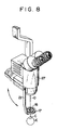
- Figs. 8 and 9 show modifications of a structure including the perforated slit plate 16 and the collimator lens 17.
- the slit plate 16 and the collimator lens 17 are supported by a rotary arm 21 and a magnet arm or support member 22 to secure to the microscope body 27.
- the slit plate 16 and the collimator lens 17 are insertable in a predetermined position on the optical axis O of the microscope by turning the support member 21.
- the slit plate 16 and the collimator lens 17 are insertable in a predetermined position on the optical axis O of the microscope by attaching the support member 22 to the microscope body 27 utilizing the magnetic force of a magnet portion 22a of the support member 22, resulting in a simple operation.
- the cornea configuration measuring optical system will now be described hereinafter.
- the virtual image 16c ⁇ of the slit 16c which is formed on the cornea C of the eye E is transmitted through the collimator lens 17, the central opening 16a of the slit plate 16, the objective lens 13 and an interference filter 18 such as a dichroic mirror which transmits visible rays and reflects infrared rays.
- reflected infrared rays pass through a relay lens system 19 and further are transmitted through or reflected by half mirrors 20a, 20b and finally are formed in an image on three pieces of one-dimensional sensors 21a, 21b and 21c, such as CCDs which are sensitive to infrared rays.
- the sensors 21a, 21b, 21c as viewed from the direction of the optical axis O ⁇ are arranged, as shown in Fig. 10, so as to be angularly displaced with respect to each other by 120°.
- the cornea C is generally regarded as a toric plane, even though the annular slit 16c is in a true circle, the virtual image 16c ⁇ on the cornea C and images 16c ⁇ on the sensors 21a, 21b, 21c take a form of ellipse. Consequently, the radius of curvature r, the degree of astigmatism and the astigmatic axial angle A of the cornea C can be determined by measuring the elliptic configuration.
- ax2 + by2 + 2cxy + dx + ey + 1 0
- a to e are five unknown quantities, which can be determined by taking coordinates to five points out of six on the image formed on the three one-dimensional sensors 21a, 21b, 21c.
- the optical axis of the eye E to be measured is aligned with the optical axis O of the microscope and a distance between the objective lens 13 and the cornea C of the eye E is adjusted by effecting a focusing operation with the microscope body 27 moving vertically together with the objective lens 13.
- the cornea configuration is measured by interposing the slit plate 16 and the collimator lens 17 of the index projecting optical system at a predetermined position on the optical axis O between the objective lens 13 and the cornea C.
- a binocular stereoscopic microscope has a large depth of focus and it is difficult to adjust a distance between the objective lens 13 and the cornea C of the eye E. Accordingly, while there may be some variations in the distance between the cornea C and the slit plate 16 and the collimator lens 17, such variations do not practically affect a measuring accuracy since an image of the slit 16c is projected onto the cornea C with parallel light rays.
- the slit plate 16 and the collimator lens 17 are immediately removed from the optical axis O so as not to interrupt a surgical operation to secure an operational space, resulting in a smooth and safe surgical operation.
- Fig. 11 shows an optical system of a second embodiment of a surgical microscope according to the present invention.
- Like reference numerals designate like or corresponding parts and hence their descriptions will be omited.
- the illumination light source 11 for observation, relay lens 24, flashlight emission source 23 for photographing, prism 12 and objective lens 13 constitute the so-called coaxial illumination optical system of the surgical microscope.
- the objective lens 13, relay lens 14 and eyepiece 15 constitute the observation optical system.
- the light source 11, prism 12, objective lens 13, perforated slit plate 16 and collimator lens 17 constitute the index projecting optical system.
- the flashlight emission source 23, prism 12, objective lens 13, perforated slit plate 16, collimator lens 17, dichroic mirror 18, relay lens system 19, half mirrors 20a, 20b and one-dimensional sensors 21a, 21b, 21c constitute the cornea configuration measuring optical system.
- the flashlight emission source 23, prism 12, objective lens 13, dichroic mirror 18, relay lens 14, beam splitter 25, image forming lens 26 and camera 57 constitute the photographing optical system.
- the eyepieces 15 constitute a pair of optical system together with the relay lenses 14 in symmetry with respect to the optical axis O of the objective lens 13 on the plane perpendicular to the drawing sheet.
- Both perforated slit plate 16 and the collimator lens 17 is removably attached to the microscope body 27 by means of the support member 22, as shown in Fig. 9.
- the magnet portion 22a of the magnet arm is insertable in the recess 27b formed in the side wall of the microscope body 27.
- the tip end of a movable contact piece 50a of a microswitch 50 is sticking out of the recess 27b, which is used as an index detector provided in the side wall of the microscope body 27 which will be described later.
- reference numerals 50 designates the above-mentioned index detector.
- a changeover device 51 includes a main switch (not shown) for turning a flashlight emission control on and off by selecting either of a cornea measuring control 55 and a camera control 56 which will be described later, in response to an output from the index detector 50.
- a portion I enclosed with a dotted line forms the cornea configuration measuring system which includes an index image detector 52 for detecting an index image by cornea reflection, a calculator 53 for calculating parameters of a cornea configuration, a cornea measuring indicator 54 and the above-mentioned cornea measuring control 55 for controlling the index image detector 52, calculator 53 and cornea measuring indicator 54.
- a portion II enclosed with a dotted line forms the photographing system which includes a camera 57, a film winder 58 and the above-mentioned camera control 56 for controlling the camera 57 and the winder 58 which are constituted so as to deliver a signal for indicating shutter opening conditions.
- a flashlight emission control 60 for controlling a flashlight power source 61 and a flashlight emission tube 62 and a trigger signal generating means 63 such as a foot switch and the like.
- the support member 22 When a cornea configuration is measured, the support member 22 is first mounted at a predetermined position of the microscope body 27. The cornea configuration is measured by light rays from the flashlight emission source 21 in the same manner as described in the first embodiment. At this time, when the perforated slit plate 16 and the collimator lens 17 are inserted in the optical path by mounting the support member 22 on the microscope body 27, the contact piece 50a of the index detector 50 is pushed by the magnet portion 22a to produce a detection signal which is fed to the changeover device 51. The changeover device 51 selects one of the cornea configuration measuring control 55 and the camera control 56 in response to the signal from the image detector 50 and maintains the selected control on standby.
- a main switch within the device also turns on to maintain the flashlight emission control 60 on standby. Consequently, the condition that a series of operations will be commenced by a trigger signal input from a trigger signal generating means 63 is caused. Consequently, assuming that the cornea configuration measuring control 55 is selected in the changeover device 51 by an output from the index detector 50 to be in the cornea configuration measuring mode, when a trigger signal is given from the trigger signal generating means 63 to the changeover device 51, it delivers the trigger signal to both the cornea configuration measuring control 55 and the flashlight emission control 60. Then, the cornea configuration measuring device 55 is ready for receiving an output from the index image detector 52. At the same time, the flashlight emission control 60 causes the flashlight emission tube 62 to emit flashlight by receiving the trigger signal.
- a light amount detector within the flashlight emission control 60 commences the photometric operation simultaneously with the commencement of flashlight emission.
- the emission control 60 causes the tube 62 terminate the flashlight emission and delivers a flashlight emission terminate signal to the cornea configuration measuring control 55.
- the index image detector 52 delivers an output corresponding to a configuration of an index image which is obtained by reflection of the cornea C of the eye E to the cornea configuration measuring control 55.
- the control 55 temporarily retains the output signal and inhibits an input from the index image detector 52 until the flashlight emission terminate signal from the emission control 60 is inputted to feed the retained data of the index image to the calculator 53.
- the calculator 3 calculates parameters of the cornea configuration using the quadratic equation described above to feed an output through the control 55 to the cornea configuration measuring indicator 54 which displays the calculated results.
- the control 55 is directly connected to an exterior apparatus such as a personal computer or the like the calculator 53 is not required.
- the cornea configuration can be measured by a series of operations described above.
- the support member 22 is removed from the microscope body 27 to eliminate both the slit plate 16 and the collimator lens 17 from the optical path.
- the eye E and the cornea C are illuminated through the prism 12 and the objective lens 13 by allowing the flashlight emission source 23 to emit flashlight, light rays from the cornea C is transmitted through the objective lens 13 to the dichroic mirror 18 in which only visible rays are transmitted. Part of the transmitted rays are reflected by the beam splitter 25 to take a photograph of the cornea C by the camera 57 through the image forming lens 26.
- the camera control 56 detects whether the film winding operation of the camera 57 is completed. When not completed, the camera control 56 causes the film winder 58 to operate. After the completion of the film winding, when the changeover device 51 receives a trigger signal from the trigger signal generating means 63, the device 51 transmits the trigger signal to the camera control 56. Then, the camera control 56 causes the camer 57 to release a shutter. When the shutter is fully opened, the camera 57 delivers a flashlight emission initiate signal to the flashlight emission control 60. Then, a flashlight emission and a photometric operation are performed in the same manner as in the cornea configuration measurement. When the shutter is closed, the camera control 56 receives photographing completion signal from the camera 57 to operate the film winder, whereby a film is wound. Thus, the photographing is performed by the above-mentioned series of operations.
- the support member 22 for supporting the slit plate 16 and the collimator lens 17 is easily and promptly detachable to the microscope body 27 except during the cornea configuration measurement, so as not to be hindrance to a surgical operation.
- the cornea configuration measuring mode and the photographing mode are automatically switched depending upon whether the support member 22 is in the optical axis in response to an output from the index detector 50.
- the recess 27b of the microscope body 27 in which the support member 22 is inserted is positioned at a predetermined distance, a relative distance between the slit plate 16 and the collimator lens 17 and the eye E under inspection is determined by a working distance of the objective lens when the microscope is brought into focus on the cornea while viewing through the microscope.
- the changeover device 51, the cornea configuration measuring control 55, the calculator 53 and the camera control 56 are separately provided, it will be easily understood that the controlling and the calculating operations may be achieved using a computer with software of the same functional structure.
- the index detector 50 is constituted by a microswitch, it is further understood that the detector 50 is not limited thereto but may be a photo-interrupter or the like which is disposed so as to be interrupted by the support member 22 when the slit plate 16 and the collimator lens 17 are within the optical path.
- the cornea configuration can be measured with the light source for photographing and its switch operation, no particular light source for cornea configuration measurement and its switch is required, so that it is possible to provide a compact and inexpensive surgical microscope of a simple structure and of an easy handling.
- the illumination during the cornea configuration measurement is performed with a bright flashlight emission source, it is possible to use even a photosensitive element of low sensitivity and to effect the measurement momentarily.
- the index upon completion of the cornea configuration measurement the index can be easily removed, so that the ease and safety of operation are improved.
- Fig. 14 shows another optical system utilizing a flashlight source for photographing which is housed within a surgical microscope as an illumination light source for the cornea configuration measurement according to a third embodiment of the present invention.
- the system causes the flashlight source 23 to emit light rays in synchronism with the time of the measurement and has advantages of obtaining a sufficient amount of measuring light and a high-speed measurement.
Landscapes
- Health & Medical Sciences (AREA)
- Physics & Mathematics (AREA)
- General Health & Medical Sciences (AREA)
- Surgery (AREA)
- Ophthalmology & Optometry (AREA)
- Engineering & Computer Science (AREA)
- Heart & Thoracic Surgery (AREA)
- Optics & Photonics (AREA)
- Nuclear Medicine, Radiotherapy & Molecular Imaging (AREA)
- Analytical Chemistry (AREA)
- Chemical & Material Sciences (AREA)
- Biomedical Technology (AREA)
- General Physics & Mathematics (AREA)
- Vascular Medicine (AREA)
- Life Sciences & Earth Sciences (AREA)
- Animal Behavior & Ethology (AREA)
- Public Health (AREA)
- Veterinary Medicine (AREA)
- Eye Examination Apparatus (AREA)
- Microscoopes, Condenser (AREA)
Claims (17)
- Système microscopique chirurgical pour la chirurgie des yeux, comportant un système optique d'observation (13, 14, 15) pour l'observation de la cornée (C) d'un oeil (E), une source de lumière d'illumination (11) pour l'illumination de la cornée, et un système optique de projection de repère, associé à un système de mesure de la configuration cornéenne (18, 19, 20, 21),
caractérisé en ce que
ledit système optique de projection de repère comprend un repère (16) qui peut être mis en place, de façon séparable, dans la trajectoire du rayon lumineux d'illumination émis par ladite source de lumière d'illumination et émergeant de la lentille d'objectif (13) du système optique d'observation en direction de la cornée (C). - Système microscopique chirurgical selon la revendication 1, caractérisé en ce que
ledit repère (16) dudit système optique de projection de repère est attaché à un élément de support (20, 21, 22) qui est monté, de façon séparable, sur le corps (27) du microscope dans une position prédéterminée par rapport à l'axe optique (O) du microscope. - Système microscopique chirurgical selon la revendication 2, caractérisé en ce que
ledit élément de support (20) est attaché à un élément de guidage (19) prévu sur le corps (27) du microscope, ledit élément de support pivotant autour d'un axe parallèle à l'axe optique du microscope, et pouvant être glissé verticalement dans la direction dudit axe optique. - Système microscopique chirurgical selon la revendication 2, caractérisé en ce que
ledit élément de support (21) est monté à pivotement sur le corps (27) du microscope, de manière à prendre une position prédéterminée soit dans l'axe optique (O) du microscope soit en-dehors de celui-ci. - Système microscopique chirurgical selon la revendication 2, caractérisé en ce que
ledit élément de support (22) est muni d'une section d'aimant (22a) afin de pouvoir être attaché, de façon amovible, au microscope (27) dans une position prédéterminée de celui-ci, telle que le repère (16) se trouve dans l'axe optique du microscope. - Système microscopique chirurgical selon l'une quelconque des revendications 1 à 5, caractérisé en ce que
ledit repère (16) dudit système optique de projection de repère comporte un disque à fente perforé (16), fait d'un disque d'écran, son ouverture centrale (16a) présentant une fente annulaire (16c) en forme de bande, située à la périphérie de l'ouverture. - Système microscopique chirurgical selon la revendication 6, caractérisé en ce que
au moment de la mesure de la configuration de la cornée, ladite ouverture centrale (16a) dudit disque à fente (16) permet le passage à travers elle de l'image de la fente annulaire (16c) en forme de bande que réfléchit la cornée de l'oeil à mesurer. - Système microscopique chirurgical selon l'une quelconque des revendications 1 à 7, caractérisé en ce que
ledit système optique de projection de repère comprend une lentille collimatrice (17) disposée en aval du repère (16). - Système microscopique chirurgical selon la revendication 8, caractérisé en ce que
ladite lentille collimatrice (17) comprend une lentille de forme annulaire qui a le pouvoir réfringent dans des plans passant par chacun de ses méridiens, et n'a pas de pouvoir réfringent dans les plans perpendiculaires aux plans passant par ses méridiens. - Système microscopique chirurgical selon la revendication 8 ou 9, caractérisé en ce que
ladite lentille collimatrice (17) est disposée espacée par sa focale dudit repère (16). - Système microscopique chirurgical selon l'une quelconque des revendications 1 à 10, caractérisé en ce que
ledit système optique de mesure de la configuration cornéenne comprend un filtre d'interférence (18), disposé à l'intersection de l'axe (O) du trajet optique du système d'observation avec l'axe (O') du système de mesure de la configuration cornéenne, réfléchissant des rayons lumineux réfléchis par la cornée, une paire de miroirs semi-transparents (20a, 20b) dans l'axe du système de mesure de la configuration cornéenne, et des transducteurs photoélectriques (21a, 21b, 21c) qui reçoivent des rayons lumineux réfléchis par la cornée et réfléchis et passant par le filtre d'interférence (18) et la paire des miroirs semi-transparents (20a, 20b). - Système microscopique chirurgical selon la revendication 11, caractérisé en ce que
ledit filtre d'interférence (18) comprend un miroir dichromatique qui laisse passer des rayons visibles et réfléchit des rayons infrarouges. - Système microscopique chirurgical selon la revendication 11, caractérisé en ce que
lesdits transducteurs photoélectriques comprennent trois capteurs uni-dimensionnels (21a, 21b, 21c) qui sont sensibles aux rayons infrarouges et sont arrangés dans une relation angulaire, espacés de 120° les uns par rapport aux autres. - Système microscopique chirurgical selon l'une quelconque des revendications 1 à 13, caractérisé en ce qu'il comprend un système optique de photographie (26, 57) qui inclut une source d'émission d'éclats lumineux (23) destinée à la photographie, et un appareil photographique, et
un détecteur de repère (50) capable de déterminer si ledit repère (16) a été intercalé dans le trajet optique dudit système optique d'observation, le détecteur de repère (50), en réponse à un signal en sortant, effectuant une commutation automatique entre le mode de photographie et le mode de mesure de la configuration cornéenne. - Système microscopique chirurgical selon la revendication 14, caractérisé en ce que
ladite source d'émission d'éclats lumineux (23) dudit système optique photographique est commune au système optique de mesure de la configuration cornéenne et au système optique photographique, cette source d'émission d'éclats lumineux (23) émettant en même temps un éclat lumineux au moment de la mesure de la configuration cornéenne. - Système microscopique chirurgical selon la revendication 14 ou 15, caractérisé en ce que
ledit détecteur de repère (50) comprend un microrupteur. - Système microscopique chirurgical selon l'une quelconque des revendications 14 à 16, caractérisé en ce que
ladite source de lumière d'illumination (11) pour l'observation est disposée dans une relation de conjonction avec ladite source d'émission d'éclats lumineux (23) pour la photographie, et ce par rapport à une lentille de transmission (24) du système optique d'observation.
Applications Claiming Priority (4)
| Application Number | Priority Date | Filing Date | Title |
|---|---|---|---|
| JP61005259A JPH0651042B2 (ja) | 1986-01-14 | 1986-01-14 | 手術用顕微鏡 |
| JP5259/86 | 1986-01-14 | ||
| JP41373/86 | 1986-02-28 | ||
| JP61041373A JPH069571B2 (ja) | 1986-02-28 | 1986-02-28 | 手術用顕微鏡 |
Publications (3)
| Publication Number | Publication Date |
|---|---|
| EP0229662A2 EP0229662A2 (fr) | 1987-07-22 |
| EP0229662A3 EP0229662A3 (en) | 1989-02-01 |
| EP0229662B1 true EP0229662B1 (fr) | 1992-11-25 |
Family
ID=26339181
Family Applications (1)
| Application Number | Title | Priority Date | Filing Date |
|---|---|---|---|
| EP87100356A Expired - Lifetime EP0229662B1 (fr) | 1986-01-14 | 1987-01-14 | Appareil de microscopie chirurgicale |
Country Status (3)
| Country | Link |
|---|---|
| US (1) | US4807989A (fr) |
| EP (1) | EP0229662B1 (fr) |
| DE (1) | DE3782741T2 (fr) |
Families Citing this family (19)
| Publication number | Priority date | Publication date | Assignee | Title |
|---|---|---|---|---|
| US5302980A (en) * | 1989-04-14 | 1994-04-12 | Barrett Graham D | Lens useful as a keratoscope |
| AU646392B2 (en) * | 1989-04-14 | 1994-02-24 | Graham David Barrett | Lens useful as a keratoscope |
| JP3118862B2 (ja) * | 1991-05-10 | 2000-12-18 | 株式会社ニコン | スリットランプマイクロスコープ |
| US5793524A (en) * | 1997-08-04 | 1998-08-11 | Luloh; K. Peter | Device for non-contact wide-angle viewing of fundus during vitrectomy |
| JP4224317B2 (ja) * | 2003-01-30 | 2009-02-12 | 株式会社トプコン | 手術用顕微鏡支持装置 |
| KR101092108B1 (ko) * | 2003-02-17 | 2011-12-12 | 가부시키가이샤 토프콘 | 수술용 현미경 |
| JP4417036B2 (ja) * | 2003-06-09 | 2010-02-17 | 株式会社トプコン | 眼科用手術顕微鏡 |
| KR100597444B1 (ko) | 2004-04-30 | 2006-07-10 | 김봉현 | 안과 수술용 화상 시스템 |
| US7903331B2 (en) * | 2006-07-31 | 2011-03-08 | Volk Optical, Inc. | Flexible positioner and ophthalmic microscope incorporating the same |
| US7940479B2 (en) * | 2007-04-02 | 2011-05-10 | Volk Optical, Inc. | Positioners and microscopes incorporating the same |
| USD623210S1 (en) * | 2008-11-05 | 2010-09-07 | Carl Zeiss Surgical Gmbh | Stand with surgical microscope |
| USD649992S1 (en) * | 2009-12-22 | 2011-12-06 | Carl Zeiss Meditec Ag | Stand for microscope assembly |
| USD674424S1 (en) * | 2011-09-08 | 2013-01-15 | Leica Microsystems (Schweiz) Ag | Microscope |
| DE102011082756A1 (de) * | 2011-09-15 | 2013-03-21 | Leica Microsystems (Schweiz) Ag | Autofokussierverfahren und -einrichtung für ein Mikroskop |
| WO2014124073A1 (fr) * | 2013-02-07 | 2014-08-14 | Emmetrope Ophthalmics Llc | Microscopes opératoires magnétiques et procédés de traitement et de diagnostic les utilisant |
| USD723079S1 (en) * | 2013-08-06 | 2015-02-24 | Carl Zeiss Meditec Ag | Operating microscope |
| JP1555383S (fr) * | 2015-04-17 | 2016-08-01 | ||
| JP2016202453A (ja) * | 2015-04-20 | 2016-12-08 | 株式会社トプコン | 眼科手術用顕微鏡 |
| US20260000469A1 (en) * | 2022-09-01 | 2026-01-01 | Impel Ip, Llc | Integrated mechatronic system for managing ophthalmology surgeries under the free hands and feet concept through execution of voice commands |
Citations (1)
| Publication number | Priority date | Publication date | Assignee | Title |
|---|---|---|---|---|
| JPS59155232A (ja) * | 1983-02-24 | 1984-09-04 | キヤノン株式会社 | 眼科装置 |
Family Cites Families (13)
| Publication number | Priority date | Publication date | Assignee | Title |
|---|---|---|---|---|
| US4046463A (en) * | 1974-07-17 | 1977-09-06 | Surgical Microsystems, Inc. | Indicating an asphericity of the cornea of an eye |
| DE2614273C3 (de) * | 1976-04-02 | 1979-02-15 | Fa. Carl Zeiss, 7920 Heidenheim | Kombinationsgerät zur Augenuntersuchung |
| US4157859A (en) * | 1977-05-26 | 1979-06-12 | Clifford Terry | Surgical microscope system |
| DE3000995C2 (de) * | 1980-01-12 | 1982-06-16 | Fa. Carl Zeiss, 7920 Heidenheim | Entfernungsunabhängiges Ophthalmometer hoher Genauigkeit |
| US4375320A (en) * | 1980-09-05 | 1983-03-01 | Smirmaul Heinz J | Dual image corneal radius measurement |
| US4429960A (en) * | 1980-10-31 | 1984-02-07 | Mocilac Joseph P | Keratometric device |
| US4439025A (en) * | 1981-08-13 | 1984-03-27 | Smirmaul Heinz J | Variable circular dual image corneal radius measurement instrument |
| JPS5875531A (ja) * | 1981-10-28 | 1983-05-07 | 株式会社トプコン | 曲率測定装置 |
| US4490022A (en) * | 1982-01-04 | 1984-12-25 | Reynolds Alvin E | Apparatus for corneal corrective techniques |
| US4666269A (en) * | 1982-08-09 | 1987-05-19 | Canon Kabushiki Kaisha | Ophthalmologic apparatus |
| EP0151627A1 (fr) * | 1983-08-11 | 1985-08-21 | AMOILS, Selig Percy | Methodes et appareil utilises en chirurgie oculaire |
| US4699481A (en) * | 1984-09-01 | 1987-10-13 | Canon Kabushiki Kaisha | Stereoscopic microscope |
| FR2581307B1 (fr) * | 1985-05-03 | 1990-04-27 | Vincent Patrice | Procede de mesure de l'astigmatisme corneen et son application a un keratoscope |
-
1987
- 1987-01-09 US US07/001,585 patent/US4807989A/en not_active Expired - Fee Related
- 1987-01-14 DE DE8787100356T patent/DE3782741T2/de not_active Expired - Fee Related
- 1987-01-14 EP EP87100356A patent/EP0229662B1/fr not_active Expired - Lifetime
Patent Citations (1)
| Publication number | Priority date | Publication date | Assignee | Title |
|---|---|---|---|---|
| JPS59155232A (ja) * | 1983-02-24 | 1984-09-04 | キヤノン株式会社 | 眼科装置 |
Also Published As
| Publication number | Publication date |
|---|---|
| DE3782741T2 (de) | 1993-05-27 |
| EP0229662A2 (fr) | 1987-07-22 |
| EP0229662A3 (en) | 1989-02-01 |
| US4807989A (en) | 1989-02-28 |
| DE3782741D1 (de) | 1993-01-07 |
Similar Documents
| Publication | Publication Date | Title |
|---|---|---|
| EP0229662B1 (fr) | Appareil de microscopie chirurgicale | |
| EP0454154B1 (fr) | Appareil ophtalmique | |
| JPS6324927A (ja) | 眼科測定装置 | |
| US4950068A (en) | Ophthalmic disease detection apparatus | |
| US4795250A (en) | Ophthalmic apparatus | |
| US4405215A (en) | Working position locating means for ophthalmologic apparatus | |
| JP2812421B2 (ja) | 角膜細胞撮影装置 | |
| US5781275A (en) | Eye refractometer and eye refractive power measuring apparatus for electro-optically measuring the refractive power of the eye | |
| JPH067298A (ja) | 眼屈折計 | |
| JP3576656B2 (ja) | 眼科器械用位置合わせ検出装置 | |
| US5416538A (en) | Object-surface-shape measuring apparatus | |
| EP0189350B1 (fr) | Appareil de mesure de la réfraction des yeux | |
| JPH08182651A (ja) | 眼科装置 | |
| JP2933108B2 (ja) | 角膜手術装置 | |
| JP3195621B2 (ja) | 眼屈折計 | |
| JPS5829447A (ja) | 眼科器械の被検眼視線方向監視装置 | |
| JPH04141128A (ja) | 眼屈折力測定装置 | |
| JPH0898807A (ja) | 眼科装置 | |
| JP3316067B2 (ja) | 角膜細胞撮影装置 | |
| JP2707337B2 (ja) | 角膜形状測定装置 | |
| JPS62164449A (ja) | 手術用顕微鏡 | |
| JPH11346998A (ja) | 眼屈折計 | |
| JPS62201150A (ja) | 手術用顕微鏡 | |
| JPS6114811B2 (fr) | ||
| JPS59155232A (ja) | 眼科装置 |
Legal Events
| Date | Code | Title | Description |
|---|---|---|---|
| PUAI | Public reference made under article 153(3) epc to a published international application that has entered the european phase |
Free format text: ORIGINAL CODE: 0009012 |
|
| AK | Designated contracting states |
Kind code of ref document: A2 Designated state(s): DE |
|
| PUAL | Search report despatched |
Free format text: ORIGINAL CODE: 0009013 |
|
| AK | Designated contracting states |
Kind code of ref document: A3 Designated state(s): DE |
|
| 17P | Request for examination filed |
Effective date: 19890728 |
|
| 17Q | First examination report despatched |
Effective date: 19910802 |
|
| GRAA | (expected) grant |
Free format text: ORIGINAL CODE: 0009210 |
|
| AK | Designated contracting states |
Kind code of ref document: B1 Designated state(s): DE |
|
| REF | Corresponds to: |
Ref document number: 3782741 Country of ref document: DE Date of ref document: 19930107 |
|
| PLBE | No opposition filed within time limit |
Free format text: ORIGINAL CODE: 0009261 |
|
| STAA | Information on the status of an ep patent application or granted ep patent |
Free format text: STATUS: NO OPPOSITION FILED WITHIN TIME LIMIT |
|
| 26N | No opposition filed | ||
| PGFP | Annual fee paid to national office [announced via postgrant information from national office to epo] |
Ref country code: DE Payment date: 19960115 Year of fee payment: 10 |
|
| PG25 | Lapsed in a contracting state [announced via postgrant information from national office to epo] |
Ref country code: DE Effective date: 19971001 |