EP0230921A2 - Method and apparatus for foaming insulations in refrigerators and the like - Google Patents
Method and apparatus for foaming insulations in refrigerators and the like Download PDFInfo
- Publication number
- EP0230921A2 EP0230921A2 EP87100500A EP87100500A EP0230921A2 EP 0230921 A2 EP0230921 A2 EP 0230921A2 EP 87100500 A EP87100500 A EP 87100500A EP 87100500 A EP87100500 A EP 87100500A EP 0230921 A2 EP0230921 A2 EP 0230921A2
- Authority
- EP
- European Patent Office
- Prior art keywords
- foaming
- cabinet
- pressure
- jig
- processing unit
- Prior art date
- Legal status (The legal status is an assumption and is not a legal conclusion. Google has not performed a legal analysis and makes no representation as to the accuracy of the status listed.)
- Withdrawn
Links
Images
Classifications
-
- F—MECHANICAL ENGINEERING; LIGHTING; HEATING; WEAPONS; BLASTING
- F25—REFRIGERATION OR COOLING; COMBINED HEATING AND REFRIGERATION SYSTEMS; HEAT PUMP SYSTEMS; MANUFACTURE OR STORAGE OF ICE; LIQUEFACTION SOLIDIFICATION OF GASES
- F25D—REFRIGERATORS; COLD ROOMS; ICE-BOXES; COOLING OR FREEZING APPARATUS NOT OTHERWISE PROVIDED FOR
- F25D23/00—General constructional features
- F25D23/06—Walls
- F25D23/062—Walls defining a cabinet
- F25D23/064—Walls defining a cabinet formed by moulding, e.g. moulding in situ
-
- B—PERFORMING OPERATIONS; TRANSPORTING
- B29—WORKING OF PLASTICS; WORKING OF SUBSTANCES IN A PLASTIC STATE IN GENERAL
- B29B—PREPARATION OR PRETREATMENT OF THE MATERIAL TO BE SHAPED; MAKING GRANULES OR PREFORMS; RECOVERY OF PLASTICS OR OTHER CONSTITUENTS OF WASTE MATERIAL CONTAINING PLASTICS
- B29B7/00—Mixing; Kneading
- B29B7/74—Mixing; Kneading using other mixers or combinations of mixers, e.g. of dissimilar mixers ; Plant
- B29B7/7404—Mixing devices specially adapted for foamable substances
-
- B—PERFORMING OPERATIONS; TRANSPORTING
- B29—WORKING OF PLASTICS; WORKING OF SUBSTANCES IN A PLASTIC STATE IN GENERAL
- B29C—SHAPING OR JOINING OF PLASTICS; SHAPING OF MATERIAL IN A PLASTIC STATE, NOT OTHERWISE PROVIDED FOR; AFTER-TREATMENT OF THE SHAPED PRODUCTS, e.g. REPAIRING
- B29C44/00—Shaping by internal pressure generated in the material, e.g. swelling or foaming ; Producing porous or cellular expanded plastics articles
- B29C44/34—Auxiliary operations
- B29C44/60—Measuring, controlling or regulating
-
- B—PERFORMING OPERATIONS; TRANSPORTING
- B29—WORKING OF PLASTICS; WORKING OF SUBSTANCES IN A PLASTIC STATE IN GENERAL
- B29L—INDEXING SCHEME ASSOCIATED WITH SUBCLASS B29C, RELATING TO PARTICULAR ARTICLES
- B29L2031/00—Other particular articles
- B29L2031/762—Household appliances
- B29L2031/7622—Refrigerators
Definitions
- This invention relates to the production of insulation of foamed plastic material, and refers in particular to a method and an apparatus for producing foamed plastic insulations such as foamed polyurethane, in doors and cabinets for refrigerators, freezers and the like.
- the demolding time that is to say, the length of time the cabinet or door remains in the press or foaming jig, greatly reduces the possibility of automating and improving the manufacturing process.
- the demolding time, that is to say, the length of time each cabinet must remain in the jig or mold until the foam has cured or reaches the desired degree of hardness, depends upon several parameters or variables of the foaming process, which include the temperature of refrigerator cabinets and the foaming jig, the percent of overpacking or excess of quantity of polyurethane mixture fed into the gaps or space between the outer and inner walls of the cabinet or in the door.
- the average demolding time or length of time the cabinet remains in the foaming jig, for a model of cabinet is either calculated by trial and error at the beginning of each manufacturing cycle or derived from previous productions, with complicated operations which involve losses in terms of man-hours and manufacturing rejects.
- the cabinets are demolded from the foaming jigs after a pre-established period of time, which remains constant throughout the entire production period ; however, as foaming conditions can vary during ma nufacturing, as a rule the length of time that the cabinets remain in the jigs is suitably extended so as to have a margin of safety in order to eliminate or at least reduce any possible problems to a minimum.
- W.D. Clarke maintained that he was able to calculate the demolding time by detecting the pressure curves of the polyols and comparing the pressure drops which occur after a given period of time have been elapsed, with respect to a specimen curve, starting from the peak pressure.
- the scope of this invention therefore is to provide a method and an apparatus for producing foamed plastic insulations in doors and cabinets of refrigerators, freezers and the like, by means of which it is possible to automatically control the foaming of a door or a cabinet closed in its respective foaming jig, and at the same time to establish, for each individual foaming operation, the most appropriate moment for demolding the foamed article, determining such moment each time no longer in relation to a pre-established length of time for the cabinet or door to remain in the foaming jig, but in relation to one or more suitably controlled characteristic parameters of the foaming process.
- a further scope of this invention is to provide a method and an apparatus as defined above, which enable the total automation of the operations of foaming and removing the foamed article from the jig, making it possible to intervene from time to time and to automatically modify certain parameters of the process, for example the percent of overpacking of mixture, if necessary, in order to maintain the most appropriate foaming conditions, without having to carry out additional tests.
- a still further scope of this invention is to provide a method and a foaming apparatus for foaming doors and cabinets of refrigerators, freezers and the like, with which it is possible to obtain a production of insulating material with substantial ly uniform and constant characteristics and which at the same time reduce the length of time that each single cabinet or each single door remains in the foaming jig, thereby ensuring higher productivity, greater utilization of the plants and immediate quality control.
- a metered quantity of a foamable mixture is fed into the gaps between inner and outer walls of a cabinet or door, placed in a foaming jig; the foaming process is controlled by sensing characteristic parameters, for example, the temperature of the jig, cabinet or door, or the pressure of the foaming plastic meterial, comparing them with reference parameters or data stored in a data processing unit.
- a control signal is generated to open the foaming jig and to demold the cabinet or door when at least one of the processing parameters has reached a pre-established value.
- the metered quantity of mixture fed in each subsequent foaming operation is corrected each time according to the changes in the peak pressure of the foam with respect to the previous foaming operation.
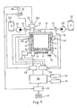
- Fig. 1 shows a schematic representation of an apparatus for foaming a refrigerator cabinet 10 having spaced apart external walls 11 and internal walls 12, defining spaces or gaps which must be completely filled with a layer 14 of a rigid foamed plastic material, made for example from a polyurethane foam,so as to thermally insulate and reinforce the walls of the cabinet.
- the refrigerator cabinet 10 is placed, in the known way, in a foaming jig 15 having opposing outer walls 16, on all sides of the refrigerator cabinet 10, a supporting base plate 17 and a plug member 18 which penetrates into the cabinet 10 and which fits to the internal surfaces of the latter.
- Reference 19 shows a schematic representation of a conveyor for loading and unloading the refrigerator cabinets 10, which is driven by an electric motor 20.
- the foaming jig 15 can obviously be of any suitable type, and can generally be opened automatically, in a per se known way, for the introduction and removal of the individual cabinets 10.
- the polyurethane mixture or foamable plastic material can be fed in any suitable way, for example by means of a high-pressure mixing head 21 comprising a control portion 21a and a mixing chamber 21b into which the chemical components to be mixed, which are contained in tanks 22, 23, are injected under high pressure by means of their respective metering pumps 24 and 25.
- the apparatus shown also comprises a processing unit 02 CPU 26 which controls the operation of the apparatus in relation to one or more significant parameters of the entire foaming process such as the pressure exerted by the foam on the walls of the cabinet and the like, the temperature of the same cabinet and/or of the foaming jig or mould, in one or more prefixed points.
- a processing unit 02 CPU 26 which controls the operation of the apparatus in relation to one or more significant parameters of the entire foaming process such as the pressure exerted by the foam on the walls of the cabinet and the like, the temperature of the same cabinet and/or of the foaming jig or mould, in one or more prefixed points.
- a first pressure sensor senses the pressure of the foam 14 developing inside the walls of the cabinet 10 and sends a pressure signal proportional to the varying value of the pressure exerted by the polyurethane foam against the walls of the regrigerator cabinet, to analog inputs 28 of the processing unit 26;
- a second sensor 29 and a third sensor 30 in turn send signals indicating the changes in temperatures of the refrigerator cabinet 10 and, respectively, of the foaming jig 15, to analog inputs 28 of the processing unit 26.
- the processing unit 26 is also provided with data relative to the rates of flow of the chemical components to be mixed, by means of flow transducers 31, 32, as shown schematically.
- References 33 and 34 in figure 1 indicate a keyboard for programming the processing unit with reference data, and a control monitor.
- the various temperature and pressure sensors can be of any suitable type; in particular, the pressure sensor 27 can be a normal pressure sensor which either senses the thrust exerted by the foam on the outer walls 13 of the cabinet directly, or indirectly by means of the mechanical stress exerted on the foaming jig.
- the various specific solutions may be determined each time in relation to the particular type of apparatus, the geometry and the configuration of the refrigerator cabinet and/or door to be foamed .
- the opening and closing conditions of the mixing head 21 are controlled by a further sensor 35 whose signal is sent to the digital inputs of the processing unit 26, as shown; these inputs 36 also receive a reference signal indicating a pre-established drop in the pressure of the polyurethane foam in the refrigerator cabinet 10, during each foaming operation for the purposes explained further on, for example by means of a decade counter 37 which can be set manually, or other suitable means.
- the digital outputs 38 of the processing unit 26 are operatively connected to the control cicuit of the motor 20 of the conveyor 19 of the foaming jig and, respectively, to a control valve 39 for a power supply 40 of the hydraulic circuit actuating the mixing head 21.
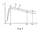
- the demolding time ts is established in relation to a variation of a pre-established value of at least one of the processing parameters, with respect to a reference value, for example in relation to a percent drop or reduction of the pressure with respect to the peak pressure Pp, of a pre-established value, by means of the decade counter 37.
- the most significant data of the foaming process, relative to the reference curve A, are stored in the memory of the processing unit 26 which contains the general programme of the apparatus.
- the first foaming operation will be carried out with an estimated degree of overpacking of mixture for the reference curve A; however, it is possible that the real pressure curve may differ slightly from the curve A if, for example, the system is not yet operating at full capacity and that the peak value is consequently slightly lower than the theoretical peak value Pp memorized in the processing unit 26 for the curve A; this real peak pressure value is stored in the processing unit.
- the pressure of the foam gradually begins to drop in accordance with curve A of figure 2.
- the pressure P has dropped with re spect to the peak pressure Pp of a value pre-established in percent in the processing unit 26, which is determined by means of the decade counter 37, the foam 14 inside the walls of the refrigerator cabinet will be considered to have hardened sufficiently and will have adhered to the internal surfaces of the walls 11 and 12 of the cabinet in such a way as to counteract and overcome the remaining pressure inside the foam itself.
- the discharging only takes place in relation to certain processing parameters, which are controlled and compared with corresponding reference parameters stored in the unit 26.
- the discharging or demolding moment depends therefore upon the actual foaming conditions, which may be modified from time to time and adapted, if necessary, to each subsequent foaming operation, in order to bring them as close as possible to the ideal foaming conditions of curve A.
- the foam pressure curve P depends both upon the temperature of the cabinet to be foamed, and upon the temperature of the foaming jig itself, as well as upon the quantity of mixture to be introduced into the gap between the walls of the cabinet, or upon the percentage of excess of mixture or overpacking generally required in order to ensure a complete and correct filling and the desired characteristics in the insulating layer thus formed.
- the quantity of mixture fed into the walls of the cabinet can be controlled by the processing unit and varied in relation to one or more parameters of the foaming process, for example by changing the percentage of overpacking according to the peak pressure reached during the foaming of a pre vious cabinet, and/or to the temperature of the cabinet and /or of the foaming jig itself; the quantity of overpacking or the percentage of said overpacking will be changed for example in the opposite way to the variation in the control parameter or parameters.
- the processing unit 26 sensing the previous peak value higher than that of curve A, sends a signal to the control members of the mixing head 21 to change their timing or the opening time of the head itself, thus reducing it in proportion to the variation it was subjected to by the peak pressure Pp, in order to bring the foaming condition of the subsequent cabinet back close to the foaming conditions of curve A; in this way, not only is it possible to ensure uniform and consistent results in the mass production of refrigerator cabinets, but also to save considerable quantities of insulating material.
- the method according to this invention is also advantageous from another standpoint; supposing in fact that for unforeseen reasons there is a sudden change, for example an increase, in the peak pressure but that, after the peak, the curing and hardening of the foam returns once more to the optimal curve A, or a very similar curve.
- Either one of the two above-mentioned pressure values, compared with a corresponding reference value of the processing unit, can serve for controlling the packing degree to which the cabinet and/or door are filled with expanded foam thus making it possible to immediately remedy the causes which gave rise to the irregular packing.
- the apparatus operates as follows: the data relating to the most important reference parameters which are to be controlled in the foaming process are introduced in the memory of the processing unit 26 by means of the key-board 33, and are obtained from previous foaming operations or operations specially carried out during the start-up of the system; a pre-established pressure drop per cent is defined, by means of the decade counter scaler 37 and then a cabinet 10 is introduced into the foaming jig 15 by means of the conveyor 19 controlled by the processing unit 26.
- the processing unit controls the opening time of the mixing head and then the quantity of mixture fed into the walls of the refrigerator cabinet; then, during the foaming step it controls the change in the pressure of the foam and, when said pressure has exceeded the peak value Pp and as dropped or reduced by the percent quantity determined in the processing unit itself, for example after a pressure drop of approximately 15-20% with respect to the peak pressure, the processing unit intervenes once again to control the aperture of the foaming jig and the discharge of the refrigerator cabinet by means of the conveyor 19.
- the signal of peak pressure of the foaming operation under way and any other important parameters of the foaming process carried out are memorized by the processing unit 26 and serve for controlling and correcting the foaming operation of the subsequent cabinet.
- the invention refers to a method for foaming cabinets and doors of refrigerators, freezers and the like, which makes use of a microprocessor-controller system for controlling the important parameters of the process and for demolding or discharging the cabinets after each foaming operation, in relation to the value reached by one or more parameters of the process itself, intervening from time to time in order to automatically correct or modify, so as to bring the foaming process back as close as possible to the foaming conditions considered as optimal thus ensuring greater utilization of the foaming plants and the production of insulation with uniform characteristics.
Landscapes
- Engineering & Computer Science (AREA)
- Mechanical Engineering (AREA)
- Chemical & Material Sciences (AREA)
- Combustion & Propulsion (AREA)
- Physics & Mathematics (AREA)
- Thermal Sciences (AREA)
- General Engineering & Computer Science (AREA)
- Casting Or Compression Moulding Of Plastics Or The Like (AREA)
- Refrigerator Housings (AREA)
- Extrusion Moulding Of Plastics Or The Like (AREA)
- Processing And Handling Of Plastics And Other Materials For Molding In General (AREA)
- Molding Of Porous Articles (AREA)
Abstract
The invention relates to a method and an apparatus for producing insulations (14) of foamed plastic material, in cabinets and doors of refrigerators, freezer and the like (10).
According to the invention, a metered quantity of a foamable mixture (14) is fed into the gaps between inner and outer walls (11, 12) of a cabinet or door (10), placed in a foaming jig (16); the foaming process is controlled by sensing characteristic parameters, for example, the temperature of the jig (16), cabinet or door (10), or the pressure of the foaming plastic material, comparing them with reference parameters or data stored in a data processing unit (26). A control signal is generated to open the foaming jig (10) and to demold the cabinet or door (10) when at least one of the processing parameters has reached a pre-established value. The metered quantity of mixture fed in each subsequent foaming operation is corrected each time according to the changes in the peak pressure of the foam (14) with respect to the previous foaming operation.
Description
- This invention relates to the production of insulation of foamed plastic material, and refers in particular to a method and an apparatus for producing foamed plastic insulations such as foamed polyurethane, in doors and cabinets for refrigerators, freezers and the like.
- We shall refer hereinafter to the production of insulations of foamed polyurethane, however it is obvious that the invention can be likewise applied and adapted for producing foamed insulations in any type of article and with any suitable type plastic material.
- In the manufacturing of cabinets and doors for refrigerators, freezers and the like, which make use of a rigid foam for the insulating material, the demolding time, that is to say, the length of time the cabinet or door remains in the press or foaming jig, greatly reduces the possibility of automating and improving the manufacturing process.
- In the foaming or refrigerator cabinets, for example with polyurethane material, to which reference will be made hereunder, the demolding time, that is to say, the length of time each cabinet must remain in the jig or mold until the foam has cured or reaches the desired degree of hardness, depends upon several parameters or variables of the foaming process, which include the temperature of refrigerator cabinets and the foaming jig, the percent of overpacking or excess of quantity of polyurethane mixture fed into the gaps or space between the outer and inner walls of the cabinet or in the door.
- At present, in the manifacturing or refrigerator cabinets and the like, the average demolding time or length of time the cabinet remains in the foaming jig, for a model of cabinet, is either calculated by trial and error at the beginning of each manufacturing cycle or derived from previous productions, with complicated operations which involve losses in terms of man-hours and manufacturing rejects.
- In practice, at the start of production, trial foaming operations are carried out on a number of refrigerator cabinets, varying both the length of time in which the cabinet remains in the jig and the percent of additional charge normally or overpacking of mixture required in order to ensure that it is properly filled, until the foaming conditions considered suitable for that particular cabinet or article to be manufactured are reached .
- According to the known manufacturing systems, the cabinets are demolded from the foaming jigs after a pre-established period of time, which remains constant throughout the entire production period ; however, as foaming conditions can vary during ma nufacturing, as a rule the length of time that the cabinets remain in the jigs is suitably extended so as to have a margin of safety in order to eliminate or at least reduce any possible problems to a minimum.
- This results in an excessively low productivity due to the considerable length of time that cabinets remain in the foaming jigs, and insufficient utilization of the productive capacities of the plants.
- This mode of operating proves to be impractical and gives rise to manufacturing rejects and an excessive consumption of material; furthermore, it does not ensure the manufacturing of insulation or article with constant uniform properties, due to the fact that certain parameters of the foaming process, in particular the pressure exerted by the gases in the polyurethane foam, change during the productive cycle.
- Consequently, it becomes necessary to carry out additional tests, sometimes operating with excess of overpacking and/or leaving the cabinet in the jig for excessively long periods, with respect to what would be necessary in actual fact.
- In an article by W.D. Clarke on Polyurethane Marketing & Technology - SPI 28 annual conference - November 1984, pages 194 and 197, a laboratory method has been proposed as an experiment in order to study the variables which affect the foaming process, considering the changes with time of the pressure of the foam inside a suitably modified Brett mold.
- In substance, W.D. Clarke maintained that he was able to calculate the demolding time by detecting the pressure curves of the polyols and comparing the pressure drops which occur after a given period of time have been elapsed, with respect to a specimen curve, starting from the peak pressure.
- Although W.D. Clarke proposes a simpler system for calculating the length of time the cabinet should remain in the foaming jig, in industrial use this does not give rise to any substantial difference due to the fact that the refrigerator cabinets will still have to be demolded after a pre-established and suitably prolonged period of time in order to make allowance for any possible changes in the parameters of the foaming process which will occur during manufacturing, without any possibility of controlling the foaming process or of intervening automatically in order to vary a subsequent foaming operation.
- The scope of this invention therefore is to provide a method and an apparatus for producing foamed plastic insulations in doors and cabinets of refrigerators, freezers and the like, by means of which it is possible to automatically control the foaming of a door or a cabinet closed in its respective foaming jig, and at the same time to establish, for each individual foaming operation, the most appropriate moment for demolding the foamed article, determining such moment each time no longer in relation to a pre-established length of time for the cabinet or door to remain in the foaming jig, but in relation to one or more suitably controlled characteristic parameters of the foaming process.
- A further scope of this invention is to provide a method and an apparatus as defined above, which enable the total automation of the operations of foaming and removing the foamed article from the jig, making it possible to intervene from time to time and to automatically modify certain parameters of the process, for example the percent of overpacking of mixture, if necessary, in order to maintain the most appropriate foaming conditions, without having to carry out additional tests.
- A still further scope of this invention is to provide a method and a foaming apparatus for foaming doors and cabinets of refrigerators, freezers and the like, with which it is possible to obtain a production of insulating material with substantial ly uniform and constant characteristics and which at the same time reduce the length of time that each single cabinet or each single door remains in the foaming jig, thereby ensuring higher productivity, greater utilization of the plants and immediate quality control.
- According to the invention, a metered quantity of a foamable mixture is fed into the gaps between inner and outer walls of a cabinet or door, placed in a foaming jig; the foaming process is controlled by sensing characteristic parameters, for example, the temperature of the jig, cabinet or door, or the pressure of the foaming plastic meterial, comparing them with reference parameters or data stored in a data processing unit. A control signal is generated to open the foaming jig and to demold the cabinet or door when at least one of the processing parameters has reached a pre-established value. The metered quantity of mixture fed in each subsequent foaming operation is corrected each time according to the changes in the peak pressure of the foam with respect to the previous foaming operation.
- The invention will be illustrated hereunder with reference to the example of the accompanying drawings, in which:
- Fig. 1 shows an apparatus operating according to the method of this invention;
- Fig. 2 is a graphic illustrating some foam pressure curves, in relation to time.
- Fig. 1 shows a schematic representation of an apparatus for foaming a
refrigerator cabinet 10 having spaced apartexternal walls 11 andinternal walls 12, defining spaces or gaps which must be completely filled with alayer 14 of a rigid foamed plastic material, made for example from a polyurethane foam,so as to thermally insulate and reinforce the walls of the cabinet. - The
refrigerator cabinet 10 is placed, in the known way, in afoaming jig 15 having opposingouter walls 16, on all sides of therefrigerator cabinet 10, a supportingbase plate 17 and aplug member 18 which penetrates into thecabinet 10 and which fits to the internal surfaces of the latter.Reference 19 shows a schematic representation of a conveyor for loading and unloading therefrigerator cabinets 10, which is driven by anelectric motor 20. Thefoaming jig 15 can obviously be of any suitable type, and can generally be opened automatically, in a per se known way, for the introduction and removal of theindividual cabinets 10. - The polyurethane mixture or foamable plastic material can be fed in any suitable way, for example by means of a high-
pressure mixing head 21 comprising acontrol portion 21a and amixing chamber 21b into which the chemical components to be mixed, which are contained intanks respective metering pumps - The apparatus shown also comprises a processing unit 02
CPU 26 which controls the operation of the apparatus in relation to one or more significant parameters of the entire foaming process such as the pressure exerted by the foam on the walls of the cabinet and the like, the temperature of the same cabinet and/or of the foaming jig or mould, in one or more prefixed points. In particular, a first pressure sensor, schematically indicated byreference 27, senses the pressure of thefoam 14 developing inside the walls of thecabinet 10 and sends a pressure signal proportional to the varying value of the pressure exerted by the polyurethane foam against the walls of the regrigerator cabinet, toanalog inputs 28 of theprocessing unit 26; asecond sensor 29 and athird sensor 30 in turn send signals indicating the changes in temperatures of therefrigerator cabinet 10 and, respectively, of thefoaming jig 15, toanalog inputs 28 of theprocessing unit 26. - The
processing unit 26 is also provided with data relative to the rates of flow of the chemical components to be mixed, by means offlow transducers References 33 and 34 in figure 1 indicate a keyboard for programming the processing unit with reference data, and a control monitor. The various temperature and pressure sensors can be of any suitable type; in particular, thepressure sensor 27 can be a normal pressure sensor which either senses the thrust exerted by the foam on the outer walls 13 of the cabinet directly, or indirectly by means of the mechanical stress exerted on the foaming jig. In any case, the various specific solutions may be determined each time in relation to the particular type of apparatus, the geometry and the configuration of the refrigerator cabinet and/or door to be foamed . - The opening and closing conditions of the
mixing head 21 are controlled by afurther sensor 35 whose signal is sent to the digital inputs of theprocessing unit 26, as shown; theseinputs 36 also receive a reference signal indicating a pre-established drop in the pressure of the polyurethane foam in therefrigerator cabinet 10, during each foaming operation for the purposes explained further on, for example by means of adecade counter 37 which can be set manually, or other suitable means. - Lastly, it can be seen from figure 1 that the
digital outputs 38 of theprocessing unit 26 are operatively connected to the control cicuit of themotor 20 of theconveyor 19 of the foaming jig and, respectively, to acontrol valve 39 for apower supply 40 of the hydraulic circuit actuating themixing head 21. - The foaming process will now be described, with reference to the graphical representation of figure 2, which gives in relation to time t, two curves A, B showing the variation in the process value of the pressure P exerted by the
foam 14 on the internal walls of therefrigerator cabinet 10, with the variation in the foaming conditions. In particular, it is assumed that the curve A of the graphical representation of figure 2 corresponds to the ideal foaming curve for a given model of refrigerator cabinet and for a given formulation of polyurethane mixture, calculated for example as an average of the initial trial foaming parameters or of foamings carried out previously; you will see from fig. 1 that as the foam rise, the foam pressure rise slowly until the gel time is reached; then the pressure rise rapidly up to a peak value Pp after which the pressure of the foam will decrease. It is also assumed that the most important processing parameters are the process temperatures Tm of the foaming jig, the process temperatures Ta of thecabinet 10 and the peak pressure Pp reached by the foam at the instant tp, the point ts corresponds to the instant that therefrigerator cabinet 10 is demolded or discharged from thefoaming jig 15. According to this invention, the demolding time ts is established in relation to a variation of a pre-established value of at least one of the processing parameters, with respect to a reference value, for example in relation to a percent drop or reduction of the pressure with respect to the peak pressure Pp, of a pre-established value, by means of thedecade counter 37. The most significant data of the foaming process, relative to the reference curve A, are stored in the memory of theprocessing unit 26 which contains the general programme of the apparatus. - The first foaming operation will be carried out with an estimated degree of overpacking of mixture for the reference curve A; however, it is possible that the real pressure curve may differ slightly from the curve A if, for example, the system is not yet operating at full capacity and that the peak value is consequently slightly lower than the theoretical peak value Pp memorized in the
processing unit 26 for the curve A; this real peak pressure value is stored in the processing unit. - As the foaming cycle proceeds, after having passed the peak value, and as the curing or hardening of the resin begins, the pressure of the foam gradually begins to drop in accordance with curve A of figure 2. When the pressure P has dropped with re spect to the peak pressure Pp of a value pre-established in percent in the
processing unit 26, which is determined by means of thedecade counter 37, thefoam 14 inside the walls of the refrigerator cabinet will be considered to have hardened sufficiently and will have adhered to the internal surfaces of thewalls foam 14 has hardened against theinternal walls processing unit 26 and corresponds to the instant Ts1 that the cabinet is discharged from thefoaming jig 15. Consequently, unlike conventional foaming systems in which the foamed articles are discharged after a pre-established period of time, which remains unchanged in the subsequent foaming operations, without any specific control during the foaming process, according to this invention the discharging only takes place in relation to certain processing parameters, which are controlled and compared with corresponding reference parameters stored in theunit 26. The discharging or demolding moment depends therefore upon the actual foaming conditions, which may be modified from time to time and adapted, if necessary, to each subsequent foaming operation, in order to bring them as close as possible to the ideal foaming conditions of curve A. - In fact, as mentioned previously, the foam pressure curve P depends both upon the temperature of the cabinet to be foamed, and upon the temperature of the foaming jig itself, as well as upon the quantity of mixture to be introduced into the gap between the walls of the cabinet, or upon the percentage of excess of mixture or overpacking generally required in order to ensure a complete and correct filling and the desired characteristics in the insulating layer thus formed.
- Consequently, according to a further feature of this invention, in order to obtain insulating material with uniform and unchanging characteristics, and at the same time in order to avoid overfilling the
refrigerator cabinets 10, that may result in a waste of material, or of underfilling them, the quantity of mixture fed into the walls of the cabinet can be controlled by the processing unit and varied in relation to one or more parameters of the foaming process, for example by changing the percentage of overpacking according to the peak pressure reached during the foaming of a pre vious cabinet, and/or to the temperature of the cabinet and /or of the foaming jig itself; the quantity of overpacking or the percentage of said overpacking will be changed for example in the opposite way to the variation in the control parameter or parameters. - It is assumed in fact that, due to an increase in temperature, or for other reasons, the pressure curve for a given foaming operation proves to be the upper curve B, the peak pressure changes from the value Pp of curve A to the value Pp of curve B. It is obvious that under these conditions, with an equal pressure drop per cent, the moment the cabinet is discharged from the jig changes from Ts1 to Ts2, thereby increasing the length of time that the
cabinet 10 remains in the foaming jig; the cabinet will still be discharged however when the pressure P has dropped by the same per cent value as the previous operations, under conditions considered suitable for opening the jig. As the quantity of mixture fed into the walls of the cabinet now proves to be excessive, and in order to bring the pressures and the characteristics of the layer of insulating material back to the desired levels, according to the method of this invention, theprocessing unit 26, sensing the previous peak value higher than that of curve A, sends a signal to the control members of themixing head 21 to change their timing or the opening time of the head itself, thus reducing it in proportion to the variation it was subjected to by the peak pressure Pp, in order to bring the foaming condition of the subsequent cabinet back close to the foaming conditions of curve A; in this way, not only is it possible to ensure uniform and consistent results in the mass production of refrigerator cabinets, but also to save considerable quantities of insulating material. - The method according to this invention is also advantageous from another standpoint; supposing in fact that for unforeseen reasons there is a sudden change, for example an increase, in the peak pressure but that, after the peak, the curing and hardening of the foam returns once more to the optimal curve A, or a very similar curve. It is clear that under these conditions, if the demolding time ts only depended upon a per cent variation in the pressure, referred to the peak pressure of the process under way, the cabinet would be discharged at a later moment, and would remain longer in the foaming jig, or if it were to be discharged or demolded at the moment tsl of curve A, it could present an excessively high residual pressure which would cause the cabinet to bulge. Consequently, as an alternative, it is also possible to control and to make a comparison between the peak pressure, as mentioned previously, and the residual pressures, at the moment of demolding in order to cont rol or to change the moment that the jig opens and the cabinet is discharged. Either one of the two above-mentioned pressure values, compared with a corresponding reference value of the processing unit, can serve for controlling the packing degree to which the cabinet and/or door are filled with expanded foam thus making it possible to immediately remedy the causes which gave rise to the irregular packing.
- In practice, the apparatus operates as follows: the data relating to the most important reference parameters which are to be controlled in the foaming process are introduced in the memory of the
processing unit 26 by means of the key-board 33, and are obtained from previous foaming operations or operations specially carried out during the start-up of the system; a pre-established pressure drop per cent is defined, by means of thedecade counter scaler 37 and then acabinet 10 is introduced into thefoaming jig 15 by means of theconveyor 19 controlled by theprocessing unit 26. On the basis of the programme memorized in it and on the basis of the data received from the various sensing means, the processing unit controls the opening time of the mixing head and then the quantity of mixture fed into the walls of the refrigerator cabinet; then, during the foaming step it controls the change in the pressure of the foam and, when said pressure has exceeded the peak value Pp and as dropped or reduced by the percent quantity determined in the processing unit itself, for example after a pressure drop of approximately 15-20% with respect to the peak pressure, the processing unit intervenes once again to control the aperture of the foaming jig and the discharge of the refrigerator cabinet by means of theconveyor 19. The signal of peak pressure of the foaming operation under way and any other important parameters of the foaming process carried out, are memorized by theprocessing unit 26 and serve for controlling and correcting the foaming operation of the subsequent cabinet. - It is clear therefore, from what has been described and shown in the accompanying drawings, that the invention refers to a method for foaming cabinets and doors of refrigerators, freezers and the like, which makes use of a microprocessor-controller system for controlling the important parameters of the process and for demolding or discharging the cabinets after each foaming operation, in relation to the value reached by one or more parameters of the process itself, intervening from time to time in order to automatically correct or modify, so as to bring the foaming process back as close as possible to the foaming conditions considered as optimal thus ensuring greater utilization of the foaming plants and the production of insulation with uniform characteristics.
Claims (14)
1. A method for producing insulations (14) of foamed plastic materials in cabinets and doors of refrigerators, freezers and the like (10), characterized by comprising the steps of: feeding a metered quantity of a foamable mixture into the spaces between outer and inner walls (11, 12) of the cabinet, door or the like (10) positioned in a foaming jig (16, 17): letting the foamable mixture (14) to expand until it fills the aforesaid spaces;sensing change of value for at least one of foaming process parameters and memorizing data in a data processing unit (26) during each foaming operation; comparing said sensed parameter with a reference parameter memorized in the data processing unit (26) and emitting a control signal by said data processing unit (26) to control the demolding of the cabinet, door and the like (10) from the foaming jig (16, 17) after the sensed value of said at least one process parameter has undergone a variation of a pre-established quantity with respect to a reference value of said reference parameter.
2. A method as claimed in claim 1, characterized in that said foaming process parameters, are selected from the following ones: the pressure exerted by the foam on the walls of the cabinet and the like; the peak value of said pressure; the temperature of the cabinet and the like (10); the tem perature of the foaming jig (16, 17); and the metered amount of the foaming mixture feed into said cabinet or the like (10).
3. A method as claimed in claim 1 characterized by comprising the step of changing the process value of said foaming process parameters for a subsequent foaming operation, in relation to the process value of the same parameter obtained during at least one of a previous foaming operation.
4. A method as claimed in claim 1 characterized by comprising the step of emitting a control signal by said processing unit (26) to cause the cabinet (10) and the like to be unlooded from the jig (16, 17) after the pressure value exerted by the foam on the walls (11, 12) has been reduced by a pre-established quantity with respect to a reference pressure value.
5. A method as claimed in claim 1, characterized by comprising the step of emitting a control signal by said processing unit (26) to cause the cabinet (10)and the like to be unloaded from the jig (16, 17) after the pressure value exerted by the foam on the walls (11, 12) has decreased by a pre-established quantity in percentage, with respect to the peak value of the foam pressure.
6. A method as claimed in claim 3, characterized by further comprising the step of changing the metered quantity of the mixture fed into the cabinet (10) or the like, in relation to the maximum pressure reached by the foam (14) in a previous foaming operation.
7. A method as claimed in claim 6, in which a metered quantity of mixture including a packing or extra amount of mixture is fed into the cabinet (10) or the like characterized by comprising the step of changing said extra amount of mixture for a foaming operation subsequant to a previous one, correspondingly to the changes of the pressure value in said previous foaming operation with respect to a reference pressure value, memorized in said data processing unit (26).
8. A method as claimed in claim 7, further characterized by comprising the step of controlling the packing degree of the cabinet (10) or the like, by comparing peak pressure values of the foam (14).
9. A method as claimed in claim 8, characterized by comprising the step of controlling the packing degree of the cabinet or the like by comparing the peak pressure and/or the pressure of the foam (14) at the moment of discharging the cabinet and the like (10) from the foaming jig (16, 17).
10. An apparatus for producing foamed plastic insulations according to the method claimed in the previous claims, in particular for doors and cabinets (10) of refrigerators, freezers and the like, comprising a foaming jig (16, 17) in which the cabinet (10) or the like is enclosed during the foaming operation, said apparatus comprising power actuated conveyor means (19) for loading and unloading the cabinets (10) from the foaming jig (16, 17), at least one mixing head (21) for feeding a mixture of chemical components, operatively connected to a control circuit (39) acting to open and to close the mixing head (21), characterized by the fact of comprising first sensing means (35) for sensing the opened and closed conditions of the head (21), the apparatus further comprising: a programmable data processing unit (26) having data inputs (28) and control signal outputs (38), second sensing means (27, 29, 30) for sensing at least one characteristic parameter of the foaming process, said second sensing means (27,29,30) being operatively connected to the data input (28) of the processing unit (26); and an operative connection between second data input (36) of the data processing unit and said first sensing means (35) of the mixing head, as well as an operative connection between said control signal output (38) of the processing unit (26), said power actuated conveyor (20) and, respectively, a control device (39) of the mixing head control circuit; said data proces sing unit (26) being programmed for timing the aperture of the mixing head (21) in order to feed a pre-established quantity of mixture and, respectively to control the actuation of said conveyor means (20) in the jig (16, 17), when the aforesaid parameter of the foaming process has undergone a variation of a pre-established value with respect to value of a reference parameter memorized in said data processing unit (26).
11. An apparatus as claimed in claim 10 characterized by that said second sensing means comprise pressure sensing means (27) for sensing the pressure exerted by the foam against the walls of the cabinet or the like in the foaming jig.
12. An apparatus as claimed in claim 10 and 11, further characterized by comprising a temperature sensing means (29, 30) for sensing the temperature of the cabinet or the like, in the foaming jig and, respectively, for sensing the temperature of the foaming jig.
13. An apparatus as claimed in claim 10, characterized in that the data processing unit (26) is programmed to vary the quantity of mixture fed by the mixing head (21), according to the changes in the value of a characteristic parameter of the foaming process.
14. Apparatus as claimed in claim 13, characterized in that the data processing unit (26) is programmed to vary the metered quantity of mixture to be fed by the mixing head (21) during a subsequent foaming operation, inversely to the changes of the pressure peak value for an outstanding foaming operation with respect to the pressure peak pressure of a previous operation.
Applications Claiming Priority (2)
| Application Number | Priority Date | Filing Date | Title |
|---|---|---|---|
| IT1913086 | 1986-01-21 | ||
| IT19130/86A IT1204767B (en) | 1986-01-21 | 1986-01-21 | PROCEDURE AND EQUIPMENT FOR THE PRODUCTION OF INSULATIONS IN EXPANDED MATERIAL, IN REFRIGERATORS, FREEZERS AND SIMILAR |
Publications (2)
| Publication Number | Publication Date |
|---|---|
| EP0230921A2 true EP0230921A2 (en) | 1987-08-05 |
| EP0230921A3 EP0230921A3 (en) | 1989-07-05 |
Family
ID=11155060
Family Applications (1)
| Application Number | Title | Priority Date | Filing Date |
|---|---|---|---|
| EP87100500A Withdrawn EP0230921A3 (en) | 1986-01-21 | 1987-01-16 | Method and apparatus for foaming insulations in refrigerators and the like |
Country Status (4)
| Country | Link |
|---|---|
| US (1) | US4765935A (en) |
| EP (1) | EP0230921A3 (en) |
| JP (1) | JPS62208911A (en) |
| IT (1) | IT1204767B (en) |
Cited By (3)
| Publication number | Priority date | Publication date | Assignee | Title |
|---|---|---|---|---|
| EP0328185A3 (en) * | 1988-02-10 | 1991-07-31 | GESTIONI RIUNITE TOSCANA GOMMA S.p.A. | Method and apparatus for marking irregularly produced foam articles |
| ITMI20100415A1 (en) * | 2010-03-15 | 2011-09-16 | Afros Spa | METHOD AND EQUIPMENT FOR THE DISTRIBUTION OF A POLYURETHANE MIXTURE IN CABLES. |
| IT201900024949A1 (en) * | 2019-12-20 | 2021-06-20 | Cannon Spa | METHOD AND EQUIPMENT FOR DELIVERING A SPLIT-FREE POLYMER BLEND |
Families Citing this family (11)
| Publication number | Priority date | Publication date | Assignee | Title |
|---|---|---|---|---|
| US5079928A (en) * | 1989-07-07 | 1992-01-14 | Rocky Research | Discrete constant pressure staging of solid-vapor compound reactors |
| US5169574A (en) * | 1991-08-08 | 1992-12-08 | Ford Motor Company | Adjustable clamp load for producing a foamed panel |
| US5207957A (en) * | 1991-08-08 | 1993-05-04 | Ford Motor Company | Method for producing a foamed panel |
| US5693271A (en) * | 1994-09-01 | 1997-12-02 | Chase Industries, Inc. | Rotationally molding an insulated plastic molded door with integral hinge |
| JP2002001751A (en) * | 2000-06-16 | 2002-01-08 | Jsr Corp | Method for producing foam and apparatus for producing foam |
| US6398995B1 (en) | 2000-10-10 | 2002-06-04 | Chase Industries Inc. | Rotationally molded door with integrally molded hinge member |
| AU2003277672A1 (en) * | 2002-11-11 | 2004-06-03 | Sunstar Suisse Sa | Method and apparatus for foam molding |
| ITMI20041609A1 (en) * | 2004-08-05 | 2004-11-05 | Crios Spa | PROCESS AND EQUIPMENT FOR VACUUM FOAMING OF REFRIGERATED CABINETS |
| NZ564047A (en) * | 2007-12-03 | 2010-04-30 | Airfoama Developments Ltd | Mixing apparatus |
| DE102010043329A1 (en) * | 2010-11-03 | 2012-05-03 | Bayer Materialscience Aktiengesellschaft | Process for the production of foamed moldings |
| ITUB20151122A1 (en) * | 2015-05-29 | 2016-11-29 | Krauss Maffei Tech Gmbh | APPARATUS FOR FOAMING REFRIGERATORS AND RELATED FOAMING METHOD |
Family Cites Families (11)
| Publication number | Priority date | Publication date | Assignee | Title |
|---|---|---|---|---|
| US3265784A (en) * | 1963-04-02 | 1966-08-09 | Gen Motors Corp | Method for the manufacture of a foam insulated cabinet wherein the cabinet is cooled during the molding to prevent bulging |
| US3628901A (en) * | 1969-07-15 | 1971-12-21 | New Britain Machine Co | Means for monitoring product quality in a plastics injection-molding machine |
| US3937776A (en) * | 1971-11-01 | 1976-02-10 | Usm Corporation | Method for controlling injection molding machines |
| US3893792A (en) * | 1973-04-06 | 1975-07-08 | Bbf Group Inc | Controller for injection molding machine |
| US3859400A (en) * | 1974-01-11 | 1975-01-07 | Cincinnati Milacron Inc | Method for injection molding machine automatic control |
| US4094940A (en) * | 1974-01-21 | 1978-06-13 | Usm Corporation | Injection molding machine controls |
| US4399105A (en) * | 1981-03-30 | 1983-08-16 | The Upjohn Company | Programmable computer controlled reaction injection mixing head system |
| JPS57182411A (en) * | 1981-05-08 | 1982-11-10 | Hitachi Ltd | Foam molding device of synthetic resin foaming agent |
| DE3243632A1 (en) * | 1982-11-25 | 1984-05-30 | Flewu AG, 9000 St. Gallen | METHOD AND DEVICE FOR SINTERING, IN PARTICULAR, DIFFERENT MOLDINGS MADE OF PARTICULARLY DIFFERENT FOAMABLE PLASTICS |
| IT1163758B (en) * | 1983-07-12 | 1987-04-08 | Eurodomestici Ind Riunite | PERFECTED METHOD FOR THE PRODUCTION OF FURNITURE AND THEIR DOORS OF REFRIGERATING APPLIANCES AND SYSTEM FOR IMPLEMENTING THE METHOD |
| JPS60112430A (en) * | 1983-11-25 | 1985-06-18 | Sekisui Koki Seisakusho:Kk | Controlling method of foamed polystyrene molding |
-
1986
- 1986-01-21 IT IT19130/86A patent/IT1204767B/en active
-
1987
- 1987-01-16 EP EP87100500A patent/EP0230921A3/en not_active Withdrawn
- 1987-01-20 US US07/004,495 patent/US4765935A/en not_active Expired - Fee Related
- 1987-01-20 JP JP62009200A patent/JPS62208911A/en active Pending
Cited By (6)
| Publication number | Priority date | Publication date | Assignee | Title |
|---|---|---|---|---|
| EP0328185A3 (en) * | 1988-02-10 | 1991-07-31 | GESTIONI RIUNITE TOSCANA GOMMA S.p.A. | Method and apparatus for marking irregularly produced foam articles |
| ITMI20100415A1 (en) * | 2010-03-15 | 2011-09-16 | Afros Spa | METHOD AND EQUIPMENT FOR THE DISTRIBUTION OF A POLYURETHANE MIXTURE IN CABLES. |
| EP2366525A1 (en) | 2010-03-15 | 2011-09-21 | Afros S.P.A. | Method and apparatus for feeding a polyurethane mixture into hollow bodies |
| US8709313B2 (en) | 2010-03-15 | 2014-04-29 | Afros S.P.A. | Method and apparatus for feeding a polyurethane mixture into hollow bodies |
| IT201900024949A1 (en) * | 2019-12-20 | 2021-06-20 | Cannon Spa | METHOD AND EQUIPMENT FOR DELIVERING A SPLIT-FREE POLYMER BLEND |
| EP3838567A1 (en) | 2019-12-20 | 2021-06-23 | Cannon S.p.A. | Method and apparatus for pouring a spatter free polymeric mixture |
Also Published As
| Publication number | Publication date |
|---|---|
| US4765935A (en) | 1988-08-23 |
| JPS62208911A (en) | 1987-09-14 |
| IT8619130A0 (en) | 1986-01-21 |
| EP0230921A3 (en) | 1989-07-05 |
| IT1204767B (en) | 1989-03-10 |
Similar Documents
| Publication | Publication Date | Title |
|---|---|---|
| US4765935A (en) | Method for foaming insulations in refrigerators and the like | |
| US4800050A (en) | Adaptive control process for foaming and fusing plastics | |
| US6108587A (en) | Injection molding controller with machine modeling | |
| US5756017A (en) | Method of simulating resin behavior in press molding | |
| US5002475A (en) | Reaction injection molding apparatus | |
| US4714579A (en) | Method and an apparatus for the production of shaped articles | |
| US11826933B2 (en) | Foam molding method and injection molding machine | |
| US10211471B2 (en) | Apparatus for controlling purging in a hydrogen storage system and method for the same | |
| US11571845B2 (en) | Method for determining a target value of a state variable | |
| CN110394956B (en) | Method for determining the dissolution state of a gas | |
| EP3031594B1 (en) | Injection control method, and injection control device | |
| WO2010088844A1 (en) | Synchronized control of hot-runners for multi-cavity injection molding | |
| EP3638479B1 (en) | Injection molding of crosslinking polymers | |
| US6861018B2 (en) | Temperature control method and apparatus for injection molding structure | |
| Sanschagrin | Process control of injection molding | |
| CN120481229B (en) | Initial process parameter determining method and device, electronic equipment and storage medium | |
| EP3863827B1 (en) | Method and system for improving the production of a cased device | |
| US6468460B2 (en) | Method for manufacturing heat-curable resin molded product | |
| Pantani et al. | Analysis of gate freeze‐off time in injection molding | |
| US5250241A (en) | Method for forming molded portion at end of extruded weather strip | |
| KR100360420B1 (en) | Gas supplier for making foamed plastic | |
| JP3292622B2 (en) | Injection control device of injection molding machine | |
| US20130285274A1 (en) | Methods and apparatus for processing polymers | |
| JP2008302599A (en) | Control method of injection molding machine | |
| US5599487A (en) | Method and device for fabricating plastic objects from thermoplastic material |
Legal Events
| Date | Code | Title | Description |
|---|---|---|---|
| PUAI | Public reference made under article 153(3) epc to a published international application that has entered the european phase |
Free format text: ORIGINAL CODE: 0009012 |
|
| AK | Designated contracting states |
Kind code of ref document: A2 Designated state(s): DE FR GB |
|
| PUAL | Search report despatched |
Free format text: ORIGINAL CODE: 0009013 |
|
| AK | Designated contracting states |
Kind code of ref document: A3 Designated state(s): DE FR GB |
|
| STAA | Information on the status of an ep patent application or granted ep patent |
Free format text: STATUS: THE APPLICATION IS DEEMED TO BE WITHDRAWN |
|
| 18D | Application deemed to be withdrawn |
Effective date: 19900106 |
|
| RIN1 | Information on inventor provided before grant (corrected) |
Inventor name: FIORENTINI, CARLO |