EP0233032A2 - Fixation d'un rail - Google Patents
Fixation d'un rail Download PDFInfo
- Publication number
- EP0233032A2 EP0233032A2 EP87300885A EP87300885A EP0233032A2 EP 0233032 A2 EP0233032 A2 EP 0233032A2 EP 87300885 A EP87300885 A EP 87300885A EP 87300885 A EP87300885 A EP 87300885A EP 0233032 A2 EP0233032 A2 EP 0233032A2
- Authority
- EP
- European Patent Office
- Prior art keywords
- shoe
- anchorage
- cam
- base
- rail
- Prior art date
- Legal status (The legal status is an assumption and is not a legal conclusion. Google has not performed a legal analysis and makes no representation as to the accuracy of the status listed.)
- Withdrawn
Links
- 238000003466 welding Methods 0.000 claims abstract 2
- 239000000945 filler Substances 0.000 claims 1
- 239000002184 metal Substances 0.000 abstract description 2
- 229910000639 Spring steel Inorganic materials 0.000 description 2
- 238000005266 casting Methods 0.000 description 2
- 210000003141 lower extremity Anatomy 0.000 description 2
- 238000010276 construction Methods 0.000 description 1
- 238000012986 modification Methods 0.000 description 1
- 230000004048 modification Effects 0.000 description 1
- 210000001364 upper extremity Anatomy 0.000 description 1
- 230000003313 weakening effect Effects 0.000 description 1
Images


Classifications
-
- E—FIXED CONSTRUCTIONS
- E01—CONSTRUCTION OF ROADS, RAILWAYS, OR BRIDGES
- E01B—PERMANENT WAY; PERMANENT-WAY TOOLS; MACHINES FOR MAKING RAILWAYS OF ALL KINDS
- E01B9/00—Fastening rails on sleepers, or the like
- E01B9/66—Rail fastenings allowing the adjustment of the position of the rails, so far as not included in the preceding groups
-
- E—FIXED CONSTRUCTIONS
- E01—CONSTRUCTION OF ROADS, RAILWAYS, OR BRIDGES
- E01B—PERMANENT WAY; PERMANENT-WAY TOOLS; MACHINES FOR MAKING RAILWAYS OF ALL KINDS
- E01B23/00—Easily dismountable or movable tracks, e.g. temporary railways; Details specially adapted therefor
- E01B23/10—Shiftable tracks for heavy loads, e.g. carrying excavators
- E01B23/14—Fastening or joining means
-
- E—FIXED CONSTRUCTIONS
- E01—CONSTRUCTION OF ROADS, RAILWAYS, OR BRIDGES
- E01B—PERMANENT WAY; PERMANENT-WAY TOOLS; MACHINES FOR MAKING RAILWAYS OF ALL KINDS
- E01B9/00—Fastening rails on sleepers, or the like
- E01B9/38—Indirect fastening of rails by using tie-plates or chairs; Fastening of rails on the tie-plates or in the chairs
- E01B9/44—Fastening the rail on the tie-plate
- E01B9/46—Fastening the rail on the tie-plate by clamps
Definitions
- This invention relates to anchorages for railtracks, more particularly heavy duty tracks as used for supporting extremely heavy moving loads such as "Goliath” cranes.
- the invention may however be applied to certain railtracks designed for other purposes.
- adjustable anchorage includes a rotary eccentric cam mounted on a stationary bolt which may be welded to the stationary sole plate on which the track rail is supported.
- the cam engages a laterally movable shoe which in turn engages part of the track rail, such that by turning the cam the lateral abutment for the rail is altered in position.
- a nut on the bolt is tightened down to fix the cam in position.
- a problem arising in this design is that the heavy lateral forces generated by the movement of large loads along the rail may apply excessive lateral stresses to the bolt.
- the bolt may also be required to absorb vertical lifting forces generated by rise and fall of the rail as a load moves lengthwise. Accordingly it is an object of the invention to provide an improved anchorage which will reduce problems arising from over-stressing of the bolts.
- the invention is based on the concept of transferring the forces from the bolt onto other components, and broadly stated the invention consists in an adjustable anchorage for a railtrack, comprising a stationary base secured to a mounting surface and having a rigid abutment surface of circular profile in plan, an adjustable anchorage shoe having a locating surface to engage the base flange of the rail, directly or indirectly, and a circular bearing surface, and a rotary adjusting cam having an inner circular surface to engage the circular profile of the rigid abutment and an outer eccentric circular surface to engage the circular bearing surface on the adjustable shoe.
- the anchorage includes a clamp for fixing the adjustment cam in any selected position, the clamp including a bridge which spans across and above the cam.
- the clamp may include a wedge, tightening bolt, or the equivalent engaging the bridge and bearing on the cam.
- the anchorage comprises a base casting 10 securely welded at 11 around three sides to an underlying metal sole plate 12 which also supports the track rail 13.
- the track rail has a vertical web 14 and a bottom flange 15.
- the anchorage base 10 has an integral rigid upstanding circular boss 18 and over this is loosely mounted a circular eccentric adjusting cam 19 having a circular internal profile 20 engaging the boss 18 and a circular external profile 21 which is a loose fit in a circular socket 22 formed in an adjustable anchorage shoe 23.
- This shoe has a generally flat plate portion 25 lying on the upper face of the base 10 and a pair of legs or feet 27 which rest on the sole plate 12 and engage the adjacent edge 28 of the bottom flange 15 of the rail.
- the shoe 23 also has a projecting nose 30 which overhangs the bottom rail flange 15 and is preferably spaced from the flange to give clearance for the rail to lift to a limited extent.
- a spring (not illustrated) may be incorporated below this nose.
- the adjusting cam 19 is provided with means for rotating the cam about the vertical centreline of the boss 18 to adjust the shoe laterally as required. It is also important that the overall height of the anchorage should be at a minimum to avoid the anchorage being fouled by the driving gear of a crane or other machine moving along the track rail.
- the cam has a shallow flange 31 of hexagonal profile lying above the top face of the shoe 23 so that a large spanner can be used to turn the cam.
- the cam may be sunk below the level of the top face of the shoe, and formed with a pair of sockets or a square recess in its upper face to allow it to be turned by a special tool without the need for any part projecting above the top face of the shoe.
- the anchorage includes a bridge 40 having two upstanding pillars 41 on opposite sides, and a horizontal span 42 bridging across between the pillars over the cam.
- a pair of wedges 43 can be driven in opposite directions into the gap between the span of the bridge and the upper face of the cam, and the wedges may have transverse grooves or serrations to allow a locking wedge to be driven in at right angles.
- a clamping bolt 46 may be provided, in a screw-thread aperture in the bridge span, to bear down on the upper surface of the cam and prevent movement after the final adjustment.
- the eccentric cam after adjustment is fixed in position by means of a pin 49 driven through an aperture 47 in the base casting.
- the pin thus locates the cam rotationally and if the cam is provided with a top flange, as shown at 47, the pin also acts to hold the shoe down against the track rail. If a "roll pin” is used as a pin the resilient expansion of the roll pin will hold it firmly in position.
- a series of angularly spaced apertures or recesses are formed around its periphery.
- this anchorage provides large rigid abutment surfaces through which the loads from the track rail are transmitted to the sole plate and avoids the weakening associated with the use of a clamping bolt extended upwards from the sole plate through the adjusting cam.
- the circular cam fits over a rigid upstanding boss, but the invention can be applied to an arrangement in which the cam has a rigid boss fitting in a recess in the base plate.
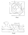
- the bottom flange 15 of the track rail rests on the underlying sole plate 12, with an intervening pad 9, and is located by an anchorage comprising a base 50 which is welded to the sole plate, and an anchorage clip 51 which has a nose 52 overlying the track rail with a clearance, and a vertical abutment flange 53 which forms a locating shoulder to bear against the edge of the rail flange 15.
- the anchorage clip 51 is generally rectangular in plan as seen in Figure 5 and is movable in the direction of the arrow X towards and away from the track rail through an opening or tunnel 56 formed by an arch 57 formed integral with the base 50.
- this anchorage clip On its underside this anchorage clip has a downward projection 58 which fits into a depression 59 in the underside of the tunnel and the abutting transverse shoulders 60 are inclined, as illustrated at 61 in Figure 5, so that the final position of the clip in the direction X can be adjusted by movement of the clip laterally in the direction Y.
- the anchorage clip 51 can be introduced into position from the right in Figure 6 and then lowered to engage the cam shoulders 60 after which the clip is located by a transverse wedge 62, which is inserted laterally into the clearance gap above the anchorage clip, the wedge being restrained by a shallow rib 63 on its upper surface. If required further wedges 64 may be inserted into the same tunnel along the flanks of the anchorage clip 51 to hold it in position.
- the anchorage again comprises an anchorage clip 71 positioned within a tunnel opening 72 in an anchorage block 73 which is welded to the sole plate 12.
- the anchorage clip 71 is formed with an inclined transverse flange 74 on its underside fitting within a corresponding inclined transverse groove 75 in the anchorage block such that lateral movements of the clip in the direction Y likewise cause adjustment of its position in the direction X.
- the anchorage clip is held in position by a spring steel U-clip 76 whose lower limb 77 engages between the upper surface of the clip 71 and the top part 78 of the tunnel arch.
- the adjustable anchorage clip 80 fits over a fixed anchorage base 81, which is welded to the sole plate 12 and its position in the direction of arrow X is adjustable by means of an eccentric rotary cam 82, which has a circular boss 83 fitting in a socket 84 in the anchorage clip and a further eccentric socket 85 fitting over a rigid spigot 86 integral with the base 81.
- eccentric rotary cam 82 which has a circular boss 83 fitting in a socket 84 in the anchorage clip and a further eccentric socket 85 fitting over a rigid spigot 86 integral with the base 81.
- the rotary cam is held in position by a separate spring steel clip 88, which has a lower limb 89 engaging below part of the base 81 and an upper limb 90 which fits over the top of the rotary cam and has a small rounded lug 91, which is a snap-fit into a corresponding dimple in the top of the cam.
- FIG. 13 and 14 The example of Figures 13 and 14 is in many respects similar to that of Figures 5 to 7 and like parts are indicated by the same reference numerals with an added suffix.
- the position of the anchorage clip 51 ⁇ in the direction of arrow X is determined by a rotary adjustable eccentric cam 93 similar to the rotary cam of the example in Figures 11 and 12.
- This has a circular boss 94 on its underside fitting in a circular socket 95 in the clip 51 ⁇ and an eccentric circular socket 96 fitting over a spigot 97 formed rigid with the base 50 ⁇ of the anchorage.
- the anchorage clip is adjustable by an arrangement which causes lateral loads from the rail track to be transferred directly to the welded base of the anchorage block. This eliminates the risk of failure which arises if the loads are transmitted to a positioning bolt.
- the arched tunnel construction provides a robust structure for holding down the anchorage clip without the need for anchorage bolts and avoiding excess height which is a disadvantage with several existing types of operating cranes.
Landscapes
- Engineering & Computer Science (AREA)
- Mechanical Engineering (AREA)
- Architecture (AREA)
- Civil Engineering (AREA)
- Structural Engineering (AREA)
- Clamps And Clips (AREA)
- Machines For Laying And Maintaining Railways (AREA)
Applications Claiming Priority (2)
| Application Number | Priority Date | Filing Date | Title |
|---|---|---|---|
| GB868602843A GB8602843D0 (en) | 1986-02-05 | 1986-02-05 | Railtrack anchorage |
| GB8602843 | 1986-02-05 |
Publications (2)
| Publication Number | Publication Date |
|---|---|
| EP0233032A2 true EP0233032A2 (fr) | 1987-08-19 |
| EP0233032A3 EP0233032A3 (fr) | 1988-06-01 |
Family
ID=10592563
Family Applications (1)
| Application Number | Title | Priority Date | Filing Date |
|---|---|---|---|
| EP87300885A Withdrawn EP0233032A3 (fr) | 1986-02-05 | 1987-02-02 | Fixation d'un rail |
Country Status (2)
| Country | Link |
|---|---|
| EP (1) | EP0233032A3 (fr) |
| GB (1) | GB8602843D0 (fr) |
Cited By (2)
| Publication number | Priority date | Publication date | Assignee | Title |
|---|---|---|---|---|
| NL2009217C2 (en) * | 2012-07-20 | 2014-01-23 | Movares Nederland Bv | Railway. |
| CN110195384A (zh) * | 2019-05-24 | 2019-09-03 | 中交一公局第三工程有限公司 | 一种用于盾构台车轨道的组合式支腿 |
Family Cites Families (6)
| Publication number | Priority date | Publication date | Assignee | Title |
|---|---|---|---|---|
| DE646413C (de) * | 1937-06-14 | Lajos Peter | Schienenbefestigung mittels schwingend gelagerter Klemmplatte und Spannkeil | |
| FR382213A (fr) * | 1907-09-25 | 1908-02-01 | Frederick Hosking | Dispositif pour fixer les rails sur les traverses |
| DE642720C (de) * | 1935-07-26 | 1937-03-13 | Richard Zimmermann | Schienenbefestigung auf Rippenunterlegplatten |
| GB1451639A (fr) * | 1973-03-09 | 1976-10-06 | ||
| GB1471868A (en) * | 1973-04-17 | 1977-04-27 | Molyneux Rail Clips Ltd | Track rail anchorages |
| GB8400956D0 (en) * | 1984-01-13 | 1984-02-15 | Molyneux Eng Co Ltd | Anchorages for track rails |
-
1986
- 1986-02-05 GB GB868602843A patent/GB8602843D0/en active Pending
-
1987
- 1987-02-02 EP EP87300885A patent/EP0233032A3/fr not_active Withdrawn
Cited By (4)
| Publication number | Priority date | Publication date | Assignee | Title |
|---|---|---|---|---|
| NL2009217C2 (en) * | 2012-07-20 | 2014-01-23 | Movares Nederland Bv | Railway. |
| WO2014014352A3 (fr) * | 2012-07-20 | 2014-05-01 | Movares Nederland B.V. | Voie ferrée |
| US9708775B2 (en) | 2012-07-20 | 2017-07-18 | Movares Nederland B.V. | Railway |
| CN110195384A (zh) * | 2019-05-24 | 2019-09-03 | 中交一公局第三工程有限公司 | 一种用于盾构台车轨道的组合式支腿 |
Also Published As
| Publication number | Publication date |
|---|---|
| GB8602843D0 (en) | 1986-03-12 |
| EP0233032A3 (fr) | 1988-06-01 |
Similar Documents
| Publication | Publication Date | Title |
|---|---|---|
| US9103073B2 (en) | System for fastening a rail, and fastening of a rail on a substrate | |
| CN105143554B (zh) | 可调整的轨道紧固组合件 | |
| KR101563768B1 (ko) | 측 방향으로 조정 가능한 레일 체결 장치 | |
| KR100704943B1 (ko) | 궤도 스판 높이 조절용 스크류 장치 | |
| US8602317B2 (en) | Support for a system for fastening a rail and a system for fastening a rail | |
| CN101720371B (zh) | 用于紧固铁路导轨的装置 | |
| US5590833A (en) | Expansion joint for part of a railway track | |
| JP2010539358A (ja) | 平らな固い土台上にレールを固定するためのシステム | |
| JP3647038B2 (ja) | レール係止装置 | |
| EA038080B1 (ru) | Устройство крепления рельса и подкладная пластина для такого устройства крепления рельса | |
| KR100715581B1 (ko) | 조정가능한 철도 레일 체결 조립체 및 그 이용 방법 | |
| EP0233032A2 (fr) | Fixation d'un rail | |
| KR102291644B1 (ko) | 철도 레일 고정 장치 | |
| EP0149513B1 (fr) | Ancrages pour rails de voie | |
| EP0272874B1 (fr) | Montage d'attache de rail | |
| JP2577590B2 (ja) | 枕木へのレール固定装置 | |
| RU2257438C1 (ru) | Промежуточное рельсовое скрепление | |
| EP0826127B1 (fr) | Dispositif de mise a niveau pour machine | |
| AU2017261622B2 (en) | Device and method for supporting a switching of a railway switch | |
| JP2011157730A (ja) | 橋梁用支承装置の据付方法及びその方法に用いる固定治具 | |
| US5344072A (en) | Rail anchorage arrangement with adjustable eccentric cam | |
| CA2445115C (fr) | Dispositif de fixation de rail | |
| RU2853094C1 (ru) | Комплект для фиксации и регулирования положения рельса | |
| RU2303094C1 (ru) | Безрезьбовое рельсовое скрепление и его элементы | |
| GB2214545A (en) | Rail fastening assembly |
Legal Events
| Date | Code | Title | Description |
|---|---|---|---|
| PUAI | Public reference made under article 153(3) epc to a published international application that has entered the european phase |
Free format text: ORIGINAL CODE: 0009012 |
|
| AK | Designated contracting states |
Kind code of ref document: A2 Designated state(s): AT BE CH DE ES FR GB GR IT LI LU NL SE |
|
| PUAL | Search report despatched |
Free format text: ORIGINAL CODE: 0009013 |
|
| AK | Designated contracting states |
Kind code of ref document: A3 Designated state(s): AT BE CH DE ES FR GB GR IT LI LU NL SE |
|
| STAA | Information on the status of an ep patent application or granted ep patent |
Free format text: STATUS: THE APPLICATION IS DEEMED TO BE WITHDRAWN |
|
| 18D | Application deemed to be withdrawn |
Effective date: 19881202 |