EP0234229A2 - Lufttrockner - Google Patents
Lufttrockner Download PDFInfo
- Publication number
- EP0234229A2 EP0234229A2 EP87100492A EP87100492A EP0234229A2 EP 0234229 A2 EP0234229 A2 EP 0234229A2 EP 87100492 A EP87100492 A EP 87100492A EP 87100492 A EP87100492 A EP 87100492A EP 0234229 A2 EP0234229 A2 EP 0234229A2
- Authority
- EP
- European Patent Office
- Prior art keywords
- bayonet
- air dryer
- housing
- ring
- cover
- Prior art date
- Legal status (The legal status is an assumption and is not a legal conclusion. Google has not performed a legal analysis and makes no representation as to the accuracy of the status listed.)
- Granted
Links
Images
Classifications
-
- B—PERFORMING OPERATIONS; TRANSPORTING
- B60—VEHICLES IN GENERAL
- B60T—VEHICLE BRAKE CONTROL SYSTEMS OR PARTS THEREOF; BRAKE CONTROL SYSTEMS OR PARTS THEREOF, IN GENERAL; ARRANGEMENT OF BRAKING ELEMENTS ON VEHICLES IN GENERAL; PORTABLE DEVICES FOR PREVENTING UNWANTED MOVEMENT OF VEHICLES; VEHICLE MODIFICATIONS TO FACILITATE COOLING OF BRAKES
- B60T17/00—Component parts, details, or accessories of power brake systems not covered by groups B60T8/00, B60T13/00 or B60T15/00, or presenting other characteristic features
- B60T17/002—Air treatment devices
- B60T17/004—Draining and drying devices
Definitions
- the invention relates to an air dryer according to the preamble of the main claim.
- Such an air dryer is registered earlier by German patent application P 35 23 406.7.
- a desiccant box In this air dryer, a desiccant box is used, which has a bayonet lock between its housing and its cover. However, since the cover carries a threaded connection piece in a central opening, by means of which the desiccant box can be screwed onto the housing of the air dryer, it can happen when the central screw connection is loosened that the bayonet catch of the desiccant box opens unintentionally.
- the above-mentioned air dryer with the characterizing features of the main claim has the advantage that the hat-shaped housing of the desiccant box from the lid is not uncommon when the box is installed on the air dryer want to be able to separate. Furthermore, it is advantageous that the assembly of the individual parts of the desiccant box is facilitated and that the connection between the housing and the lid is safer.
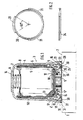
- FIG. 1 shows the desiccant box fully assembled and FIG. 2 shows the bayonet ring in a side view and a top view.
- An air dryer 1 (not shown in more detail) has a screw-on surface 2 for a desiccant box 3. This essentially consists of a hat-shaped housing 4 and a cover 5 inserted into the housing from below.
- the housing 4 has a footprint 14 at the top, the meaning of which will be explained later.
- a hollow cylindrical filter 6 carried by a cartridge 50, which is covered by a bracket 7 and a perforated plate 8 and held down by a spring 9.
- a perforated plate 10 then a filter disk 11 and then another perforated plate 12 are inserted into the cartridge 50, and then desiccant granulate 13 is filled in, which is covered upwards by the perforated plate 8 and braced by the spring 9.
- a ring filter 15 is located under a shoulder of the support cylinder 5.
- the cover 5 inserted into the housing 4 from below has a central line connection with an internal thread 5 ⁇ is provided. In addition, it has several openings 5 ⁇ arranged in a circle, which also serve for the passage of air.
- the lid 5 lies with its inner surface on the ring filter 15 and on the shoulder of the cartridge 50.
- the lid 5 has an inner circumferential surface 16 with which it rests on an inner surface 17 of a hat edge 18 of the housing 4 and can be pushed in as far as possible against a shoulder 4 ⁇ .
- an anti-rotation device 19 which consists of one or more interlocking longitudinal surfaces or webs or grooves.
- a bayonet ring 20 is arranged between the hat edge 18 and the lid 5, the inner diameter of which forms a closed ring is smaller than the outer diameter of the lid 5.
- the bayonet ring 20 has - as can best be seen in FIG. 2 - about three on its outer diameter 60 ° wide bayonet fields 21, and the hat rim 18 is provided on the inside with an annular recess 22 which has three corresponding projecting ramps 23 which can be engaged by the three bayonet fields 21 of the ring 20 when twisted.
- An axial distance between the inner end of the recess 22 and the axially opposite inner plane surface of the ramps 23 is smaller than a stop lug 24 of the bayonet ring.
- annular recess 27 is formed, into which an annular seal 28 with an annular extension 29 is inserted.
- the ring seal 28 covers the lower gap between the cover 5 and the housing with an annular radial part 30 4 and has a clamping lip 31 on the outside, with which it is let into an outer annular groove 32 in the housing 4.
- the desiccant box 3 is screwed onto a threaded connector of the air dryer 1 by means of its thread 5 ⁇ in the cover 5.
- the ring seal 28 establishes the tightness of the connection of the two housings 1 and 4. During this assembly, the cover 5 cannot rotate with respect to the housing 4 because the anti-rotation device 19 between the housing 4 and the cover 5 is effective.
- the air When compressed air flows through the desiccant box 3, the air either flows through the central line connection into the box 3 and after flowing through the entire box 3 through the openings 5 ⁇ (regeneration of the granulate 13) or the air flows through the box into reverse direction and exits at the central pipe connection (drying of the humid air).
Landscapes
- Engineering & Computer Science (AREA)
- Transportation (AREA)
- Mechanical Engineering (AREA)
- Drying Of Gases (AREA)
Abstract
Description
- Die Erfindung geht aus von einem Lufttrockner nach der Gattung des Hauptanspruchs. Ein derartiger Lufttrockner ist älter angemeldet durch die deutsche Patentanmeldung P 35 23 406.7.
- Bei diesem Lufttrockner ist eine Trockenmittelbox verwendet, die zwischen ihrem Gehäuse und ihrem Deckel einen Bajonettverschluß aufweist. Da aber der Deckel in einer Zentralöffnung einen Gewindeanschlußstutzen trägt, mittels dessen die Trockenmittelbox am Gehäuse des Lufttrockners festschraubbar ist, kann es beim Lösen dieser Zentralverschraubung vorkommen, daß sich der Bajonettverschluß der Trockenmittelbox ungewollt öffnet.
- Der oben genannte Lufttrockner mit den kennzeichnenden Merkmalen des Hauptanspruchs hat demgegenüber den Vorteil, daß sich das hutförmige Gehäuse der Trockenmittelbox vom Deckel bei der Montage der Box am Lufttrockner nicht unge wollt trennen kann. Desweiteren ist es von Vorteil, daß die Einzelteilmontage der Trockenmittelbox erleichtert und die Verbindung von Gehäuse und Deckel sicherer ist.
- Ein Ausführungsbeispiel der Erfindung ist in der Zeichnung dargestellt und in der nachfolgenden Beschreibung näher erläutert. Es zeigen: Figur 1 die Trockenmittelbox fertig montiert und Figur 2 den Bajonettring in Seitenansicht und Draufsicht.
- Ein nicht näher dargestellter Lufttrockner 1 hat eine Anschraubfläche 2 für eine Trockenmittelbox 3. Diese besteht im Wesentlichen aus einem hutförmigen Gehäuse 4 und einem von unten in das Gehäuse eingesetzten Deckel 5.
- Das Gehäuse 4 hat oben eine Aufstellfläche 14, deren Bedeutung später erläutert wird. Im Gehäuse 4 ist ein hohlzylindrisches, von einer Patrone 50 getragenes Filter 6 angeordnet, das von einem Bügel 7 und einer Lochplatte 8 abgedeckt und von einer Feder 9 niedergehalten wird. In die Patrone 50 sind zunächst eine Lochplatte 10, dann eine Filterscheibe 11 und darauf eine weitere Lochplatte 12 eingelegt und dann ist Trockenmittel-Granulat 13 eingefüllt, das nach oben durch die Lochplatte 8 abgedeckt und durch die Feder 9 verspannt wird. Unter einer Schulter des Tragzylinders 5 liegt noch ein Ringfilter 15.
- Der von unten in das Gehäuse 4 eingesetzte Deckel 5 hat einen zentralen Leitunganschluß, der mit einem Innengewinde 5ʹ versehen ist. Außerdem hat er mehrere im Kreis angeordnete Durchbrüche 5ʺ, die ebenfalls dem Luftdurchgang dienen. Der Deckel 5 liegt mit seiner Innenfläche am Ringfilter 15 und an der Schulter der Patrone 50 an. Der Deckel 5 hat eine innere Mantelfläche 16, mit der er an einer Innenfläche 17 eines Hutrandes 18 des Gehäuses 4 anliegt und bis zum Anschlag an einer Schulter 4ʹ eingeschoben werden kann.
- Zwischen den beiden Flächen 16 und 17 ist eine nicht näher dargestellte Verdrehsicherung 19 vorgesehen, die aus einer oder mehreren ineinandergreifenden Längsflächen bzw. Stegen oder Nuten besteht.
- Außerdem ist zwischen dem Hutrand 18 und dem Deckel 5 ein Bajonettring 20 angeordnet, dessen einen geschlossenen Ring bildender Innendurchmesser kleiner ist als der Außendurchmesser des Deckels 5. Der Bajonettring 20 hat - wie am besten in Figur 2 zu erkennen ist - an seinem Außendurchmesser drei etwa 60° breite Bajonettfelder 21, und der Hutrand 18 ist innen mit einer ringsförmigen Aussparung 22 versehen, die drei entsprechende vorstehende Rampen 23 aufweist, die von den drei Bajonettfeldern 21 des Ringes 20 beim Verdrehen hintergriffen werden können. Ein Axialabstand zwischen dem inneren Ende der Aussparung 22 und der diesem axial gegenüberstehenden inneren Planfläche der Rampen 23 ist kleiner als eine Anschlagnase 24 des Bajonettringes.
- Zwischen einer axial nach außen gerichteten Schulter 25 des Bajonettringes 20 und einem kleinen Axialansatz 26 des Deckels 5 ist eine ringförmige Vertiefung 27 gebildet, in die eine Ringdichtung 28 mit einem Ringansatz 29 eingesetzt ist. Die Ringdichtung 28 deckt mit einem ringförmigen Radialteil 30 den unteren Spalt zwischen Deckel 5 und Gehäuse 4 ab und hat außen eine Spannlippe 31, mit der sie in eine Außenringnut 32 im Gehäsue 4 festhaltend eingelassen ist.
- Die Trockenmittelbox 3 wird mit Hilfe ihres Gewindes 5ʹ im Deckel 5 auf einen Gewindestutzen des Lufttrockners 1 aufgeschraubt. Die Ringdichtung 28 stellt dabei die Dichtheit der Verbindung der beiden Gehäuse 1 und 4 her. Bei dieser Montage kann sich der Deckel 5 gegenüber dem Gehäuse 4 nicht verdrehen, weil die Verdrehsicherung 19 zwischen Gehäuse 4 und Deckel 5 wirksam ist.
- Bei der Durchströmung von Druckluft durch die Trockenmittelbox 3 strömt die Luft entweder durch den zentralen Leitungsanschluß in die Box 3 und nach Durchströmen der gesamten Box 3 aus dieser durch die Durchbrüche 5ʺ wieder aus (Regenerieren des Granulates 13) oder die Luft strömt durch die Box in umgekehrter Richtung und tritt am zentralen Leitungsanschluß wieder aus (Trocknen der feuchten Luft).
- Im Laufe des Betriebes wird nach einiger Zeit das Granulat 13 unbrauchbar. Nun muß nicht die gesamte Trockenmittelbox weggeworfen werden, sondern es wird wie folgt vorgegangen:
- 1. Abschrauben der Box 3 vom Lufttrockner 1,
- 2. Box mit der Öffnung nach oben auf die Aufstellfläche 14 stelle,
- 3. Herausnehmen der Ringdichtung 28,
- 4. Deckel 5 gegen die Kraft der Feder 9 bis zum Anschlag an der Schulter 4ʹ herunterdrücken,
- 5. Bajonettring 20 entgegen dem Uhrzeigersinn um etwa 60° drehen und herausnehmen,
- 6. Filter 15, Patrone 50 mit Filter 6 herausnehmen,
- 7. Bügel 7 zusammendrücken,
- 8. Granulat 13 ausgießen.
- Dies ist die Demontage. Die Montage erfolgt in umgekehrter Reihenfolge, nachdem das alte Granulat durch neues ersetzt worden ist und die Filter 6 und 15 ausgetauscht wurden.
- Es ist zu erkennen, daß diese Arbeitsgänge einfach und leicht zu berwerkstelligen sind.
Claims (4)
Applications Claiming Priority (2)
| Application Number | Priority Date | Filing Date | Title |
|---|---|---|---|
| DE19863606574 DE3606574A1 (de) | 1986-02-28 | 1986-02-28 | Lufttrockner |
| DE3606574 | 1986-02-28 |
Publications (3)
| Publication Number | Publication Date |
|---|---|
| EP0234229A2 true EP0234229A2 (de) | 1987-09-02 |
| EP0234229A3 EP0234229A3 (en) | 1987-12-09 |
| EP0234229B1 EP0234229B1 (de) | 1989-09-13 |
Family
ID=6295200
Family Applications (1)
| Application Number | Title | Priority Date | Filing Date |
|---|---|---|---|
| EP87100492A Expired EP0234229B1 (de) | 1986-02-28 | 1987-01-16 | Lufttrockner |
Country Status (2)
| Country | Link |
|---|---|
| EP (1) | EP0234229B1 (de) |
| DE (2) | DE3606574A1 (de) |
Cited By (8)
| Publication number | Priority date | Publication date | Assignee | Title |
|---|---|---|---|---|
| FR2595054A1 (fr) * | 1986-03-03 | 1987-09-04 | Wabco Westinghouse Fahrzeug | Cartouche deshydratante a visser sur un deshydrateur de gaz, notamment dans une installation a air comprime d'un vehicule automobile |
| WO1997003872A1 (en) * | 1995-07-24 | 1997-02-06 | Alliedsignal Inc. | Air dryer cartridge mounting system |
| WO2001052973A1 (en) * | 2000-01-20 | 2001-07-26 | Bendix Commercial Vehicle Systems Llc | Air dryer cartridge with coalescing filter |
| WO2002009994A1 (en) * | 2000-07-31 | 2002-02-07 | Wabco Automotive Uk Limited | Pressure relief device |
| US6786953B2 (en) * | 2002-07-26 | 2004-09-07 | Bendix Commercial Vehicle Systems Llc | Spin-on desiccant cartridge with integral oil removal filter |
| WO2008017474A1 (de) * | 2006-08-08 | 2008-02-14 | Knorr-Bremse Systeme für Nutzfahrzeuge GmbH | Druckluftversorgungseinrichtung |
| EP2105186A1 (de) * | 2008-03-28 | 2009-09-30 | KNORR-BREMSE Systeme für Nutzfahrzeuge GmbH | Entlüftungsvorrichtung für eine Druckluftaufbereitungsanlage und Verfahren zum Demontieren einer Lufttrocknerpatrone einer Druckluftaufbereitungsanlage |
| WO2011058006A1 (de) * | 2009-11-11 | 2011-05-19 | Knorr-Bremse Systeme für Nutzfahrzeuge GmbH | Luftaufbereitungsanlage |
Family Cites Families (2)
| Publication number | Priority date | Publication date | Assignee | Title |
|---|---|---|---|---|
| DE8224847U1 (de) * | 1982-09-03 | 1983-12-08 | Daimler-Benz Ag, 7000 Stuttgart | Trocknungsvorrichtung fuer lufttrockner |
| DE3523406A1 (de) * | 1985-06-29 | 1987-01-08 | Bosch Gmbh Robert | Lufttrockner fuer druckluftanlagen |
-
1986
- 1986-02-28 DE DE19863606574 patent/DE3606574A1/de not_active Withdrawn
-
1987
- 1987-01-16 EP EP87100492A patent/EP0234229B1/de not_active Expired
- 1987-01-16 DE DE8787100492T patent/DE3760553D1/de not_active Expired
Cited By (18)
| Publication number | Priority date | Publication date | Assignee | Title |
|---|---|---|---|---|
| FR2595054A1 (fr) * | 1986-03-03 | 1987-09-04 | Wabco Westinghouse Fahrzeug | Cartouche deshydratante a visser sur un deshydrateur de gaz, notamment dans une installation a air comprime d'un vehicule automobile |
| WO1997003872A1 (en) * | 1995-07-24 | 1997-02-06 | Alliedsignal Inc. | Air dryer cartridge mounting system |
| WO2001052973A1 (en) * | 2000-01-20 | 2001-07-26 | Bendix Commercial Vehicle Systems Llc | Air dryer cartridge with coalescing filter |
| WO2002009994A1 (en) * | 2000-07-31 | 2002-02-07 | Wabco Automotive Uk Limited | Pressure relief device |
| US7147228B2 (en) | 2000-07-31 | 2006-12-12 | Wabco Automotive Uk Limited | Pressure relief device |
| US6786953B2 (en) * | 2002-07-26 | 2004-09-07 | Bendix Commercial Vehicle Systems Llc | Spin-on desiccant cartridge with integral oil removal filter |
| US6951581B2 (en) * | 2002-07-26 | 2005-10-04 | Bendix Commercial Vehicle Systems Llc | Spin-on desiccant cartridge with integral oil removal filter |
| WO2008017475A1 (de) | 2006-08-08 | 2008-02-14 | Knorr-Bremse Systeme für Nutzfahrzeuge GmbH | Druckluftversorgungseinrichtung |
| WO2008017474A1 (de) * | 2006-08-08 | 2008-02-14 | Knorr-Bremse Systeme für Nutzfahrzeuge GmbH | Druckluftversorgungseinrichtung |
| US7972418B2 (en) | 2006-08-08 | 2011-07-05 | Knorr-Bremse Systeme Fuer Nutzfahrzeuge Gmbh | Compressed air supply device |
| US8021465B2 (en) | 2006-08-08 | 2011-09-20 | Knorr-Bremse Systeme Fuer Nutzfahrzeuge Gmbh | Compressed air supply device |
| CN101500870B (zh) * | 2006-08-08 | 2012-05-09 | 克诺尔商用车制动系统有限公司 | 压缩空气供应设备及用于压缩空气供应设备的阀壳体 |
| CN101500871B (zh) * | 2006-08-08 | 2012-08-08 | 克诺尔商用车制动系统有限公司 | 压缩空气供应设备及其阀壳体和空气干燥筒 |
| EP2105186A1 (de) * | 2008-03-28 | 2009-09-30 | KNORR-BREMSE Systeme für Nutzfahrzeuge GmbH | Entlüftungsvorrichtung für eine Druckluftaufbereitungsanlage und Verfahren zum Demontieren einer Lufttrocknerpatrone einer Druckluftaufbereitungsanlage |
| WO2011058006A1 (de) * | 2009-11-11 | 2011-05-19 | Knorr-Bremse Systeme für Nutzfahrzeuge GmbH | Luftaufbereitungsanlage |
| CN102666230A (zh) * | 2009-11-11 | 2012-09-12 | 克诺尔商用车制动系统有限公司 | 空气处理装置 |
| US8834616B2 (en) | 2009-11-11 | 2014-09-16 | Knorr-Bremse Systeme Fuer Nutzfahrzeuge Gmbh | Air treatment system |
| CN102666230B (zh) * | 2009-11-11 | 2015-11-25 | 克诺尔商用车制动系统有限公司 | 空气处理装置 |
Also Published As
| Publication number | Publication date |
|---|---|
| EP0234229A3 (en) | 1987-12-09 |
| EP0234229B1 (de) | 1989-09-13 |
| DE3760553D1 (en) | 1989-10-19 |
| DE3606574A1 (de) | 1987-09-03 |
Similar Documents
| Publication | Publication Date | Title |
|---|---|---|
| DE69313791T2 (de) | Filtersystem für druckluft | |
| EP2020259B1 (de) | Trockenmittelbox zum Entfeuchten von Luft | |
| DE3409219C2 (de) | ||
| DE8501736U1 (de) | Vorrichtung zum Abscheiden von Öltröpfchen aus Luft | |
| DE4429822A1 (de) | Vorrichtung zum Abscheiden von Ölaerosol aus Luft | |
| DE3232742C2 (de) | Luft-Trocknungsvorrichtung für Druckluftbremsanlagen von Fahrzeugen | |
| DE1457299C3 (de) | Vorrichtung zum Entfernen von Teilchen aus einem verunreinigten gasförmigen Medium | |
| WO2008017352A1 (de) | Druckluftversorgungseinrichtung für ein nutzfahrzeug und lufttrocknerpatrone | |
| EP0210363A1 (de) | Lufttrockner für Druckluftanlagen | |
| DE102010006556B4 (de) | Luftfilter eines Verbrennungsmotors | |
| EP0234229B1 (de) | Lufttrockner | |
| EP3067102B1 (de) | Wasserabscheider und wasserabscheidesystem mit integrierter wasseraustragseinrichtung | |
| EP4146366A1 (de) | Filtervorrichtung | |
| EP4357000B1 (de) | Filtervorrichtung | |
| EP1495934A2 (de) | Lufttrockner | |
| EP4171781B1 (de) | Filtereinrichtung mit einem filterelement | |
| DE102017012015A1 (de) | Filterelement eines Filters für Flüssigkeit, Ablassverschlusselement für eine Ablassöffnung eines Filtergehäuses, Gehäuseteil eines Filtergehäuses und Filter | |
| DE202009001159U1 (de) | Ölabscheider | |
| DE102009006863B4 (de) | Ölabscheider | |
| EP3359282B1 (de) | Trockenmittelpatrone mit verbesserter trocknung und regeneration | |
| DE102015122169A1 (de) | Lufttrocknerpatrone | |
| EP3532187A1 (de) | Lufttrocknerpatrone | |
| EP0937490B1 (de) | Filtereinrichtung in Modulbauweise | |
| EP4043083A1 (de) | Filtervorrichtung und filterelement | |
| DE102021005289A1 (de) | Filtervorrichtung |
Legal Events
| Date | Code | Title | Description |
|---|---|---|---|
| PUAI | Public reference made under article 153(3) epc to a published international application that has entered the european phase |
Free format text: ORIGINAL CODE: 0009012 |
|
| AK | Designated contracting states |
Kind code of ref document: A2 Designated state(s): DE FR GB NL SE |
|
| PUAL | Search report despatched |
Free format text: ORIGINAL CODE: 0009013 |
|
| AK | Designated contracting states |
Kind code of ref document: A3 Designated state(s): DE FR GB NL SE |
|
| 17P | Request for examination filed |
Effective date: 19880505 |
|
| 17Q | First examination report despatched |
Effective date: 19890213 |
|
| GRAA | (expected) grant |
Free format text: ORIGINAL CODE: 0009210 |
|
| AK | Designated contracting states |
Kind code of ref document: B1 Designated state(s): DE FR GB NL SE |
|
| ET | Fr: translation filed | ||
| GBT | Gb: translation of ep patent filed (gb section 77(6)(a)/1977) | ||
| REF | Corresponds to: |
Ref document number: 3760553 Country of ref document: DE Date of ref document: 19891019 |
|
| PG25 | Lapsed in a contracting state [announced via postgrant information from national office to epo] |
Ref country code: SE Effective date: 19900117 |
|
| PLBE | No opposition filed within time limit |
Free format text: ORIGINAL CODE: 0009261 |
|
| STAA | Information on the status of an ep patent application or granted ep patent |
Free format text: STATUS: NO OPPOSITION FILED WITHIN TIME LIMIT |
|
| PG25 | Lapsed in a contracting state [announced via postgrant information from national office to epo] |
Ref country code: NL Effective date: 19900801 |
|
| 26N | No opposition filed | ||
| NLV4 | Nl: lapsed or anulled due to non-payment of the annual fee | ||
| PG25 | Lapsed in a contracting state [announced via postgrant information from national office to epo] |
Ref country code: FR Effective date: 19900928 |
|
| PG25 | Lapsed in a contracting state [announced via postgrant information from national office to epo] |
Ref country code: DE Effective date: 19901002 |
|
| REG | Reference to a national code |
Ref country code: FR Ref legal event code: ST |
|
| REG | Reference to a national code |
Ref country code: GB Ref legal event code: 746 |
|
| PGFP | Annual fee paid to national office [announced via postgrant information from national office to epo] |
Ref country code: GB Payment date: 19920107 Year of fee payment: 6 |
|
| PG25 | Lapsed in a contracting state [announced via postgrant information from national office to epo] |
Ref country code: GB Effective date: 19930116 |
|
| GBPC | Gb: european patent ceased through non-payment of renewal fee |
Effective date: 19930116 |
|
| EUG | Se: european patent has lapsed |
Ref document number: 87100492.5 Effective date: 19901107 |